*e-mail: [email protected]
Microstructure Evolution of Electron Beam Physical Vapour Deposited
Ni-23.5Cr-2.66Co-1.44Al Superalloy Sheet During Annealing at 600 °C
Li Mingweia*, Zeng Gangb, Zhong Yeshengc, He Feic, He Xiaodongc
aNational Key Lab for Precision Heat Processing of Metal, Harbin Institute of Technology,
Harbin, 150001, China
bHarbin Institute of Technology, School of Material Science and Engineering, Harbin, 150001, China cNational Key Laboratory of Science and Technology on Advanced Composites in Special Environments,
Harbin Institute of Technology, Harbin, 150001, China
Received: April 18, 2012; Revised: July 29, 2012
Microstructure evolution of electron beam physical vapour deposited (EB-PVD) Ni-23.5Cr-2.66Co-1.44Al superalloy sheet during annealing at 600 °C was investigated. The results showed that the as-deposited alloy was composed of only γ phase. After annealing at 600 °C, the locations of diffraction peaks were still the same. The (220) diffraction peak of the deposition side increased with annealing time. The sheet on deposited side had a tendency toward forming (220) texture during post-annealing. No obvious texture was observed at as-deposited and annealed sheet at 600 °C in substrate side. The count and size of “voids” decreased with time. The size of grains increased obviously with annealing time. The ultimate tensile strength of EB-PVD Ni-23.5Cr-2.66Co-1.44Al alloy sheet increased from 641 MPa to 829 MPa after annealing at 600 °C for 30 hours.
Keywords: Physical Vapour Deposited (EB-PVD), Ni-based superalloy, annealing, microstructure
1. Introduction
Ni-based superalloys are one kind of the most promising materials developed for the high-temperature applications and are actually extensively used in aerospace industry for its excellent elevated temperature properties1. Ni-based
superalloy sheets are able to be used for producing metallic thermal protection systems for Reusable Launch Vehicles2-5.
Since the profile of the thermal protection system is a hyperboloid, the sheets prepared with traditional techniques in China couldn’t meet its modeling and size demands. The large-scale microcrystal Ni-based superalloy sheets have been developed in our group. The Electron Beam Physical Vapour Deposition (EB-PVD) process offers many desirable characteristics such as relatively high deposition rates, dense coatings, controllable composition, and low contamination6. The microcrystal superalloy
sheets canbe fabricated by electron-beam physical vapor deposition (EB PVD) method because the technique can provide deposition rate up to 100 nm/s[8]. And the materials
produced by EB PVD technique are dense with controlled compositions and microstructures7,8. Since the size of grains
is smaller, grain growth can occur during either deposition of the film or subsequent heat treatment9. In this paper, the
microstructure evolution of electron beam physical vapour deposited (EB-PVD) Ni-23.5Cr-2.66Co-1.44Al superalloy sheet during annealing at 600 °C was investigated.
2. Experimental
Large-scale Ni-based superalloy sheet (diameter 1000 mm × 0.3 mm) was fabricated by electron-beam physical vapor deposition (EB-PVD) in 6 × 10⁻³ Pa with
a deposition rate of about 2 µm/min on the separable stainless steel substrate at 740 ± 20 °C with rotation speed of 6 rpm. Before deposited of nickel-based alloy, a CaF2 layer with about 5-10 µm thickness was deposited on the substrate surface for removing easily the alloy sheet from the separable substrate. In the following discussion, substrate-side and deposited-side of the produced sheet refer to. The nominal chemical composition of the as-deposited alloy sheet was Ni-23.5Cr-2.66Co-1.44Al (wt. (%)). The samples were annealed in a furnace in 6 × 10⁻³ Pa at 600 °C.
Microstructures of as-deposited and annealed specimens were examined by scanning electron microscopy (SEM), X-ray diffraction (XRD), and transmission electron microscopy (TEM). SEM specimens were etched in the ratio 1:1:1 mixture of HNO3, HCl and HF. TEM specimens were prepared by twin-jet electro-polishing using a solution of 10 vol, (%) HClO4 and 90 vol, (%) CH3COOH around –20 °C at 20 V.
Tensile tests were conducted at room temperature on as-deposited and annealed specimens. The specimens were stained at a rate of approximately 0.02 s−1 with an
3. Results
3.1.
XRD
Figure 1 showed the diffraction patterns of the alloy sheet on the deposited side in the as-deposited and annealing treated at 600 °C for 4, 16 and 30 hours. The results indicated that the as-deposited alloy and annealed alloy were composed of γ phase. The XRD peak height ratios I(111)/I(220) of as-deposited and annealed at 600 °C for 4 and 30 hours sheet on the deposited side, which were calculated from Figure 1, are 3.125, 1.471, and 1.02, respectively. Compared with 6.20 which was the XRD peak height ratios I (111)/I (220) calculated from nickel (JCPDS 65-380), it was possible that the as-deposited sheet showed (220) texture. Variation in the intensities of some reflections suggested changes in the texture with annealing time. Therefore, we could preliminarily infer that the superalloy sheet on deposited side had a tendency of forming a (220) texture during post-annealing. To further evaluate the preferred-orientation of the sheet, XRD rocking curves were measured for the reflections (220). During the rocking curve measurement, the 2θ was fixed at the peak position of (220)
diffraction (around 76.4°), and the incidence angle of X-ray was continuously changed from 0 to 2θ. From Figure 1b, the peak position was close to the half of the peak position of (220) diffraction, which confirms the orientations of (220). The rocking curves can be fitted by Gaussian function, and the Gaussian widths for the sheets at as-deposited and annealing treated at 600 °C for 4 and 30 hours were 49.9°, 36.3° and 28.6°, respectively. Therefore, it was clear that the full width at half maximum (FWHM) of (220) diffraction of
ω-scan rocking curve peaks decreased with the annealing time increasing, which suggested that the (220)-oriented degrees became higher during post-annealing.
Figure 2 showed the XRD patterns of the alloy sheet on the substrate side in as-deposited and annealing treated at 600 °C for 4, 16 and 30 hours. The result indicated that the as-deposited alloy and annealed sheet were composed of
γ phase, too. The XRD peak height ratios I(111)/I(220) on the substrate side were 5.88, 4.54 and 5 for as-deposited and annealed sheet at 600 °C for 4 and 30 hours from Figure 2. The results showed that no obvious texture was existed from the XRD pattern at as-deposited and annealed at 600 °C.
3.2.
Microstructure
Figure 3 showed the cross-section SEM micrographs of as-deposited sheet and annealed at 600 °C for 4 hours, 16 hours and 30 hours. There were some columnar grain structures in sheets of as-deposited and annealed at 600 °C for 4 hours. But it was found that equiaxed grains without columnar grain structure in sheets of annealed at 600 °C for 16 hours and 30 hours.
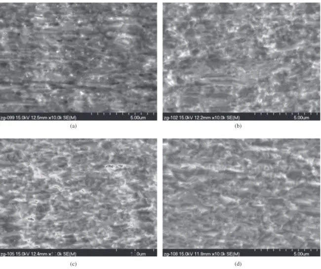
Figure 4 showed the plane SEM micrographs of sheet at as-deposited and annealed at 600 °C for 4, 16 and 30 hours. The small size grains about 0.5 µm were observed in as-deposited sheet. Many voids could be found because some grains fell out owing to etching. At the same time, the amount of voids decreased rapidly. Up to 16 hours, the grain boundaries were unclear and only little voids existed. With annealed for 30 hours, there was free void.
Figure 5 showed the TEM micrographs of as-deposited and annealed sheet at 600 °C for 30 hours. There were no voids in as-deposited alloy with the average size of grains about
Figure 2. XRD patterns of the alloy sheet on the substrate side in as-deposited and annealed.
0.5 µm. An amount of extinction fringes could be observed. After annealed for 30 hours, the average size of grains exhibited a smaller growth in comparison with that of the as-deposited one. But no dislocation existed in the as-deposited sheet and in sheets annealed at 600 °C for 30 hours.
3.3.
Tensile properties
Tensile tests were performed at room temperature on as-deposited and annealed at 600 °C for 30 hours alloys. The stress-strain graph and fracture investigations are shown in Figures 6 and 7, respectively. The ultimate tensile strength of as-deposited alloy sheet was 641 MPa. As promoted by annealed at 600 °C for 30 hours, the values reached 829 MPa, which suggested that post-heat treatment had abilities to improve the mechanical properties of this kind of sheets, and had ability to meet the requirements of metallic thermal protection system. The stress-strain curves of as-deposited sheet (Figure 6) showed that very little plastic deformation occurred before the point at which the stress was sufficient to induce failure. The fracture surface images showed that the as-deposited alloy sheet ruptured along the grain boundaries in brittle fracture mode because of the poor strength between grain boundaries while the
annealed sheet failed in brittle and ductile mixed rupture mode from Figure 7.
4. Discussion
Usually, films are formed through the nucleation of isolated crystals on a substrate surface in initial stage. And substrate is covered with isolated, stable islands of the deposited material. Then these islands begin to form large ones. Finally, a continuous film forms9. In this work, Ni-based
alloy was deposited on CaF2 layer surface. No obvious texture was observed in substrate side of sheet which was attributed to initially random three-dimensional nuclei. For this system, metallic atoms deposited in CaF2 substrate, the deposit atoms were more strongly bound to each other than they were to the substrate. So, small nuclei were formed and are statistically distributed over the substrate surface. The results indicate that small clusters were nucleated directly on the substrate surface. The clusters subsequently grow into islands, which in turn coalesce to form a continuous film. Then, the thickness of film increased with the differently relative growth rates of various faces, promoting the fastest growing face at large supersaturation and allowing the slowest growing face to determine the growth shape of the grain10,11.
Figure 4. The plane SEM micrographs of as-deposited sheet (a) and annealed at 600 °C for 4 hours (b), 16 hours (c) and 30 hours (d).
Figure 6. Stress-strain curves of sheet at as-deposited (a) and annealed at 600 °C for 30 hours (b).
Figure 7. Fracture patterns of tensions of sheet at as-deposited (a) and annealed sheet at 600 °C for 30 hours (b).
During post-process heating, grain growth occurs through motion of grain boundaries. So, the increase in the grain average size of the remaining grains was observed. The grain growth was able to continue owing to little columnar grain structure.
The annealing-induced grain growth promoted the development or enhancement of pre-existing (220) texture from Figure 1. The (110) and other low yield stress grains could dominate during grain growth in highly strained films, if part of the strain has been plastically accommodated12.
The yield stress of a grain in a film also depended on its crystallographic orientation. Simple models for the flow stress of a grain in a polycrystalline film suggested that, for equal-sized grains with (111), (100) and (110) texture, the (110) textured grains have the lowest yield stress, and (111) textured grains had the highest12. From Figure 5a, a mount
of extinction fringes in the grain interior were observed for as-deposited sheet which means that the stresses would be released during annealing process. Therefore, (110) textured grains instead of (100) grains can be favored by strain energy minimization. As a result, the (220) diffraction peak of the deposition side increased significantly.
Grain size and interfacial characteristics (e.g. defects) should be important as far as the properties of microcrystal materials were considered. There was a large amount of interface in EB-PVD micro-crystals sheet. During the present annealing, the amount of the defects such as mono-vacancy-sized free volumes and micro-voids, which obviously influenced the deformation strength and fracture toughness, decreased with annealing time. As a result, the strength and fracture toughness increased during annealing at 600 °C.
5. Conclusion
obvious texture existence was observed from the XRD pattern at as-deposited and annealed at 600 °C at substrate side for sheet. After annealing at 600 °C for 30 hours, no voids could be found on surface. And the ultimate tensile strength alloy sheet increased from 641 MPa to 829 MPa, which suggested that post-heat treatment had abilities to improve the mechanical properties of this kind of sheets.
Acknowledgements
This work was financially supported by the project of NSFC (11172082) and Key Laboratory Opening Funding of Key Laboratory of Science and Technology on Advanced Composites in Special Environments (HIT.KLOF. 2009033, HIT.KLOF. 2009040)
References
1. Brooks CR. Heat treatment, structure and properties of nonferrous alloys. New York: ASM; 1984. p. 139.
2. B l o s s e r M L , C h e n R R , S c h m i d t I H , D o r s ey J T, Poteet CC, Bird RK et al. Development of Advanced Metallic-Thermal-Protection System Prototype Hardware. Journal of Spacecraft and Rockets. 2004; 41:183-194. http:// dx.doi.org/10.2514/1.9179
3. Poteet CC, Abu-Khajeel H and Hsu SY. Preliminary Thermal-Mechanical Sizing of a Metallic Thermal Protection System. Journal of Spacecraft and Rockets. 2004; 41:173-182. http://dx.doi.org/10.2514/1.9174
4. Chen RR, and Blosser ML. Metallic Thermal-Protection-System Pa n e l F l u t t e r S t u d y. Jo u r n a l o f S p a c e c ra f t a n d Rockets. 2004; 41:207-212.
5. Z h u H D , S a n k a r B V, H a f t k a RT a n d B l o s s e r M . AIAA 2005-2181. In: Proceedings of the 46th AIAA/ASME/ ASCE/AHS/ASC Structures, Structural Dynamics & Materials Confer; 2005, Austin, Texas. Austin; 2005.
6. Singh J and Wolfe DE. Review Nano and macro-structured component fabrication by electron beam-physical vapor deposition (EB-PVD). Journal of Materials Science. 2005; 40:1-26 http://dx.doi.org/10.1007/ s10853-005-5682-5
7. Ustinov A, Olikhovska L,Melnichenko T and Shyshkin A. Effect of overall composition on thermally induced solid-state transformations in thick EB PVD Al/Ni multilayers. Surface and Coatings Technology. 2008; 202:3832-3838. http://dx.doi. org/10.1016/j.surfcoat.2008.01.024
8. He XD, Xin Y, Li MW and Sun Y. Microstructure and mechanical properties of ODS Ni-based superalloy foil produced by EB-PVD. Journal of Alloys and Compounds. 2009; 467:347-350. http://dx.doi.org/10.1016/j. jallcom.2007.11.122
9. Thompson CV. On the grain size and coalescence stress resulting from nucleation and growth processes during formation of polycrystalline thin films. Journal of Materials Research. 1999; 14:3164. http://dx.doi.org/10.1557/ JMR.1999.0424
10. Terry SG. Evolution of Microstructure during the growth of thermal barrier coatings by electron-beam physical vapor deposition. [Thesis]. Santa Barbara: University of California; 2001.
11. Sree Harsha KS. Principles of Physical Vapor Deposition of Thin Films. London: Elsevier; 2008.