317
Abstract
The objective of this research is to assess how much the improvement in the com-bustion reaction eficiency can reduce fuel consumption, maintaining the same thermal energy rate provided by the reaction in a pelletizing furnace.
The furnace for pelletizing iron ore is a complex thermal machine, in terms of energy balance. It contains recirculation fan gases and constant variations in the pro-cess, and the variation of a single process variable can inluence numerous changes in operating conditions.
This study demonstrated how the main variables related to combustion in the burning zone inluence fuel consumption (natural gas) from the furnace of the Usina de Pelotização de Fábrica (owned by VALE S/A), without changing process conditions that affect production quality.
Variables were analyzed regarding the velocity and pressure of the fuel in the burners, the temperature of the combustion air and reactant gases, the conversion rate and the stoichiometric air/fuel ratio of the reaction. For the analysis, actual data of the furnace in operation was used, and for the simulation of chemical reactions, the soft-ware Gaseq® was used.
The study showed that the adjustment of combustion reaction stoichiometry pro-vides a reduction of 9.25% in fuel consumption, representing a savings of US$ 2.6 mil-lion per year for the company.
keywords: natural gas, cost reduction, lame, stoichiometry, iron ore, Gaseq®. Rafael Simões Vieira de Moura
Mestrando
Universidade Federal de São João Del Rei - UFSJ Departamento de Ciências Térmicas e dos Fluidos (DCTEF) Programa de Pós-Graduação em Engenharia de Energia (PPGEE – UFSJ)
São João Del Rei – Minas Gerais – Brasil [email protected]
Maysa Teixeira Resende
Mestrando
Universidade Federal de São João Del Rei - UFSJ Departamento de Ciências Térmicas e dos Fluidos (DCTEF) Programa de Pós-Graduação em Engenharia de Energia (PPGEE – UFSJ)
São João Del Rei – Minas Gerais – Brasil [email protected]
José Antônio da Silva
Professor Associado
Universidade Federal de São João Del Rei - UFSJ Departamento de Ciências Térmicas e dos Fluidos (DCTEF) Programa de Pós-Graduação em Engenharia de Energia (PPGEE – UFSJ)
São João Del Rei – Minas Gerais - Brasil [email protected]
Julio Cesar Costa Campos
Professor Adjunto
Universidade Federal de Viçosa - UFV
Departamento de Engenharia de Produção e Mecânica Professor no Programa de Pós-Graduação em Engenharia de Energia (PPGEE – UFSJ) Viçosa – Minas Gerais - Brasil [email protected]
Analysis of combustion
efficiency in a pelletizing furnace
Mechanic and Energy
Mecânica e Energia
http://dx.doi.org/10.1590/0370-44672015690191
1. Introduction
Pelletizing is the process of com-pression molding of a material in the form of pellets. A wide variety of different materials can pass through such a process, including chemical compounds, iron ore, animal feed, among others.
In the case of iron ore, pelletizing in ultraine particles occurs through heat treatment. This ultra-ine fraction (less than 0.15 mm) is found this way in nature or created in the beneicia-tion process. The pelletizing produces spherical agglomerates of sizes in the
8 to 18 mm range, with appropriate characteristics to feed reduction units, such as blast furnaces.
The plant under study has an an-nual budget of production in the range of 4 million tons of iron ore pellets.
Iron ore pellets, derived from the steps of milling, iltering, mixing and pelletizing while still raw and damp, are thermally processed in mobile grill furnaces (Straight Grate). The induration process of iron ore pel-lets, fundamental to obtain adequate mechanical strength of the pellets,
occurs in the burning zone region in the furnace, and is the process step in which all properties of agglomerates are obtained.
In the cooling chamber, the air, at atmospheric temperature, exchanges heat with the hot pellets coming from the burning zone.
Figure 1
Cross-section of
Burning Zone (Matos, 2007).
The burning zone, shown in Figure 1, has the burners where fuel combustion occurs, generating natural gas. The com-bustion gases are mixed with hot gases that come through the recovery duct from the cooling chamber. This mixture of hot gases permeates the bed of raw pellets brought by grid cars, transferring heat to them. The gases are drawn by a cen-trifugal fan after passing through the wind boxes, which retains any solid larger mass material, by gravity. Altogether, there are
37 wind boxes in the furnace, connected to the ducts of the fans, that circulating the gases in the furnace. The burning zone is comprised of 12 wind boxes (numbered 12 and 23).
In his work about the global energy balance in the furnace of Usina 1, from CVRD, in Tubarão, Souza and Machado (1975) proposed a thermal eficiency of about 29.18% for the furnace. The authors emphasize that the energy loss in the burn-ing zone is about 43% of total heat lost
from the furnace.
The annual estimated cost for fuel (natural gas) that feeds the furnace of the plant under study is US$ 28 million, and is the largest portion of the total production costs, corresponding to 35%.
This study suggests the analysis of the combustion mechanism in the burning zone, more precisely scrutinizing the en-ergy imparted by the combustion reaction, and how this energy can be rationalized to obtain lower fuel consumption.
2. Materials and methods
This research included the following variables that affect the energy consumed or given by combustion reaction: the speed and pressure of the fuel in the burner, the temperature of the combustion air and re-agent gases, the stoichiometric conversion rate and the air/fuel reaction. As some data is not possible to collect with the furnace in
operation, some of these variables were ana-lyzed qualitatively, and proposals have been made for their changes, aimed at reducing fuel consumption.
The operational and constructive data of the iron ore pelletizing furnace used in this study were provided entirely by VALE S/A.
To simulate the combustion reac-tions, the Gaseq® software was used. It is a software for chemical equilibrium cal-culation in combustion reactions, which can be obtained for free. The software has a simple and objective platform, with pre-deined situations of chemical balance and a selection of elements and substances
Symbols [ρ] Specific mass (Kg/m³)
[µ] Dynamic viscosity (N.s/m²)
[P1] Inlet pressure (Pa)
[P2] Output pressure (Pa)
[ΔP] Pressure differential (Pa)
[V] Volume (m³)
[Z] Compressibility factor (dimensionless)
[Rg] Molar gas constant (kJ/kmol.K)
[T] Temperature (K)
[A] Area (m²)
[V] Volumetric flow (m³/s)
[v1] Inlet velocity (m/s)
[v2] Output velocity (m/s)
[g] Gravity acceleration (m/s²)
[Ma] Mach number (dimensionless)
[Re] Reynolds coefficient (dimensionless)
[D] Diameter (m)
[J] Quantities of motion ratio (dimensionless)
[Qjet] Jet quantity of motion (Kg.m/s)
[Qflow] Flow quantity of motion (Kg.m/s)
[η] Conversion rate (%)
[cpg] Combustion gases specific heat (J/Kg.°C)
[Tg] Combustion gases temperature (°C)
[Tair] Inlet air temperature (°C)
[LHV] Lower heating value (KJ/m³)
[Vr] Reactants volume (m³)
[Vp] Products volume (m³)
[Q] Thermal power (J)
[Qactual] Actual thermal power (J)
[Qη=0.90)] Thermal power of 90% converted fuel (J)
[mf] Fuel mass flow (Kg/s)
[mg] Combustion gases mass flow (Kg/s)
[mf(actual)] Fuel actual mass flow (Kg/s)
319
that can be selected as reactants and products. The program allows the calcula-tion of incomplete combuscalcula-tion reaccalcula-tions, through the entrance of the concentrations of chemical species, and informs all ther-mochemical properties of reactants and products involved in the reaction.
It is important to emphasize that the manipulation of process variables in this work, in order to obtain a lower mass low of fuel, obeyed some important operational
criteria, such as maintaining the heat energy rate (Q), since the thermochemical parame-ters necessary in the process of induration of iron ore pellets should remain unchanged, in order to maintain the quality of production.
Also in relation to the heat energy rate, models in CFD (Computational Fluid Dy-namics) as shown in the study by Athayde
et al. (2012), demonstrate that it is possible to rationalize the heat transfer between convective low of combustion gases and
the bed of raw pellets in order to maximize power transfer.
Due to the constructive character-istics of the furnace fuel supply system, only the studied fuel in operation was considered; it is natural gas. Therefore, it proved impractical, considering the LHV
(Lower Heating Value) from other fuels, which would also lead to variations in the speciic heat and temperature of the combustion gases.
3. Results and discussion
3.1 Fuel speed influence
The fuel required for the combustion reaction in the furnace is injected into the combustion chamber by 38 burners.
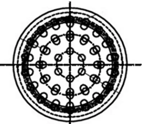
Figure 2 Front view of the outlet nozzle of a burner (provided by Vale S/A).
The body of the burner has 1.067 mm of longitudinal length and 50 mm of diameter, with 10 mm thick walls, and has a nozzle formed by 30 or 36 smaller tubes, with 3 mm of diameter and 10 mm length each, distributed according to Figure 2.
There is a distribution line of natural gas to the burner, which operates at a pres-sure of 200 kPa.
Through the natural gas
composi-tion provided by the supplier of the fuel dealership, and using Gaseq®, it was possible to calculate the density (ρ1), the
dynamic viscosity of the fuel (μ) and the compressibility coeficient (Z), resulting from the species that make up the fuel. Knowing the inlet pressure (P1) in the burners and the combustion chamber pressure (P2) where fuel is injected, we obtain the pressure difference (ΔP), which
comprises the actual pressure drop in the burner, according to the roughness of the building material, turbulence, among oth-ers. We considered a Newtonian luid, in a compressible low, with a compressibility factor (Z) provided by Gaseq® for adjust-ment of state equations. The inluence of temperature upon density was obtained by Equation 1, whereby the density at the output (ρ2) was found by Gaseq
®.
PV = ZR
gT
Through transport of fuel in the burner area (A) and the low rate reading (V) provided by the sensor installed in
the furnace gas delivery line, the initial speed (v1) is deined. With this data, was calculated the output speed (v2), of fuel in
the burner, equal to 332.12 m/s through Equation 2, disregarding the terms involv-ing potential energy.
This calculation is aimed at ob-taining a reference speed in order to determine the type of low and its inlu-ence on combustion. The continuum hypothesis and mass conservation were considered, as well as a low forced into a duct of constant section without ac-cumulation or mass generation in the fuel injection system.
The Mach number (Ma) relates the speed of a body or stream with the speed
of sound in the environment in which it lies. Through the natural gas species composition, its temperature and pres-sure in the burner, the speed of sound in the low was obtained, provided by
Gaseq®. The calculated result for the low of natural gas was in the order of
Ma = 0.77. For 0.2 < Ma < 0.8 values, the luid travels at subsonic speed within the burner showing that there is no tem-perature elevation or pressure arising
from shock waves (which occur when
Ma > 1), which might cause spontane-ous ignition in the fuel. The furnace fuel supply system has pneumatic valves that control the low of fuel in burners, ac-cording to the process needs. In the above calculation, these valves were considered fully open, in which the fuel reaches a higher volumetric low.
In relation to the fuel exit veloc-ity burners, Khalil et al. (2010), in an
(1)
(2)
dm
dt
= 0 =
∂
∂
t
d
ν +
ρ
V dA
experiment on the temperature distri-bution in the lame of methane, a major
constituent of natural gas, shows that for a pressure of 200 kPa, a higher fuel speed
provides better energy distribution of the combustion lame (Figure 3).
Figure 3
Flame Temperature Distribution, (P = 2 (bar) at
Different Velocities). (Khalil et al. 2010).
It is noted that the speed of the analyzed gas on the burner favors a more homogeneous temperature distribution
in the lame.
The Gaseq® software reports the values of the dynamic viscosity of the
fuel luid (μ) and, along with the value of the output speed (v2), we calculated the Reynolds number (Re) of the low.
The Reynolds number (Re) of the fuel low in the analyzed burner nozzle is on the order of 106, shown by Equation 3, which
features a turbulent low (Re> 4000).
In turbulent low conditions in the fuel, which has a different propagation velocity of
the lame, a distorted (wrinkled) lame front laminar appears according to the complexity of the velocity ield proile as shown in Figure 4.
Figure 4
Sketch of differences in local
direction (upper) and flame front topo-graphy (lower) between a laminar and
turbulent flame (Chatrathi et al., 2001).
Locally, the mixture was further spread with the laminar burning velocity, so the fuel consumption increases propor-tionally to the surface area increase. The result is equivalent to a faster and more tur-bulent burning velocity, whose magnitude is related to the intensity of local turbulence and other parameters. The consequence is that the rate of product formation is higher due to the decreased density resulting from the reaction. (Grifiths and Barnard, 1995).
A turbulent lame causes an increase
in fuel consumption in the reaction. This effect can be minimized by changing the geometry of the burner, since it becomes impracticable to change the fuel pressure in the supply network, due to the fuel sup-ply project.
In a study on the effects of fuel speeds and lames on burners, Chatrathi
et al. (2001), demonstrated that for the relationship between length and tube di-ameters (L/D) ranging between 1 and 50, the speed is not affected by the diameter,
and for ratios exceeding 50, the speed tends to increase proportionally to the diameter. In the case under study, for the burner
(L/D = 1067/40 = 26.675).
Using a simple bench test, it is pos-sible to rationalize the consumption of fuel through changes in the ratio length/ diameter of the burner in study, testing prototypes complying to L/D <50 and mea-suring the mass low of fuel by correlating data collected by seeking an optimal point of operation.
(3)
321
3.2 Fuel pressure influence
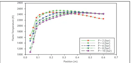
The pressure in the burners study is on the order of 200 kPa in the furnace supply lines. Khalil et al. (2010) in a study
on the influence of pressure variation in lame temperature, illustrates that at different pressures, at the same velocity
of fuel, the temperature variation in the lame does not vary in large proportions, as shown in Figure 5.
Figure 5 Flame Temperature Distribution, (Velocity = 10 (m/s), at Different Pressures) (by Khalil, 2010).
The air that enters on the combus-tion chamber comes from the cooling zone. The load employed in this airlow by the fans causes a cross between the
fuel gas stream arising from the burn-ers and the gas low coming into the combustion chamber.
There is a delection inside the
combustion chamber, as shown in Figure 6, caused by the variation of pressure resulting from a cross between the two lows.
Figure 6 Jet in cross flow (Lefebvre,
1990 cited by Athayde et al., 2012).
Lefebvre (1990) cited by Athayde et al. (2012), patterned delection as a
func-tion of this pressure variafunc-tion, according to Equation 4.
j =
Q
jetQ
flowwhere J is the ratio between the quanti-ties of motion and Qjet and Qflow repre-sent the quantities of motion of the jet and the gas low.
The behavior of the temperature distribution in the lame delection of a burner from a pelletizing plant furnace similar to that studied in
this work is illustrated in Figure 7.
It was modeled by Athayde et al.
(2012) using CFD (Computational Fluid Dynamics).
(4)
Figure 7 Temperature profile along the flame
from a burner into the combustion
In the combustion chamber of the furnace under study, there is a deflection in the flame around an intersection of the lows.
Reducing the air speed from the cooling chamber will surely result in lower fuel consumption by reducing the deflection in the flame caused
by the change in pressure from the cross low, resulting in better lame propagation and consequently better heat transfer.
3.3 Conversion rate influence
The conversion rate (η) of a com-bustion reaction refers to the conversion percentage of reagents in products,tak-ing as reference the complete combustion stoichiometry, in which η = 1.
The composition of natural gas
showed in Table 1 comprises the average of the irst ive months of 2015 of the gas received from the dealership by VALE S/A.
Natural gas composition
Month Methane (%) Ethane (%) Propane (%) Butane + (%) N2 + CO2 (%) N2 (%)
1 88.11 6.56 2.29 0.66 2.37 0.59
2 88.28 6.44 2.28 0.65 2.35 0.58
3 88.06 6.47 2.30 0.76 2.41 0.57
4 88.44 6.20 2.22 0.72 2.41 0.56
5 88.68 6.10 2.19 0.76 2.27 0.59
Average 88.32 6.35 2.26 0.71 2.36 0.58 Table 1
Average of natural gas composition.
In this work, there was a compara-tive study by modeling an equation with a stoichiometric amount of conversion rate
η = 0.90. The reactions were simulated in
Gaseq® and the temperature of the com-bustion gas was collected in the software
for calculating the thermal energy liber-ated. The stoichiometric balance is shown in Equation 5 below.
η=0.90:
[C
1.1064H
4.1656+ 0.0178 CO
2+ 0.0058 N
2] + 2.0925*(O
2+ 3.76 N
2)
→
0.9958 CO
2+ 0.1106 CO +
+ 0.0178 CO
2+ 0.0058 N
2+ 2.0828 H
2O + 3.76*2.0925*N
2The Gaseq® software provided all the properties of the reactants and products, necessary for the development of the study.
With the temperature of the
combustion gases for η = 0.90, and
temperatures measured in the furnace burners, it was possible to deter-mine the rate of energy provided by combustion (Q) in both cases
(theo-retical for η=0.90 and actual), using Equation 6, which relates the energy released by the fuel with the energy for elevating the temperature of the combustion gases.
Q =
.m
.fLHV
-
m
. gcp
g(
T
g- T
air)
The mass low of fuel (mf=1.741
Kg/s), for both cases, were considered as the product of the volumetric low rate of fuel (Vf=2.318 Nm³/s) measured in the furnace under standard operat-ing conditions and the fuel density (ρf)
under standard conditions.
T h e l o w e r h e a t i n g v a l u e
(LHV = 36048 kJ/m³) of natural gas
fuel corresponds to an average of 150 days of the reports provided by the concessionaire, considered the same in both cases. The mass low rate of
combustion gas (mg) corresponds to
the relative ratio of reactant volumes and product volume (Vr /Vp) obtained by Gaseq®, the density of reagents
(ρr) and the fuel consumption rate
(mf). The speciic heat of lue gases
(Cpg) was obtained by Gaseq® for the
species composition in both cases. The variations in the speciic heat of lue gases has a direct inluence on fuel consumption, since all the energy generated in the combustion reaction depends on the composition of the speciic heat of lue gases to be transferred to the bed of raw pel-lets at a rate more or less effective, depending on its value, Turns (2013) presents a polynomial model to obtain the specific heat in mixtures, that
the software Gaseq® simulates with
excellent approximation. The gas outlet temperature (Tg) was obtained by Gaseq® for η = 0.90 and collected in the ield for the real situation. The temperature of the combustion air
(Tair = 859 °C) was measured in the
furnace and is considered the same
for both cases.
For the calculations, the ther-mal power of combustion in current conditions is Qactual=52.018 MJ and Qη=0.90=57.822 MJ, therefore a 11.15% greater heat input by combustion reac-tion adjustment.
Whereas the maintenance of the same rate of power generation, similar to the current required for induration of the pellets, and adjusting the mass low of fuel (mf) for the model in which Qη=0.90, came to a value of mf=1.579 Kg/s for the same furnace operating conditions.
A reduction of 9.25% in fuel consumption. Table 2 compares the results.
(5)
323
Table 2 Comparing between
current situation and η = 0.90
for the thermal gains and fuel consumption.
Keeping the fuel consumption (mc) Keeping the thermal power (Q)
Qactual (MJ) Qη=0.90 (MJ) mf(actual) (Kg/s) mf(η=0.90) (Kg/s)
52.018 57.822 1.741 1.579
Gain of 11.15% in thermal power Reduction of 9.25% in the fuel consumption
The installation of a combustion gas analyzer on the furnace drawing system is indicated (there are models in the industry
that analyze the concentration of species COx, NOx and SOx). Through analysis of the species composition of the combustion
products, it is possible to adjust the supply of fuel to a better conversion rate (η), which can result in 9.25% consumption reduction.
3.4 Air/fuel ratio influence
One of the ways to achieve a high conversion rate is through the air/fuel ratio. The fuel has needed to react with the greatest amount mass, possibly oxy-gen, near the stoichiometric balance of
the reaction, to carry out combustion as nearly as possible to be complete. Variations of 20% surplus air volume in the methane combustion reaction can reduce the ignition temperature of
up to 10%. Table 3 shows the relation-ship between the variation of the air/ fuel ratio and the ignition temperature of methane, the main component of natural gas.
Proportion of theoretical air (%) m³air/m³methane Ignition temperature (°C)
80 10.67 740
100 9.52 705
110 8.00 698
120 6.85 666
Table 3 Methane Ignition Temperature for Various Concentrations of Air/Fuel mix.
(adapted from Gas Engineers Handbook/ SINDE)
A low ignition temperature involves a smaller amount of energy given off to perform the reaction, and consequently better utilization of the energy released by the fuel. Thus, excess air can increase the performance of combustion, since it has been analyzed so that the excess air that hangs in the combustion does not absorb
part of the energy released. Vlassov (2001) admits in his work that an excess of 7% air relative to the volume of fuel in natural gas reactions is ideal, while Bazzo (1995) states that over 12% would be advisable.
Figure 8 relates the amount of air volume, by the area of each wind box in the burning zone of the furnace, available
for combustion reaction with the fuel vol-ume in the same region. Through the fuel low calculations in the burners and the low of air from the down comers in the oven under study, it was possible to proile the ratio of the volume of air available in the chamber and the volume of fuel in each wind box in the region of the burners.
Figure 8 Ratio between the volume of air available, and the volume of fuel into the wind boxes of the combustion region in the furnace.
The result showed that there is ex-cess air volume in relation to fuel volume in the combustion chamber at a different ratio. An analysis of chemical species from combustion gases must be carried out to deine the real rate of oxygen that is being
consumed by the fuel. Dadam (2005), in their work, varying the air / fuel ratio in the combustion of natural gas, achieved savings of 48.9% fuel, only by adjusting the excess air in the reactants.
Through the composition of the
chemical species in the products of com-bustion, it is possible to determine which weight of oxygen was consumed in the combustion reaction, and thus deine the actual air/fuel ratio.
3.5 Combustion air temperature influence
An important property of the lame temperature analysis is the temperature of the air for combustion (Tair). In his work, Dadam (2005) shows that the higher the temperature of the air reacting with the fuel, the higher is the lame temperature,and hence, higher energy is imparted by the reaction. The air temperature in the fur-nace combustion chamber is in the order of Tair = 859°C, which enables a reduction in fuel consumption. However, an analysis of the concentration of the reactants should
be performed, monitoring the temperature in the combustion chamber, because high temperatures of combustion air tend to reduce its speciic weight, which in a closed system, such as the burning zone, can af-fect the air/fuel ratio.
4. Conclusions
The fuel consumption of a heat en-gine, the size of a pellet furnace, is linked to structural, thermal, chemical and luid dynamics factors. The analysis of the com-bustion performance is just the irst step for future studies which should contain
the largest possible number of variables in determining the overall eficiency of the system, mainly the burning area, the larger thermal losses region.
For the adjustment of combustion, the installation of a lue gas analyzer in
the furnace drawing system is essential. It was concluded that the adjustment of a stoichiometric conversion rate η = 0.90 provides a reduction of 9.25% in fuel consumption, representing a savings of US$ 2.6 million per year for the company.
5. Acknowledgments
The authors thank VALE S/A for all the provided information and CAPES for inancial support.
6. References
ATHAYDE, M., NUNES, S.F., SILVA, G.A.L., SOUSA, F.D.A., ARIMA, M.N., In: INTERNA-TIONAL CONGRESS ON THE SCIENCE AND TECHNOLOGY OF IRONMAKING, 6, 2012. Rio de Janeiro: abm, 2012. Novel burner design supported by cfd to minimize deposits inside combustion chambers of samarco pelletizing furnace, p.100-105.
BAZZO, E. Geração de vapor. 2. Ed. Florianópolis: UFSC, 1995. 216 p.
BARATI, M., Dynamic simulation of pellet induration process in straight-grate system. Interna-tional Journal of Mineral Processing, London, v.89, p.30-39, December 2008.
CHATRATHI, K., GOING, J. E., GRANDESTA, B. Flame propagation in industrial scale pi-ping, Process Safety Progress 286-294. 2001.
DADAM, A. P., Análise térmica de um forno túnel utilizada na indústria de cerâmica vermelha.
Florianópolis: Programa de Pós-graduação em Engenharia Mecânica, Universidade Federal de Santa Catarina, 2005. 125 p. (Dissertação de Mestrado em Engenharia Mecânica).
GRIFFITHS, J.F., BARNARD J.A. Flame and Combustion, 3rd Edition. Front Cover. CRC Press, Dec 30, 1995 - Science - 328 p.
KHALIL R.H., SAKHRIEH A., HAMDAN M., ASFAR J. Effect of pressure and inlet velocity on the adiabatic lame.Jordan Journal of Mechanical and Industrial Engineering, v. 4, p.21-28, January 2010.
MAJUMDER, S., NATEKAR, P., RUNKANA, V. Virtual indurator: a tool for simulation of induration of wet iron ore pellets on a moving grate, computers and Chemical Engineering,
33, p. 1141-1152, 2009.
MATOS, A.P. Inluência da temperatura, pressão, produção e granulometria no processo de secagem das pelotas cruas, Ouro Preto: REDEMAT-UFOP, 2007. 150p. (Dissertação de Mes-trado em Engenharia Metalúrgica).
MEYER, K., Pelletizing of Iron Ores. Düsseldorf: Springer-Verlag mbH, 1980. p 205.
MORLEY, C. Developer of software Gaseq®, available in <http://www.gaseq.co.uk/> - Accessed
in 6/25/2015, 21:30:30.
SOUZA, R.P., MACHADO, A.F. Balanço térmico de um forno de pelotização (Lurgi-Dravo) de minério de ferro hematitico, intern report, CVRD, 1975.
TURNS, Stephen R. Introduction to combustion – concepts and applications. (3.ed.). McGraw--Hill education, 2013.
VLASSOV, D. Combustíveis, combustão e câmaras de combustão. Curitiba: UFPR, 2001, 185 p. the setting of this parameter tends to
sig-niicantly reduce fuel consumption in the pelletizing furnace.
It is indicated also for this analysis, the installation of a gas analyzer in the furnace.
Depending on the result of the
concen-tration of products, maneuvers in the valves of the fuel supply system can be made to reduce fuel consumption.