53
Abstract
Metal droplets generated by an impinging jet, play an important role in metal reining processes, mainly in oxygen steelmaking, where the droplets are ejected into the slag phase. Since the available interfacial area of droplets is very high in this pro-cess, the generated droplets enhance the rates of heat transfer and chemical reactions. Therefore, knowledge of the metal droplet generation rate, size distribution and resi-dence time in the slag are of industrial relevance. In this work, the isothermal, tran-sient low of an incompressible air jet impinging onto an air/water interface at room temperature has been simulated to obtain a better understanding of the droplet ejec-tion phenomenon. The interface was tracked throughout time using the volume of luid (VOF) technique. The governing equations formulated for mass and momentum con-servation and the k-ε turbulence model are solved in the axisymmetric computational domain using the commercial code FLUENT. The droplet ejection rates calculated with computational luid dynamics model are compared to experimental data reported in literature, showing partial agreement, being the incompressibility assumption the probable reason for the deviation observed, which was as far pronounced as the great jet velocity. Nevertheless, the model presented shows itself as a relatively good starting point for the construction of more complex ones (with less simplifying assumptions) which should be able to offer a means to increase the understanding of the droplet ejection phenomena.
keywords: Numerical simulation; computational luid dynamics; volume of luid; top blown; droplet ejection.
Hiuller Castro Araújo
Engenheiro Metalurgista pela
Universidade Federal de Ouro Preto – UFOP Escola de Minas
Ouro Preto - Minas Gerais - Brasil [email protected]
Eliana Ferreira Rodrigues
Professora
Universidade Federal de Ouro Preto – UFOP Escola de Minas
Departamento de Engenharia Mecânica Ouro Preto - Minas Gerais - Brasil [email protected]
Elisangela Martins Leal
Professora
Universidade Federal de Ouro Preto – UFOP Escola de Minas
Departamento de Engenharia Mecânica Ouro Preto - Minas Gerais - Brasil [email protected] [email protected]
Numerical analysis
of the liquid ejection due to
the gaseous jet impact through
computational fluid dynamics
Mechanic and Energy
Mecânica e Energia
http://dx.doi.org/10.1590/0370-44672015710079
1. Introduction
The impact of gaseous jets onto gas/liquid interfaces is commonly employed in the metal industry as a way to both stir the liquid phase and introduce chemical species through direct contact between the phases. In the steelmaking industry, the main application of such jets is found in the Linz and Donawitz (LD) oxygen steelmaking process. The oxygen jet is accelerated at supersonic speeds through a convergent-divergent valve and causes the shearing of the metal surface, a phenomenon that is accom-panied by the ejection of metal droplets toward the slag (Deo et al., 1996). The formation of the emulsion is primar-ily responsible for the interfacial area generation required for the reaction
rates needed.
Metal droplets and gas bubbles have a inite residence time in the emul-sion and the countercurrent low of metal droplets and gas bubbles within the emulsion are of relevance to the formation of slag and the kinetics of oxidation/reduction reactions in the converters oxygen (DEO et al., 1996).
According to Geiger et al. (1982), the reaction rates that occur in the emulsion metal/slag depends mainly on three factors: (a) the amount of metal in the emulsion metal/slag; (b) the size distribution of the metal drops ejected and (c) the residence time of the droplets in the slag phase. Among the above listed items, the study of metal amount in the emulsion is divided into
two groups: cold experiments, where nitrogen is blown into water at room temperature and hot experiments, which blows nitrogen on molten metal at 1650ºC (STANDISH and HE, 1989, 1990; IRONS et al., 2003).
2. Interaction between jets and liquids
Molloy (1970) investigated the ways of interaction between a gas jet and the surface of a liquid and noted the occurrence of three different behaviors, depending on the gas speed and the distance between the interface and the spear: (a) depression: a jet of lower speed or with a large distance between the lance tip and the surface of the
liquid promotes the formation of a small surface depression (Figure 1a);. (b) spread-ing: a jet of increased speed or a decrease in the distance of the lance tip and the surface promotes the formation of a shallow depres-sion in which is observed a large amount of luid ejected from the jet (Figure 1b); and (c) penetration: with the continuous increase in
speed or reduction of the distance between lance tip and surface, where there occurs a deep penetration of the jet into the dense phase, with an apparent reduction in the amount of liquid directly scattered by the jet (Figure 1c). Generally, only the last two behaviors are found in pneumatic steelmak-ing processes (Geiger et al., 1982).
Figure 1
Deformation modes of an interface due to the jet impact: (a) depression; (b) spreading and (c) penetration. Legend: (1) valve; (2) jet exit region; (3) jet along the interface; (4) stagnation point of the original jet; (5) jet se-paration point along the interface; (6) two--phase flow (adapted from Molloy, 1970).
3. Computational and numerical modeling
As the speed with which the gas leaves the nozzle is relatively high, it is suitable that the low be simulated using a turbulence model. Turbulent low ields are character-ized by luctuating speeds. This work uses the k-ε turbulence model. The k-ε model is a
semi-empirical model based on a transport equation model for the turbulent kinetic energy (k) and its dissipation rate (ε). The transport equation for k is derived from the exact equation, while the equation for ε was obtained using physical reasoning and its
exact mathematical counterpart (FLUENT, 2006). These models use the hypothesis of a diffusive gradient relate to the Reynolds tensor, the gradients of the average velocity and the turbulent viscosity, as shown in the following ratio (XIMENES, 2004):
k
3
2
ij
t
⎟
⎟
+
ρ
δ
⎠
⎞
⎜
⎜
⎝
⎛
∂
∂
+
∂
∂
μ
−
=
i j j i j ix
u
x
u
u
u
Where: µt is the turbulent viscosity and k is the turbulent kinetic energy. The
turbulent kinetic energy (k) and its dis-sipation rate (ε) are obtained from the
following transport equations (FLU-ENT, 2006):
( )
(
)
k kk t
i
G
S
x
σ
µ
x
u
x
t
⎥
⎥
⎦
+
+
⎤
⎢
⎢
⎣
⎡
∂
∂
⎟⎟
⎠
⎞
⎜⎜
⎝
⎛
+
μ
∂
∂
=
ρ
∂
∂
+
ρ
∂
∂
j i ik
k
k
( )
(
)
εε
+
ε
ρ
−
ε
+
⎥
⎥
⎦
⎤
⎢
⎢
⎣
⎡
∂
ε
∂
⎟⎟
⎠
⎞
⎜⎜
⎝
⎛
+
μ
∂
∂
=
ε
ρ
∂
∂
+
ρε
∂
∂
S
k
C
G
k
C
x
σ
µ
x
u
x
t
1ε k 2εt i 2 j j i
In these equations, Gk represents the turbulent kinetic energy generation due to the speed gradients; C1ε and C2ε
are constants; σk and σε are turbulent
Prandtl numbers for k and ε,
respec-tively; and Sk and Sε are the source terms of k and ε, respectively. The constants of the k-ε turbulence model,
C1ε , C2ε , Cµ, σk and σε have the standard
values of 1.44; 1.92; 0.09; 1.0; and 1.3,
respectively. A complete discussion of the turbulence model k-ε can be seen in Wilcox (1994). The properties of the luids used in the numerical model are shown in Table 1.
Property Liquid water Air Specific mass [kg/m3] 998.20001 1.225
Specific heat [J/kg.K] 4182.00 1006.43 Thermal Conductivity [W/m.K] 0.60 0.0242
Dynamic Viscosity [kg/m.s] 0.0010003 1.7894 × 10⁻⁵
Molecular Mass [kg/kmol] 18.0152 28.966 Characteristic distance of L-J * [10-10 m] 0 3.711
Energy parameter of L-J [K] 0 78.6 Thermal expansion coefficient [1/K] 0 0
Table 1
Values of the properties of
the fluids used in the numerical model.
55
4. Results and discussion
Six computer simulations were car-ried out, where the jet speeds were vacar-ried for the computational domain (uin). The
problem was numerically simulated for speeds ranging from 56.2 to 116.2 m/s, steps of 10 m/s. Thus, it was possible to evaluate the liquid ejection rates cor-responding to Weber numbers ranging between 4.5 and 19.3.
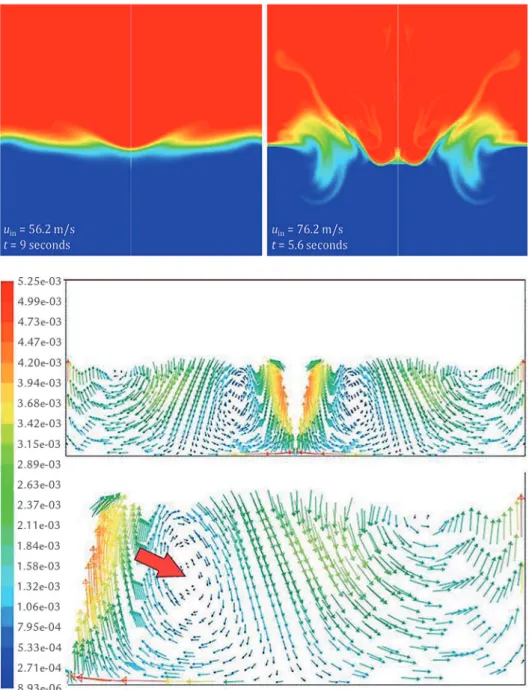
The observation of the interaction modes between gas stream and liquid pool can be made by means of volumetric frac-tion contour plots in order to evaluate the instantaneous distribution of the phases in the computational domain. Figure 2 shows
a contour map obtained for two different input speeds. In this igure, for the lower speed, it is noticed that a diffused region can be identiied on the edge of the cavity produced by the jet, suggesting that there exists a spray of water. The presence of the spray corresponds to the way indicated in Figure 1a, the generation of droplets observed by Standish and He (1989), characteristic of moderate gas low and/ or large heights lance. As for the higher speed, the interaction mode described by Molloy (1970) as penetration mode (Fig-ure 1c) is observed. This result conirms that the increase in jet speed in the
com-putational domain leads to the increase in the interaction between the jet and the bath, and a much larger amount of water suspended on the liquid pool.
In addition to promoting the liquid droplets ejection, the jet impact induces the movement of the liquid. Figure 3 shows the velocity ield of the liquid phase obtained by numerical simulation for an input speed of 66.2 m/s. In this igure, one can observe the formation of vortices in the liquid phase in the anti-clockwise around the axis of symmetry, where the velocity vectors in the liquid phase are expressed in m/s and colored by velocity magnitude.
Figure 2 Volume fraction contour map (phase water in blue) in the computer simulation at different time.
Figure 3 (a) Velocity field in the liquid phase to 66.2 m/s. (b) the right portion showing a vortex in the liquid phase induced by the jet.
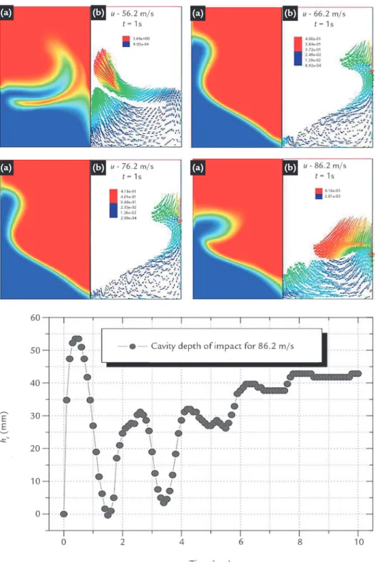
Figure 4 shows the volume fraction map (index a) and the corresponding ve-locity ields (index b) for the time simula-tion of 1 second. The volume fracsimula-tion is
in the left and the velocity ield is in the right. In all simulations, it was observed that the primary impact (the irst moment of blowing), the jet moves radially large
depth of the cavity. In the case of higher jet velocity, a lower spreading liquid is observed. This apparent nonsense can be resolved by the associated velocity ield analysis, which clearly shows that at the time of 1 second, blowing is at a more advanced stage of evolution, since the liquid delected radially towards the
vertical walls of the model is already offset toward the pool.
Figure 5 shows the variation of impact cavity calculated by CFD model over the simulation time with the input speed of 86.2 m/s. Note the great dis-turbance in the early stages, denoted by large amplitude of oscillation followed
by damping and then the tendency of the cavity depth oscillates around an equilib-rium value. These observations conirm the interpretations of Nguyen and Evans (2006) that, in general, the simulation of the impact of the gas jet in a liquid/ gas interface reaches a quasi-steady state within the irst 10 seconds.
Figure 4
Graph represents (a) a volume fraction map to different input velocities and (b) the velocity field in the cells that satisfy the condition 0.6 ≤ φwater ≤ 1.0.
Figure 5
Time variation of the cavity depth generated by the gaseous jet impact.
5. Conclusions
In this work, the results of transient and isothermal (25ºC) numerical simula-tions in two dimensions of the impact of the air jet in the air/water interface were pre-sented. The simulations were compared to
both experimental data of ejection rates and models of the depth of the cavity generated by the impact provided by literature. Sim-plifying assumptions were adopted for the numerical modeling; that is, the gas phase
was considered to be incompressible and the low was considered to be isothermal.
The analysis of contour maps of volumetric fraction showed that the computer model was able to exhibit the
(a) (b) (a) (b)
57
ways of generating droplets comparable to those observed in the physical model-ing usmodel-ing a high speed cinematography technique (Standish and He, 1989). The results led also to observe the change in the intensity of the interaction jet / liquid pool with increasing jet speed in the
com-putational domain.
A comparison of the ejection rates calculated by the model with those re-ported in the literature showed partial agreement, with deviations ranging from about 30 to 50%. This hypothesis should, however, be veriied by conducting a new
set of simulations, taking the energy equa-tion and the compressibility of the gaseous phase into consideration. The predicted depth of the impact cavity proved to be very eficient. This result agrees with those obtained by simulation of the same physi-cal situation (Nguyen and Evans, 2006).
Acknowledgments
References
The authors acknowledge the Brazilian Federal University of Ouro
Preto (UFOP) and those who helped in the execution of this project.
DEO, BRAHMA et al. Characterization of slag metal droplet gas emulsion in oxygen steelmaking converters. ISIJ International, v. 36, n. 6, p. 658–666, 1996.
FLUENT. FLUENT 6.3 User’s Guide. Lebanon, 2006.
GEIGER, GORDON H. et al. BOF steelmaking volume one introduction, theory and design. Warren dale: Iron and Steel Society of the American Institute of Mining,
Metallurgical and Petroleum Engineers, 1982. cap. Paul V. Chapter Five Theory
of B.O.F. Reaction Rates, p. 612.
IRONS, GORDON et al. Generation of droplets in slag metal emulsions through top gas blowing. ISIJ International, v. 43, n. 7, p. 983–989, 2003.
MOLLOY, N. A. Impinging jet low in a two phase system: the basic low pattern.
Journal of the Iron and Steel Institute, v. 208, n. 10, p. 943–950, 1970.
NGUYEN, AHN V. EVANS, GEOFFREY M. Computational luid dynamics mo-deling of gas jets impinging onto liquid pools. Applied Mathematical Modeling,
v. 30, p. 1472–1484, 2006.
STANDISH, NICHOLAS, HE, QING LIN. Drop generation due to an impinging jet and the effect of bottom blowing in the steelmaking vessel. ISIJ International,v. 29, n. 6, p.455–461, 1989.
STANDISH, NICHOLAS, HE, QING LIN. A model study of droplet generation in the b.o.f. steelmaking. ISIJ International, v. 30, n. 4, p. 305–309, 1990.
WILCOX, DAVID C. Turbulence modeling for CFD. (2nd printing-with corrections). La Canada: DCW Industries, 1994. 460 p.
XIMENES, CLEBER SANDIM. Aplicação de técnicas de luidodinâmica
computa-cional (CFD) em fornos para produção de cimento. Campinas: UNICAMP, 2004.