ASSESSMENT OF A TIMBER STRUCTURE
IN THE “ERMIDA DA ASCENSÃO DE CRISTO” IN LISBON
Diana Araújo1* and Dulce Franco Henriques11: Civil Engineering Department
ISEL – Instituto Superior de Engenharia de Lisboa Instituto Politécnico de Lisboa
Rua Conselheiro Emídio Navarro, 1, 1959-007 Lisboa
e-mail: [email protected], [email protected], web: http://www.isel.pt Keywords: Timber structures, assessment, degradation, grading rules, strength classes, critical
section
Abstract This paper presents the assessment of a timber structure in service and the aspects that should be consider for its proper development. To assess wooden structures is necessary to know not only the material and its characteristics but also the degradation agents to what can be subject and the appropriate inspection and diagnosis techniques for each case. The case presented in this work is the last floor structure of the "Ermida da Ascensão de Cristo", situated in Bairro Alto, Lisbon, Portugal. An inspe ction plan to the structure was followed which included several techniques of assessment namely visual inspection, moisture content determination and the use of semi-destructive devices to know the drill resistance and the penetration resistance of the wood. The use of traditional and non-traditional methods allowed the conjugation of information and obtaining results. A survey of the existent normalization was realized which allows the grading of the timber, in both qualitative and quantitative terms: grades and strength classes. The Portuguese standard NP 4305:1995 was followed in the measurement and assessment of only three grading rules: knots, slope of grain and rate of growth. The extension of the damage suffered by the structure due to the attack of wood boring insects was also evaluated, and was determined the loss of section. By the standard EN 338:2009, the characteristic values were determined, which, following the methodology of standard EN 1995:2004, allowed the evaluation of the structure behaviour to bending, deformation and shear.
The use of standard NP 4305:1995 in a simplified way allows its adaptation to a timber structure in service, characterization and assessment in order to be able to determine solutions to its rehabilitation.
1. INTRODUCTION
In Portugal it is common the structural application of timber in buildings especially in the old ones before the twenties and thirties from the XX century. Being the wood a natural material, it presents particular characteristics that will influence directly its behavior, strength and durability. So it is necessary to know the physics and mechanic behavior of this material: due to the ambient water content, due to the different efforts that it can be subject to, or due to the different degradation agents. For this reason, one must have a solid knowledge not only about the material, in a general way, but also about the type of wood that can be found in service, and the specificities that can be found in situ too.
Although there are buildings and structures without problems and operating in full conditions there are many defects that can be find on timber structural elements. The degradation agents usually do not cause extensive or serious damages resulting essentially in aesthetic problems, such the superficial ageing. Concerning the biological agents, they can cause extensive damages and can seriously compromise the resistance and safety of the structure. The most important are the rot fungi and subterranean termites that develop with the increase of the water content in wood above 20%, but also wood boring insects (Hylotrupes bajulus L or Anobium punctatum),. The building rehabilitation can have the goal of the utilization continuity or the attribution of a new function. Even so, in both cases, the major target is its and their users’ safety. For the rehabilitation proceed with the principle of minimum intervention [1], it is necessary a correct structure assessment. As defended by Anthony et al. [2] timber in historic structures can be graded visually in situ to determine appropriate design values, thus reducing the need to replace historic fabric and avoiding costly, and often unnecessary, repair and replacement decisions. Many methodologies can be followed in in situ elements assessment, without the need of destructive tests, using visual assessment, observing the all structure, dimensions, elements, supports and bonds between elements, and more carefully, element by element, taking into account the existent degradation and some intrinsic parameters such knots or fissures. Using some devices and others methodologies, it is possible to have a complement of information, as water content in wood, its surface hardness or its residual section.
All information allows obtain the visual grades of all elements, and in this specific academic work, the assignment of visual grades [3] to strength classes [4,5] by Portuguese and European standards. This way, it becomes possible the structural calculation based on EN 1995:2004, verifying the structure to necessary Ultimate limit states or serviceability limit states required.
2. EN 1912 - STRENGTH CLASSES - ASSIGNMENT OF VISUAL GRADES AND SPECIES: CASE STUDY
This work was carried out in a timber structure in service in a little chapel called Ermida da Ascensão de Cristo situated in Bairro Alto, Lisbon, Portugal. This chapel is located in a special protection zone named “Convento dos Paulistas”, and is located a few meters west of the Santa Catarina’s Church. The “Ermida” was founded in 1500, but suffered semi ruin when an earthquake happened in 1755 that destroyed most part of the capital. It was still rebuilt in the
dimensions, with 7,3 m of façade (Figure 1 b.), being flanked by an old habitational building and a parking silo built in the year of 2000 with reinforced concrete.
a) b) Figure 1.a) Ceiling structure b) Chapel’s facade
The “Ermida” has stone masonry walls plastered with lime mortars. The strength structure of floors, stairs and roof is in hardwood and softwood timber. Has also glazed tiles well conserved, with biblical scenes as well side altars in wood.
The timber structure to assess is the ceiling of a living room in the third floor with most recent construction. This space served to housing until the mid-90s. The structure is all in maritime pine wood (Pinus Pinaster, Ait.).
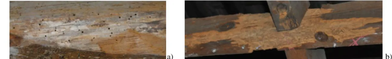
In this structure were visually assessed 28 beams (Figure 1 a.). Biological degradation caused by wood boring insects with larvae commonly known as woodworms of the species of
Hylotrupes bajulus (House longhorn beetle) and Anobium punctatum (Common furniture beetle) was found. The degradation by the last one was signed by the presence of small and numerous holes in the surface of 13 beams (Figure 2 a.). The degradation by Hylotrupes bajulus was observed by the presence of sawdust in large quantities compacted inside the galleries and the big holes with elliptical shape [6], as well high section losses that compromised the structural condition of some beams (Figure 2 b.).
a) b)
Figure 2. a) Biological degradation caused by Anobium punctatum b) Biological degradation caused by Hylotrupes bajulus
It was necessary to reduce the physical mechanical properties of the wood or evaluate the residual section of the beams, on which was developed the structural assessment thru the NP 1995:2004 standard [7]. In fact, the authors of [8] refer that if the damage was due to wood boring insect attack which has spread throughout the whole critical section, one must consider the whole section when grading. In the structural analysis, the physical mechanical properties must be reduced in proportion to the surface occupied by insect galleries. For localized insect attacks, the decayed areas must be entirely excluded from the efficient or residual section.
3. MATERIALS AND METHODOLOGY 3.1. Structural elements
The structure to assess is composed by 28 beams, with 2 overlapping beams and 13 in each side. The lateral beams are simply supported in the masonry walls and carved in the central beam through the system “orelha derrabada” (Figure 3). The central beams are nailed, restrained in the front wall of the Ermida and simply supported on the masonry at the other end. Also exists a system composed by billets between the lateral beams that control deformation. The pieces have linear rectangular sections, although with dimensional variation. The structure has some problems in its supports and joints, caused by biological degradation, giving rise to gaps. It was also found other defects like fissures, knots and slopes in the ends of the elements, which gaps cause incorrect transmission of efforts between elements.
Figure 3. "Orelha derrabada"
3.2. Water Content
Was used a contact moisture meter, model GE Protimeter Timbermaster®, in the assessment of moisture content of all beams, with measurements in three different points: in the middle and ends.
3.3. Grading rules – Application of Standard NP 4305:1995
The standard NP 4305:1995 is the only Portuguese standard that allows the grade of wood. Although being a standard that was been developed to new pine maritime wood, in this work was followed a methodology that was developed in other publications [8, 9], that allowed to adapt the grading rules to structures from existent wood. Among defects that the Portuguese standard evaluates, it is made a differentiation between those that have esthetic or functional characteristics, as fissures or wane, and those that directly affect the strength of wood elements, as knots, rate of growth and slope of grain. Only these ones are considered and measured thru the grading rules [9].
This way, it is possible, with all information about the structure and elements (degradation, joints, loadings…), and the wood quality, assign one or several critical sections, that should not be less than 150mm, and this section will be the most restrictive for each of the imposed conditions. Those sections will be used as representatives to the several structural efforts [8]. At this method, was proceeded to the visual inspection of the structure, assessing several parameters, such wood specie, geometrical characterization, changing of initial conditions, conservation state of joints and supports, degradations and so on. To proceed to visual
instruments, both cleaning, measurement and note is also essential. Must be guarantee four basic conditions: accessibility to the structure, illumination and cleaning of the elements to a correct inspection and most of all, safety of the inspectors [10, 11, 12].
3.4. Impact resistance test
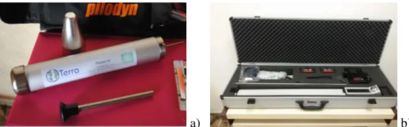
To this test was used a Pilodyn®, model 6J (Figure 4 a.), being that on sound beams were made ten tests in the extension of the beams, and on beams with some kind of degradation were made the same ten tests and five more on the degraded area.
The obtained results were used to make the measurement of average surface hardness and correlate with density of the element [13].
3.5. Drill resistance test
Was used a drill resistance test device, model IML Resi PD 500 (Figure 4 b.), working with
Pilodyn®, on the same sections of the element. Was followed this logic by the necessity of
crossing values and informations of both devices to obtain maximum information about the section under study. The tests were conditioned for the disposal of the elements and the space between beams, having the device been positioned always in the vertical way, and the test was realized from the lower face of the beams.
The importance of this test is related by the possibility of obtain information about the internal state of the elements, and to assess, when necessary, presence and extension of degradation. With final results was allowed to confirm residual sections obtained by visual inspection, which has conditioned the acceptance or not of the beams to structural assessment.
a) b)
Figure 4. a) Impact resistance test device: Pilodyn®- Model 6J b) Drill resistance test device: Model IML Resi PD 500
4. STRUCTURAL ASSESSMENT 4.1. Loadings and supports design
Was adopted a loading and supports simplified system, on which considered that beams are simply supported and loads are uniformly distributed in all beams. This decision was taken because is known the behavior of this system. The beams are requested by its own-weight, the own-weight of the layer in its influence area, and by the existence or not of imposed load, according to the hypothesis under study. Were also considered the residual sections of all beams that the design is so close as possible to the actual conditions of the structure.
4.2. Ultimate limit test
A verification of the structure elements was done to the ultimate limit of simple bending and to the shear. The verification has as objective to determine if the strength capacity of the elements is enough to support the actions imposed by loading. The effort of lateral buckling was considered as prevented due to the dowels between beams.
Relatively to simple bending, the most stressed point in the beams is mid-span where the bending moment is maximal. For shear tension, the critical point in beams will be on supports, because at those points the shear force has its maximum values.
The critical sections were attributed in consideration of the effort to design, and the most stressed point. A comparative study between the residual section and the section without defects was also done for the beams that had lost of section. By this way was possible understand the severity of the registered section loss.
4.1. Serviceability limit state
The verification of the structure elements to deformation was made. According to the loading system and supports, it is expected that the maximal deformation will be verified in mid-span. As observer for other efforts that have been designed, was made the design with the dimensions of critical section, and with the dimension of the defect free section. Because it is a wood structure in service, was considered that should be observed some effects of instantaneous deformation due loadings and long-time deflection due creep effects.
5. RESULTS AND DISCUSSION
To the assessment realized element by element, was followed an inspection record, with all relevant parameters from the element, as well some space to photos report.
According to the standard NP EN 335-1,2:2013 [14], was attributed to the structure the hazard class 2, for precaution because the structure has occasional wetting risk, caused by problems in window frames or / and lack of roof insolation.
5.1. Water content
It is concluded that the wood was dry at the date of assessment (June –July 2015), with a water content near 12%. If these results will be maintained, there is no possibility of developing of biological degradation by rot fungi or subterranean termites.
5.2. Grading rules 5.2.1. Knots
The assessment of the develop of knots in the interior of the piece was made, using the marginal KAR and total KAR (Figure 6), wherein the importance of the first one attaches to the bending efforts, in the face where the wood is towing. All knots of all beams were assessed. The partial
Figure 5.- Marginal and total KAR
5.2.3. Slope of grain
Was made some measures on enough length (+/- 50cm), without defects that could affect the grain develop. The partial results are shown in table 1.
5.2.4. Rate of growth
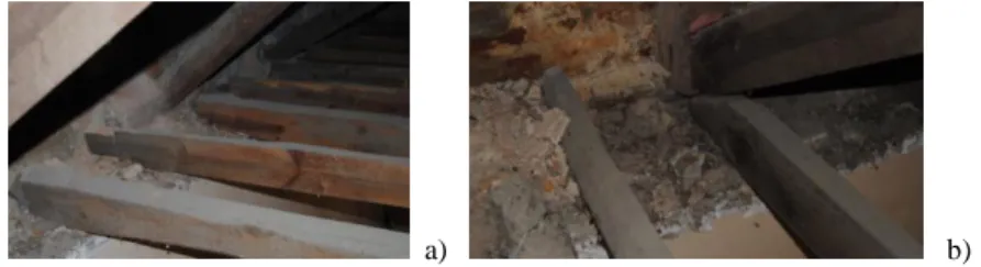
The rate of growth was the most complex parameter to determine because the measurements had to be made on the top of the pieces or in the faces where the presence of pith is visible. Almost all the tops are against the walls (Figure 7 a. and b.), so the observation was not allowed and that ones that were not, were really dirties, so it was not possible to count the growth rings. However, 7 of the 27 analyzed beams had pith on their faces, so only this beams were assessed. The partial results are in table 1.
a) b) Figure 6. a) and b) Beams' ends
5.2.5. Visual grades and strength classes
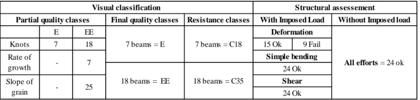
Thru the visual grades assigned by the standard NP 4305:1995 [3], the parameter that was conditioned the final grading was the knots. This way, 7 of the 27 assessed beams have visual grades E (structures) and the others have visual grades EE (special structures).
With this result, and with standard EN 338:2009 [4], and NP EN 1912:2013 [5], was attributed to the beams with grade E (structures) the strength class C 18, and to the beams with grade EE (special structures) the strength class C 35, and respective associate characteristics values, as can see in table 1.
5.3. Impact resistance test
With Pilodyn®’s test was obtained to sound beams or with no determinate biological degradation, a medium depth penetration of 16 mm and to the beams with some kind of detected biological degradation, 26 mm. To obtain the density value were only accepted the values of sound beams. A correlation established by Henriques [13] was followed, where Pilodyn®’s test results are related with the density of this specie. Keeping the non-destructive character of the study, this was the way founded to obtain density. Was estimated a medium value of 570 kg/m³,
which is accordingly to the density of Maritime pine (Pinus pinaster): 530-600 kg/m³ [15], but superior to the medium values established by EN 338, both to C18 class and C35 class.
5.4. Drill resistance test
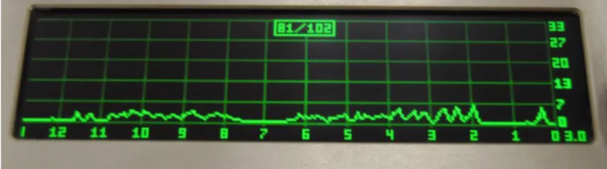
In this test was possible to determinate nonexistence of residual section in 2 beams in study. The needle’s device passed through all section without any type of resistance (Figure 8), what leading to believe that section is not composed by really sound wood, but mainly for degraded wood, that only keeps cohesion and enough resistance to maintain the position of the element.
Figure 7. Drill resistance profile
This result is important to show that is absolutely necessary to complement the obtained results by visual inspection, which gives an outside perspective of the elements, with methodologies to assess the quality and internal state of wood.
5.5. Structural assessment
In the structural assessment of the elements was admitted two hypothesis of design, to each limit state: 1. maintenance of use; 2. changing of use - the structure pass to be used as support to a new storage place, with an imposed load increase of 2, 0 kN/m³ [7]. In the first hypothesis the structure is used only as ceiling, don’t suffering for this reason any imposed load increase. Were also used different values of density: experimental, where was considered the values obtained with impact resistance test and characteristics values, attributed by EN 338 to the strenght classes [4]. In beams where the woodworm (Anobium punctatum) was detected, a 15% reduction was made on characteristic strength parameters of the beams, in such a way to simulate the loss of strength capacity provoked by this kind of biological damage [16].
In terms of results, the limit state on more beams did not verify the safety was the serviceability limit state of deformation, in which 9 beams did not verified. This result is possible to justify by high-slenderness, caused by small initial dimensions, or by loss of section caused by biological degradation. The non-verification was just in the hypothesis of changing of use, with the imposed load increase, both with experience density design and with density attributed by standards. Final results are shown in table 1.
Table 1. Final results – Visual grades and structural assessment
Relatively to the ultimate limit state of simple bending and shear, all beams check safety to any service conditions. Contrary to what happens with deformation, the slenderness acts positively, because slender elements have a small own-weight, so they are not too requested.
6. CONCLUSIONS
With the obtained results by assessment and structural design, it was concluded that the fragile appearance is not necessary and sufficient condition so that does not have the necessary safety conditions. To the 28 beams belonging to the ceiling structure, only one was not assessed, due to existent gap and misalignment in the supports that did not offered safety conditions. Two beams were not structurally evaluated, because they did not had residual section (this conclusion was obtained by drill resistance test). To the 25 assessed beams, 7 corresponded of a quality class E (structures) and strength class C18, and the others to a quality class EE (special structures) and strength class C35. After the structural verification by EN 1195:2004, 9 beams failed to verify the serviceability limit state of deformation, changing the conditions of use (increase of imposed load), because with the hypothesis of use maintenance the verification is achieved. To simple bending and shear safety verification is always achieved.
In general way, some structure elements have significant loss of effective sections, with a ma-ximum value of 39%, comparing to initial section. This loss of section is caused just by wood boring insect (Hylotrupes bajulus L.), without evidence of rot fungi. On a posterior step, it will be necessary to determinate with more precision residual sections, that will allow the results maintenance, and consequently the safety’ users and the structure itself. It is also im-portant to refer poor condition of joints and supports that, apart from biological damage also have gaps and misalignment to the pieces axis. In a rehabilitation solution, supports must be reinforced, 3 beams must be replaced and 7 must be reinforced, if it wants to use the attic.
The most important constraints of this study were the fact that that takes place in height, because it is not accessible from superior part, increasing slowness and the risk of accidents. As it is an old structure with openings to the exterior, the present of dust and biological waste was constant. These constraints alert to the specificities of the work of inspection structures in service, wherein conditions to find will always be an unknown, with which the technician that will realize the inspection must take in to account, and to which will have to prepare and find solutions to overcome difficulties.
Resistance classes
E EE
Knots 7 18 15 Ok 9 Fail
Partial quality classes
Rate of growth Slope of grain - 7 - 25 18 beams = C35
Visual classification Structural assessement
18 beams = EE
With Imposed Load Without Imposed load Deformation Simple bending 24 Ok Shear 24 Ok All efforts = 24 ok 7 beams = C18
Final quality classes
REFERENCES
[1] V. Cóias, “Reabilitação Urbana” Observatório do Emprego e Formação Profissional e GeCorpa, Lisboa, 2011;
[2] R. Anthony, K. Dugan, D. Anthony, “A grading protocol for structural lumber and timber in historic structures”, APT Bulletin: Journal of preservation technology / 40:2, USA, 2009; [3] NP 4305:1995, “Madeira serrada de pinheiro bravo para estruturas. Classificação
visual”, Lisboa: IPQ, 1995;
[4] EN 338:2009, “Structural timber; Strength clases”, Bruxelles: CEN, 2009;
[5] NP EN 1912:2013, “Madeira para estruturas. Classes de resistência. Atribuição de classes de qualidade e espécies”, Lisboa: IPQ, 2013;
[6] H.Cruz, L. Nunes, “A madeira como material de construção”, Lisboa: LNEC, 2008; [7] EN 1995:2004, “Design of Timber Structures”, Bruxelles: CEN, 2004;
[8] H. Cruz, D. Yeomans, E. Tsakanika, N. Macchioni, A. Jorissen, M. Touza, M. Mannucci, P. Lourenço, “Guidelines for On-Site Assessment of Historic Timber Structures”, International Journal of Architectural Heritage: Conservation, Analysis, and Restoration. 2015. 9:3,277-289;
[9] J. Machado, A. Dias, H. Cruz, J. Custódio, P. Palma, “Avaliação, Conservação e Reforço de Estruturas de Suporte de Madeira”, Lisboa, 2009,
[10] J. Branco, H. Sousa, “Métodos de Inspeção e Classificação visual de elementos de madeira”, Guimarães: Universidade do Minho (Escola de Engenharia), 2014
[11] A. Feio, P. Lourenço, “Possibilidades e aplicações de ensaios não destrutivos”, Encontro sobre a madeira e suas aplicações nobres - Bem utilizar a madeira; Universidade do Minho, INETI, 2005;
[12] H. Sousa, J. Branco, P. Lourenço, “Da inspeção à avaliação de segurança na reabilitação de estruturas de madeira”, Seminário “Intervir em construções existentes de madeira”, Guimarães, Portugal, Junho 2014, pp. 57-70. ISBN: 978-972-8692-86-5;
[13] D. Henriques, “Tratamento e consolidação de madeira de pinho degradada em elementos estruturais de edifícios antigos”, Lisboa: Instituto Superior Técnico (IST), 2011, PhD thesis; [14] EN 335-1,2:2013, “Durability of wood and wood-based products. Use classes: definitions,
application to solid wood and wood-based products. Part 1 and 2”, Bruxelles: CEN, 2013; [15] LNEC, “Ficha M2: Pinho bravo para estruturas. Série Madeira para construção, Lisboa”, 1997; [16] S. Mendes, “Degradação da madeira por caruncho em edifícios antigos. Uma análise