Paulo Renato Carvalho Ribeiro*, Sérgio Henrique Casarim Fernandes**, Gustavo Saggioro Oliveira***
Introduction: Rapid canine retraction through distraction of the periodontal ligament is a tooth movement technique that allows space closure of first premolar extraction space within a period of two to three weeks while providing significant reduction in
orth-odontic treatment time. Objective: To propose changes in the original surgical technique
and in the placement of distractors. Conclusions: Rapid canine retraction is a technique
that provides significant reduction in orthodontic treatment time. Changes in the surgi-cal technique provided greater speed and safety in surgery. As a minimum benefit, when positioned palatally, distractors helped to preserve the buccal bone plate and prevented canine proclination.
Abstract
Keywords: Distraction osteogenesis. Tooth movement. Orthodontic space closure.
* Specialist in Orthodontics, Rio de Janeiro State University (UERJ). MSc in TMD/OFP – SLM, Campinas. Professor, Orthodontics Specialization Program, ABO, Juiz de Fora (Minas Gerais State, Brazil). Diplomate of the Brazilian Board of Orthodontics (BBO).
** Specialist and MSc in Orthodontics, COP / PUC-MG. Coordinator, Specialization Program in Orthodontics, Brazilian Dental Association (ABO), Juiz de Fora (Minas Gerais State, Brazil). Diplomate of the Brazilian Board of Orthodontics (BBO).
*** Specialist in Oral and Maxillofacial Surgery, FOB-USP. MSc in Oral and Maxillofacial Prosthetics - UNESP. Professor, Orthodontics Specialization Program, ABO, Juiz de Fora (Minas Gerais State, Brazil).
IntrOduCtIOn
Distraction osteogenesis is a process whereby new bone is grown by mechanically stretching a pre-existing bone tissue. It was made popular in
studies by Ilizarov,6 who showed in hundreds of
pa-tients that new bone could be formed after surgical corticotomy followed by distraction osteogenesis.
In 1998, Liou and Huang11 introduced the
concept of distraction osteogenesis in tooth move-ment. These authors noted that the process of periodontal ligament osteogenesis during tooth
movement induced by orthodontic forces is simi-lar to that of the midpalatal suture during rapid palatal expansion performed for crossbite correc-tion. The key difference is in the amount of move-ment. While in orthodontic tooth movement the teeth move at a rate of approximately 1 mm per
month,14,15 in rapid palatal expansion the suture is
first premolar extraction. This technique has been named dental distraction (DD).
In 2002, Kisnisci et al8 introduced another
technique for rapid canine retraction. In this approach, known as dentoalveolar distraction (DAD), the segment that contains the canine is transported as a bone block. It differs from the
technique advanced by Liou and Huang11 to
the extent that the periodontal ligament is not stretched. They performed a bone separation from the bone block containing the canine using corticotomies to allow the tooth to move along with the bone that surrounds it through a distrac-tion osteogenesis process.
Regardless of the technique, Rapid Canine Retraction (RCR) has proven well suited for the following clinical situations: Severe crowd-ing, Class II Division 1 malocclusions, bialveolar protrusion, root shortening and malformation, as well as in patients presenting with periodontal
problems.2,3,7,8,11,16 These indications are
justi-fied by the fact that, since tooth movement is accomplished very quickly, with the canine be-ing completely distalized in about two to three weeks without anchorage loss, the remaining space can be used for the rapid resolution of crowding. During conventional orthodontic movement, the process of root resorption only begins two or three weeks after the application of a given force, and may continue for as long as
this force continues to be delivered.9,11,15
More-over, since RCR allows canines to complete all distal movement while the remaining teeth are
still stationary,4 both the mesial movement of
molars, i.e., loss of anchorage, and root resorp-tion either have not yet taken place or are still
just beginning.7,8,11,12,13,16,17 This benefits those
patients who require premolar extractions and present with major periodontal issues.
RCR features the following key advantages: A significant reduction in treatment time from 6 to 9 months, elimination of intra or extraoral anchorage during the procedure, which ensures nearly
com-plete anchorage preservation, added to the fact that it does not damage the periodontium, nor does it affect pulp vitality.2,3,8,10,11,16,17,18 Disadvantages
in-clude the need for a specific surgical procedure and a supervised activation protocol, in addition to dif-ficulties in fabricating distractors using Hyrax-type expanders, as devices suitable for this purpose are not yet available on the domestic market.
The aim of this study was to suggest changes to the surgical technique and the placement of dis-tractors used in RCR, and demonstrate through clinical cases the reduction in treatment time af-forded by this new tooth movement protocol.
dIStrACtOr FABrICAtIOn
The distractor has been fabricated in the
man-ner described by Faber2 from a conventional
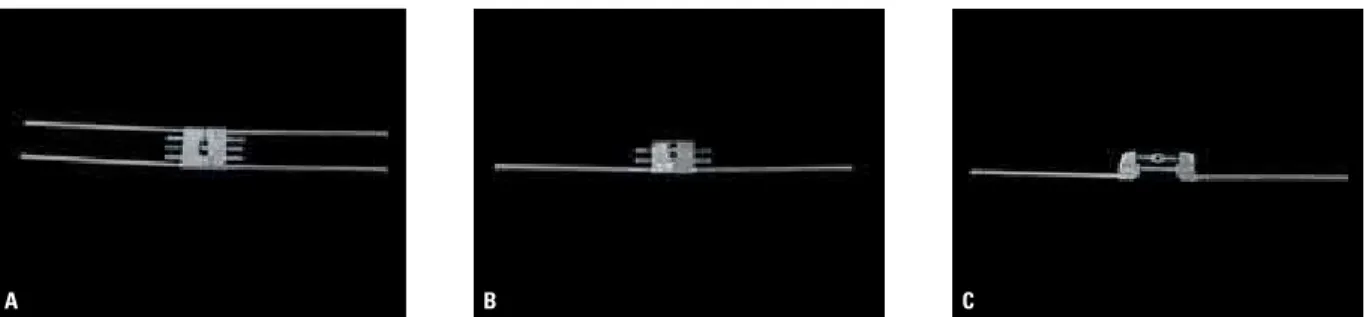
Hy-rax expander. The latter should be opened accord-ing to the number of millimeters that one wishes the canines to distalize, plus at least 2 mm. Prefer-ably, a 13 mm screw should be used, which due to its greater length provides greater stability after opening. A longitudinal section is performed elim-inating one of the rods of the Hyrax and the sharp edges are then rounded off (Fig 1). Proper polish-ing is required to ensure greater patient comfort.
Bands are fabricated for the canines and first molars, and a transfer impression is made to allow the welding of the distractor to the bands once these have been positioned on the working model. The original arrow on the screw should be point-ing towards occlusal to facilitate activation and prevent forces from moving the distractor during the activation process. Thus, as activations will be made in the opposite direction of the arrow, it de-creases the likelihood that the device be displaced.
After verifying that the distractor is properly installed, but before cementing it, it is important that the screw be once again completely closed and opened. To this end, an anti rust spray for use
on screws is applied (White Lub® - Sema
A B C
A B C D
A B C
OrIGInAL SurGICAL tECHnIQuE
During surgery, as originally described by Liou
and Huang11 in 1998, the first step to be
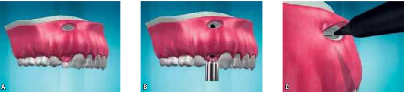
per-formed is premolar extraction (Fig 2A). Then the premolar alveoli are deepened with a round bur until the entire length of the canine is exceeded by about 2 mm (Fig 2B). The interdental septum
Cotia/SP/Brazil). Initially, two vertical grooves are made, one at the buccal edge and one in the palatine bone on the alveolar wall (Fig 3A). These corticotomies are then interconnected by a third (horizontal) corticotomy at its base, performed through intra-alveolar access (Fig 3B). Once the structure of the interdental septum is thus weak-ened, it facilitates canine movement (Fig 3C).
FIGURE 1 - Distractor fabrication: Original Hyrax screw (A), removal of one rod (B), and opening with edges which were rounded (C).
FIGURE 3 - Buccal and palatal vertical corticotomies (A); performance of horizontal corticotomy through intra-alveolar access (B) and occlusal view of prepared alveolus and three corticotomies (C).
A B C
MOdIFIEd SurGICAL tECHnIQuE FOr tHE uPPEr ArCH
After it was observed, in some cases, that the maxillary sinus was too close to the roots of premolars and canines, a slight modification in the surgical technique was proposed in 2007. Through an opening made in the buccal bone plate above the apex of the first premolar the sinus membrane was lifted to avoid the risk of
injuries to this structure.16
After noting the ease of access in performing the buccal access, and considering the existence of bone fenestrations in the premolar region due to the thinness of the buccal bone plate in this region, this modification was incorporated in or-der to minimize the risk of injury to the root of the canine. This risk is due to technical difficulties involved in performing a horizontal corticotomy (above the apex of the canine) by intra-alveolar access in the upper arch (Fig 4).
After premolar extraction, before starting to deepen the alveolus, a 1.5 cm crescent-shaped incision is made in the alveolar mucosa above the root of the first premolar. By removing the periosteum the buccal bone plate is exposed. Normally, one finds an extremely thin cortex with some fenestrations already present at the extraction site, which facilitates the opening of a bone chamber (Fig 5A). From this opening, one can directly observe the deepening of the socket, as described above (Fig 5B). By increas-ing this openincreas-ing in the apical direction, one can also accomplish through it, under direct vision,
a horizontal corticotomy above the apex of the canine without risks (Fig 5C).
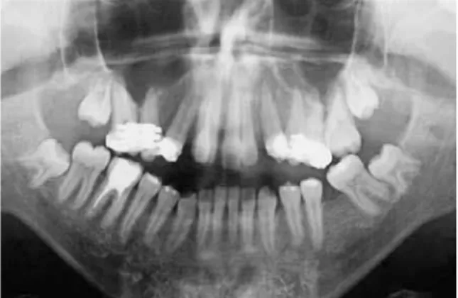
This modification imparts increased speed and security to the surgery, although it does not completely eliminate the need for transoperative radiographs to verify that the alveolus is properly deepened above the apex of the canine. Such ra-diographs (Fig 6) are essential to ensure freedom from bone interference in the apical third. Should this not occur, regardless of the technique, the ca-nine will not undergo bodily movement and will simply incline distally (Fig 7), which will cause the procedure to fail.
FIGURE 4 - Lateral view indicating difficulty in performing horizontal cor-ticotomy via intra-alveolar access.
FIGURE 6 - Transoperative x-ray showing deepening of the tooth socket above canine apex.
FIGURE 7 - Panoramic x-ray indicating steep canine inclination after RCR due to difficulty in surgical technique.
ACtIVAtIOn PrOtOCOL
Distractor activation can be initiated immedi-ately after surgery or after a latency period of up to seven days. The literature is not conclusive in
this respect.1,2,3,7,8,11,16,17 The authors of this article
have used this latency period in cases where the procedure was more invasive with considerable tissue manipulation.
Activations are always performed at the rate of 0.75 mm per day (three turns on the screw) at once, or divided into three activations of 0.25 mm
during the day, for patient comfort.2,16 The
pro-cess is painless and patients only report discom-fort or pressure that dissipates within minutes.
BIOMECHAnICAL COnSIdErAtIOnS
Although no specific work in the literature has ever evaluated the biomechanics of canine move-ment using this technique some important obser-vations can be made based on the evaluation of cases treated by the authors.
According to the original work by Liou and
Huang11, which was confirmed by other
au-thors,1,2,8,13,17,18 canines experience an average
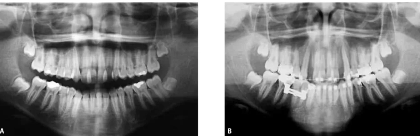
in-clination of 15 to 20 degrees during distalization. This can be confirmed both in panoramic radio-graphs (Fig 8), and in Cone-Beam CT (Fig 9). This inclination, which decreases root apex movement, and therefore decreases neurovascular bundle
stretching may explain why no endodontic com-plications arise when using this technique.
In the vertical plane a significant extrusion of canines during retraction was clinically observed (Fig 10). To avoid inadvertent trauma until it is safe to perform a suitable leveling of the canines, it is necessary in some cases to temporarily raise the bite using glass ionomer cement (GIC) on molars during the procedure.
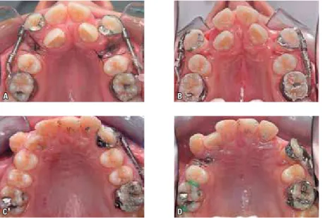
In the transverse plane, with the use of distrac-tors placed through buccal access, distal rotation was observed, as well as canine proclination. This displacement simulates canine movement when using a segmented arch (“T” loop) for distalization in conventional orthodontic mechanics, without adequate control. Although RCR requires the use of a rigid device (distractor), and despite the exis-tence of a tunnel formed by the buccal and palatal bone plates, since the distractor is positioned too buccally relative to the center of resistance of the canine, it depicts a movement with distal rotation and buccal inclination. In the upper arch, as shown in the occlusal photographs, the main side effect was buccal inclination, and the amount of inclina-tion was directly related to the initial posiinclina-tion of canines in the transverse plane, i.e., the more buc-cal, the greater the final inclination (Fig 11).
A B
A B
A B
FIGURE 8 - Initial (A) and post-RCR (B) panoramic x-rays in upper arch showing change in axial inclination of canines.
FIGURE 9 - Panoramic CBCT sections showing change in axial inclination of canines. Before (A) and after (B) RCR.
FIGURE 10 - Initial (A) and post-RCR (B) models showing significant retraction and extrusion of canines.
occurred, albeit with lower magnitude and varia-tion. The fact that the initial axial inclination was more vertical in the lower canines, and the buc-cal bone plate thicker, may be explained by this difference between upper and lower canines. No effects of this procedure were noted on molars.
CHAnGES In dIStrACtOr
In order to avoid proclination of the maxil-lary canines during RCR in cases where canines are well positioned in the buccopalatal direction, or else to move them into the alveolar process in cases where they are initially proclined, some
A B
C D
A B
changes were proposed in the manner in which distractors are fabricated and placed as a measure to prevent buccal inclination of the canines and thus preserve the thin buccal bone plate:
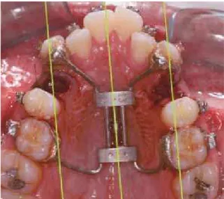
1) Palatal distractor: Made from a Hyrax screw without any clipping. Just turning it 90 degrees allows it to be used for retraction (Fig 13). Rec-ommended for cases where the two canines are initially proclined as it enables moving both teeth into the alveolar process.
2) Asymmetrical palatal distractor: Similar to above, but with the addition of a slight turn when placing the device. Recommended for cas-es where one canine is proclined and the other well positioned (Fig 14).
3) Unilateral palatal distractor: Identical to the
device advocated by Faber2 and described above,
but positioned via the palate. Suitable for canines in any position when the goal is to prevent buccal inclination (Fig 15).
These changes were designed to be a part of the RCR learning curve. Palatal distractors 1 and 2 feature the advantage of being easy to fabri-cate while eliminating the need for trimmings and adjustments, since these devices are nothing but Hyrax screws used in the sagittal direction. However, the cementation process is delicate be-cause of differences between the positions of the canines and molars (mesial and buccal axial incli-nations of canines) and if any interference occurs FIGURE 11 - Occlusal photos of movement of maxillary canines in two different cases, showing
procli-nation. Before (A and B) and after (C and D) RCR.
FIGURE 13 - Occlusal photograph of palatal distractor. Black lines indi-cate canine movement path.
FIGURE 15 - Occlusal photograph of unilateral palatal distractor.
FIGURE 14 - Occlusal photograph of asymmetric palatal distractor. Green lines indicate canine movement path.
in canine movement linked to difficulties in the surgical procedure of deepening the tooth sock-et, simultaneous movement of the right and left canines will be impaired. The unilateral palatal distractor was launched recently and has proved to be a good choice as it allows good control in the transverse plane while maintaining each side independent from each other.
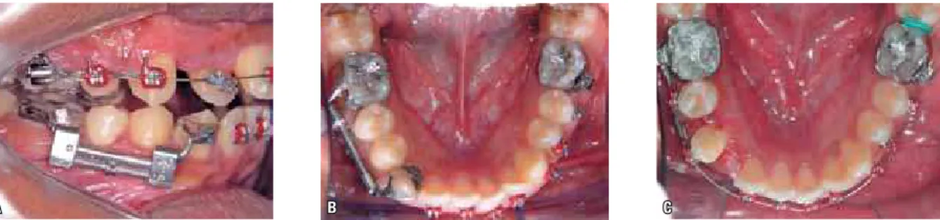
In the lower arch, given the difficulty in us-ing distractor lus-ingually, distractors have been used buccally. To avoid the rotation observed during canine movement, one usually seeks to weld the distractor as far toward the distal side of the ca-nines as possible, thus minimizing the occurrence of rotation (Fig 16).
uSE OF COnE-BEAM COMPutEd tOMOGrAPHY
CT has proven to be an important ally in the study of RCR. It allows for the proper planning of surgical time as it becomes possible to accu-rately determine how much the alveolus needs to be deepened in order to completely eliminate any interference with canine movement (Fig 17).
A B C
Sagittal CT (canine measurement)
FIGURE 16 - Lateral (A) and occlusal (B) photographs showing RCR prior to welding distractor to distal side of canine band. Occlusal photograph taken immediately after RCR showing good canine rotation control (C).
FIGURE 17 - Sagittal CT section for canine measurement. FIGURE 18 - Parasagittal CT scans indicating proximity of maxillary ca-nine root to right maxillary sinus (RMS).
in the deepening procedure. Based on the stan-dardization of the scans and measurements, CT allows a precise comparison between before and after RCR, in addition to serving as a valuable tool for result assessment.
CLInICAL CASES Case 1
The female patient was 20 years and 11 months old and presented for orthodontic treat-ment in March 2008 with a chief complaint of “chin forward and crooked teeth.” The patient had consulted an oral and maxillofacial sur-geon and was aware of her facial involvement. However, she expressed her desire to undergo
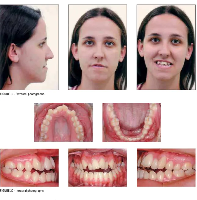
orthognathic surgery as soon as possible, pref-erably before the end of the year. The initial photographs (Fig 19) showed a concave profile with absence of significant asymmetries. On in-traoral examination (Fig 20) an Angle Class III molar relationship was observed, with crossbite and anterior open bite, anterosuperior crowd-ing with incisor proclination and lack of space for the lateral incisors.
In addition to the standard orthodontic re-cords, a Cone-Beam CT scan was requested for evaluating structures, planning surgery and com-paring results (Fig 21).
FIGURE 19 - Extraoral photographs.
FIGURE 20 - Intraoral photographs.
FIGURE 21 - Initial sagittal CT sections. rapid canine retraction to reduce treatment time
during ortho-surgical preparation.
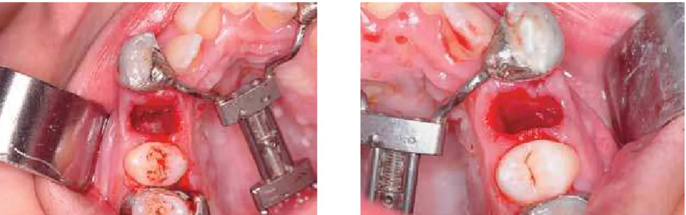
A symmetrical palatal distractor was mount-ed due to the initial buccal position of both ca-nines and surgery was performed to prepare for RCR (Fig 22).
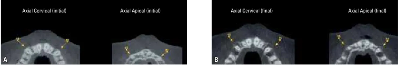
Comparison of CT scans before and after RCR shows adequate biomechanical control in the transverse plane due to the palatal distractor, with total preservation of the buccal bone plate (Fig 24).
Preparation for orthognathic surgery was completed in 7 months, having eliminated all dental compensations, according to initial
plan-and all proposed goals were achieved (Fig 26). The use of RCR enabled rapid alignment and leveling of the upper arch, significantly reduc-ing the duration of orthodontic preparation for surgery, and therefore eliminating the aesthetic discomfort that typically accompanies this type of treatment before primary surgery.
FIGURE 22 - Occlusal photographs of deepening and corticotomies used in surgical technique.
A B
FIGURE 24 - Standardized axial sections of cervical and apical canine regions before (A) and after (B) RCR showing canine movement into alveolar process.
FIGURE 25 - Intra and extraoral preoperative photographs.
FIGURE 26 - Final photographs. Total treatment time was 16 months.
Case 2
A 20 years and 11 months old male pa-tient presented for orthodontic treatment with a chief complaint of “teeth sticking out.” The initial photographs (Fig 27) showed a convex profile with absence of significant asymmetries, and deficient mandible. On intraoral examina-tion, Angle Class II molar relationship was not-ed, in addition to anterior open bite, increased overjet (18 mm), anterosuperior crowding with excessive incisor proclination and mild man-dibular crowding.
Initial planning comprised orthodontic prepa-ration for orthognathic surgery in view of the mandibular deficiency and poor menton-cervical line. In light of the patient’s refusal to undergo surgery, a Class II orthodontic camouflage seemed the best choice, with retroclination of upper inci-sors after extraction of first premolars, total an-chorage control, and interproximal stripping in the lower arch. RCR was thus performed given the outstanding anchorage control afforded by
this technique, in addition to a significant reduc-tion in treatment time. A Cone-Beam CT scan was performed as in the previous case.
First premolars were extracted and RCR prep-aration performed using the conventional tech-nique with the aid of the CT scan. An asymmetric palatal distractor was employed due to the initial positioning of the canines (Fig 28).
The intraoral photographs demonstrated com-plete anchorage control without the aid of any other resources (Fig 29), and the scans revealed canine movement and a well preserved buccal bone plate (Fig 30).
A B
FIGURE 27 - Initial photographs.
A B
FIGURE 29 - Intraoral photographs immediately after RRC, showing orthodontic appliance for alignment, and mini-implants for incisor retraction.
FIGURE 30 - CT axial sections of apical and cervical regions. Initial (A) and post-RCR (B) sections showing canine movement with preservation of buccal bone plate.
FIGURE 31 - Final photographs. Total treatment time was 14 months.
FIGURE 32 - Initial photographs. Case 3
The patient, a 45 years and 11 months old male, presented for orthodontic treatment with a chief complaint of “crooked teeth, especially those two upper ones, which are sticking out,” referred by the periodontics department. The initial pho-tographs (Fig 32) showed a convex profile with absence of significant asymmetries. On intraoral examination, there was a complete canine Class II relationship, severe anterosuperior crowding and moderate crowding in the lower arch. Significant periodontal compromise was also noted, which was confirmed by the coronal view provided by
the panoramic CT scan (Fig 33).
FIGURE 33 - Coronal panoramic view obtained from initial CT scan. enable quick incisor alignment without delivering any forces to the remaining teeth.
A unilateral palatal distractor was inserted and surgery performed on one side at a time at the patient’s request (Fig 35).
After the same procedure had been performed on both sides a fixed self-ligating orthodontic ap-pliance was set up and a heat-activated 0.012-in
37). It should be emphasized that this rapid incisor movement to occupy the canine space is mainly due to the existence of incompletely
mineralized bone tissue,2,7,11,12,16,17 i.e., the
me-sial periodontal ligament of the canine, which in response to having been distended, is on the process of osteogenesis as originally described
by Liou and Huang.11
FIGURE 37 - Intraoral photographs 60 days after RCR.
FIGURE 35 - Occlusal view of palatal distractor on left side, immediately after surgery by modified technique.
gery, and in conjunction with buccal access, renders the procedure faster and safer. When positioned through palatal access, distracters are
biomechani-this treatment protocol are ortho-surgical prepara-tion, patients with severe anterior crowding and patients with periodontal involvement.
1. Bengi AO, Karacay S, Akin E, Olmez H, Okcu KM, Mermut S. Use of zygomatic anchors during rapid canine distalization: a preliminary case report. Angle Orthod. 2006 Jan;76(1):137-47.
2. Faber J. Pergunte a um expert. Rev Clín Ortod Dental Press. 2005 ago-set;4(4):12-21.
3. Faber J, Azevedo RB, Báo SN. Aplicações da distração osteogênica na região dentofacial: o estado da arte. Rev Dental Press Ortod Ortop Facial. 2005 jul-ago;10(4):25-33.
4. Roberts WE. Biomecânica, metabolismo e isiologia óssea
na prática ortodôntica. In: Graber TM, Varnarsdall RL Jr, editores. Ortodontia. Princípios e técnicas atuais. Rio de Janeiro: Guanabara Koogan; 1996. cap 3, p. 175-212. 5. Haas AJ. Palatal expansion: just the beginning of dentofacial
orthopedics. Am J Orthod. 1970 Mar;57(3):219-55. 6. Ilizarov GA. Clinical application of the tension-stress effect
for limb lengthening. Clin Orthop. 1989 Jan;250:8-26. 7. Iseri H, Kisnisci R, Bzizi N, Tuz H. Rapid canine retraction
and orthodontic treatment with dentoalveolar distraction osteogenesis. Am J Orthod Dentofacial Orthop 2005 May;127(5):533-41.
8. Kisnisci RS, Iseri H, Tuz HH, Altug AT. Dentoalveolar distraction osteogenesis for rapid orthodontic canine retraction. J Oral Maxillofac Surg. 2002 Apr;60(4):389-94. 9. Kurol J, Owman-Moll P, Lundgren D. Time-related root
resorption after application of a controlled continuous orthodontic force. Am J Orthod Dentofacial Orthop. 1996 Sept;110(3):303-10.
10. Kurt G, Iseri H, Kisnisci, RS. Rapid tooth movement and orthodontic treatment using dentoalveolar distraction (DAD): long-term (5 years) follow-up of a Class II case. Angle Orthod. 2010 May;80(3):597-606.
11. Liou EJ, Huang CS. Rapid canine retraction through distraction of the periodontal ligament. Am J Orthod Dentofacial Orthop. 1998 Oct;114(4):372-82.
12. Liou EJ, Figueroa AA, Polley JW. Rapid orthodontic tooth movement into newly distracted bone after mandibular distraction osteogenesis in a canine model. Am J Dentofacial Orthop. 2000 Apr;117(4):391-8.
rEFErEnCES
13. Lv T, Kang N, Wang C, Han X, Chen Y, Bai D. Biologic response of rapid tooth movement with periodontal ligament distraction. Am J Orthod Dentofacial Orthop. 2009 Sep;136(3):401-11.
14. Pilon JJGM, Kuijpers-Jagtman AM, Malta JC. Magnitude of orthodontic forces and rate of bodily tooth movement. An experimental study. Am J Dentofacial Orthop. 1996 July;110(1):16-23.
15. Reitan K. Clinical and histological observations on tooth movement during and after orthodontic treatment. Am J Orthod. 1967 Oct;53(4):721-45.
16. Ribeiro PRC, Monteiro SRS, Fernandes SHC, Oliveira GS. Retração rápida de caninos associada ao levantamento do seio maxilar. Rev Dental Press Ortod Ortop Facial. 2007 set-out;12(5):23-33.
17. Sayin S, Bengi AO, Gürton AU, Ortakoglu K. Rapid canine distalization using distraction of the periodontal ligament: a preliminary clinical validation of the original technique. Angle Orthod. 2004 June;74(3):304-15.
18. Sukurica Y, Karaman A, Gürel HG, Dolanmaz D. Rapid canine distalization through segmental alveolar distraction osteogenesis. Angle Orthod. 2007 Mar;77(2):226-36.
Contact address
Paulo Renato Carvalho Ribeiro Rua Oswaldo Cruz 75, Sta. Helena CEP: 36.015-430 - Juiz de Fora / MG, Brazil E-mail: [email protected]