UNIVERSIDADE DA BEIRA INTERIOR
Engenharia
A Comparison of Different Gas Turbine Engines
Ground Vortex Flows
Pedro Alexandre Rodrigues Manquinho
Dissertação para obtenção do Grau de Mestre em
Eng. Aeronáutica
(2º ciclo de estudos)
Orientador: Prof. Doutor Jorge M. M. Barata
Co-orientador: Prof. Doutor André R. R. Silva
Dedicatory
This thesis is dedicated to my family, with particular attention to my mother who took me the first time to see a Public University if memory serves me right whit four or five years of age to my father
Acknowledgment
Here, you would usually thank all who contributed to this work but I will thank all those who contributed to my academic growth, the Department of Aerospace Sciences, to all my teachers but of which I must mention two in particular, Professor. Dr. Jorge M. M. Barata my supervisor and the person I have in great esteem as a human being and academic and Prof. Dr. Andre R. R. Silva who I watched grow as academic with merit and great panache.
Resumo
O design do bocal de admissão do motor é muito importante porque, é um dos componentes do motor directamente em interface com o fluxo em torno do motor e o fluxo de ar interno. A admissão é projectada para dar a quantidade adequada de fluxo de ar necessário as condições de fluxo livre das condições exigidas na entrada do compressor com perda de pressão mínima pelo mecanismo. Quando as perdas de pressão e as distorções de fluxo são muito baixas, o desempenho do motor é ideal, e essa é a razão por que o fluxo de ar tem de ser tão uniforme quanto possível, ao compressor. Esta condição de fluxo de ar é necessária em todas as configurações de voo, inclusive quando a aeronave está manobrando nas tarefas de solo. O desempenho de admissão depende o fluxo de massa entregue para o compressor. O fluxo de massa interno permanece constante do tubo fluxo capturados para o rosto do compressor e supondo que o fluxo seja incompressíveis devido a
velocidades de baixa velocidade, será dada por AiUiAU. Uma vez que o fluxo de massa é
constante e a relação da área está relacionada à proporção de contracção de tubo de fluxo, a
relação da área pode ser expresso como
2 i q D L i A A
. O rácio de captura é controlado pelo
motor, o fluxo de massa do motor, o diâmetro de admissão e a velocidade de fluxo livre. A área definida pelo limite entre o ar que entra no motor e o ar que não é chamada a área de admissão capturada. A taxa de fluxo e a forma de tubo de fluxo variam de acordo com as condições de operação do motor. Perto da configuração estática desde que o ar ambiente está em repouso, o motor acelerar o ar usando o máximo impulso. A aceleração local extrema do fluxo, o bordo de entrada pode levar à separação de fluxo de ar no presente region2, 3. Configuração de crossflow, na forma do tubo do fluxo é modificada perto do bordo. O crossflow leva a um aumento da velocidade de fluxo perto do bordo dependendo da força das origens crossflow de alta velocidade na separação de fluxo, levando a uma perda total da pressão.
i
A
A /
A formação de vórtices de solo depende da potência do motor, altura de admissão de velocidade e o mecanismo de vento e tamanho. Trabalhos publicados anteriores mostram que o fenómeno só pode ocorrer com a presença de uma linha de estagnação entre o solo e a admissão, de que depende do
rácio de velocidade e da altura não-dimensional do eixo motor acima do solo, h/di (Fig. 1).
Em condições estáticas, o fluxo de ar de admissão exigem aumentos e a admissão captura
superficial aumenta em diâmetro e começa a incluindo a terra para trazer o fluxo de ar necessário para a fan4, 5. Normalmente a formação de vórtices de solo é caracterizada por baixa h/di e alta
que corresponde a um mecanismo de funcionamento junto ao solo em uma entrada elevada massa flow6. Assim, o mecanismo de formação de admissão é fortemente dependente da altura do eixo motor acima do solo, a taxa de velocidade e a presença de uma velocidade de upstream. Foram identificados quatro tipos diferentes das condições que conduzem à formação de vórtices de
U Ui/
U
U
i/
solo. Pode ser gerado um vórtice sem vento ambiente e com uma baixa relação h/di (geralmente inferior a um). Devido à proximidade do solo, níveis elevados de sucção abaixo de admissão do motor leva a um forte fluxo debaixo da admissão. Nestas condições, é possível visualizar a admissão do motor e o terreno dois para cima vórtices espiral. Na condição de noventa, afigura-se que as duas vórtices são conversores, e a motricidade é induzida pela camada limite. É um fluxo de vento de frente, quando o ar é sugado para a admissão do motor, o campo de fluxo debaixo da admissão começa a fundir em duas vórtices conversores eretas e um fluxo rápido em direcção oposta do vento aparece entre eles. Para razões altas de velocidade (> 20) o sentido de rotação dos dois vórtices alterna para o mesmo mecanismo não-vento. Com um 90 ° crossflow dois tipos diferentes de vórtices aparecem em torno da admissão: um vórtice de entrada e um vórtice à direita.
Quando a admissão de motor está orientada em um ângulo de Guinada de 90 ° e com a presença de crossflow com upstream longe vorticidae vertical, há a formação de um vórtice único dentro da admissão. Neste caso, o sentido de rotação do vortex é oposto do ambiente vorticidade. Outros mecanismos de formação também existem e podem ser considerados como combinações os anteriores que levam a um grande número de combinações possíveis que são responsáveis para a necessidade de mais estudos compreender toda a física envolvida.
Ferramentas de CFD foram aplicadas recentemente para a compreensão do vortex com relativo sucesso. Nakayama & Jones10 usado métodos painel para simular a entrada e modos interacção, notando que a velocidade do vento necessária para fundir o vórtice afastado era inferior a medida experimentalmente.
Barata et al.11 relatório cálculos de Navier-Stokes e previu com êxito os fenómenos de vórtice de solo usando as condições operacionais reais para o caso do motor Trent 900. A formação de vórtice de solo no fluxo de ventos irrotational é analisada em detalhe para esta configuração, e a formação do vortex à direita foi associada a um fluxo muito complexo.
No presente livro, o trabalho anterior de Barata et al.11 é estendido para incluir vários motores que estão sendo usados no presente. Os fluxos de vórtice de solo produzidos pelos motores diferentes são comparados e discutidos para cada condição operacional.
Palavras-chave
Admissão, vórtice, solo, fluxo, motor, vento cruzado.
Abstract
The design of an engine intake is very important because, it is one of the engine components that directly interface with the flow around the engine and the internal airflow. The inlet is designed to give the appropriate amount of airflow required from the free-stream conditions to the conditions required at the entrance of the compressor with minimal pressure loss by the engine1. When the pressure losses and the flow distortions are very low, the performance of the engine is optimal, and that is the reason why the airflow has to be as uniform as possible when entering into the
compressor. This airflow condition is necessary in all flight configurations including when the aircraft is maneuvering on ground tasks. The intake performance depends on the mass-flow delivered to the compressor. The internal mass-flow stays constant from the captured stream tube to the compressor face and assuming that the flow is incompressible due to low speed velocities, it
will be given by . Since the mass-flow is constant and the area ratio is related to the
stream tube contraction ratio, the area ratio can be expressed as
AU U Ai i 2 i q i D L A A
. The capture ratio is controlled by the engine, the engine mass-flow, the inlet diameter and the free-stream velocity. The area defined by the boundary between the air that enters in the engine and the air that does not is called the intake captured area. The flow ratio and the stream-tube shape vary with the operation conditions of the aircraft engine. In near static configuration since the ambient air is at rest, the engine must accelerate the air using maximum thrust. The extreme local
acceleration of the flow at the inlet lip can lead to airflow separation in this region2,3. In cross-wind
configuration, the shape of the stream tube is modified near the lip. The cross-flow leads to an increase in the flow velocity near the lip depending on the strength of the cross-flow, high velocity origins in flow separation leading to a total pressure loss at the engine fan.
i
A
A /
The formation of ground vortices depends on engine power, wind velocity and engine inlet height and size. Previous published work show that the phenomenon can only occur with the presence of a stagnation streamline between the ground and the intake which is dependent on the velocity ratio
and the non-dimensional height of the engine axis above the ground, h/Di (Fig. 1). In static
conditions, the inlet airflow demand increases, and the inlet capture surface increases in diameter
and starts including the ground to bring the necessary airflow to the fan4,5. Typically the formation
of ground vortices is characterized by low h/Di and high that corresponds to an engine
operating close to the ground at a high inlet mass flow6. Hence, the mechanism of intake formation
is strongly dependant of the height of the engine axis above the ground, the velocity ratio and the presence of an upstream velocity.
U Ui/
U
U
i/
xFour different types of conditions leading to the formation of inlet ground vortices have been
identified. A vortex can be generated without ambient wind and with a low ratio h/Di (typically less
than one). Due to the ground proximity, high levels of suction beneath the engine inlet leads into a
strong flow underneath the inlet upstream towards the intake lip7. In these conditions, it is possible
to visualize at the engine intake and at the ground two upward spiraling vortices. Under no-wind condition, it appears that the two vortices are counter-rotating, and the vorticity is induced by the boundary layer. Is a head-wind flow, when the air is sucked into the engine inlet, the flow field underneath the intake starts to roll up into two upright counter-rotating vortices and a fast flow
into the opposite direction of the wind appears between them8,9. For high velocity ratios (>20) the
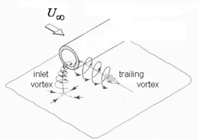
sense of rotation of the two vortices switches to the same as in the no-wind mechanism. With a 90° cross-wind two different kinds of vortices appear around the intake: an inlet vortex and a trailing vortex (Fig.3). When the engine intake is oriented at a 90° yaw angle and with the presence of cross-wind with far upstream vertical vorticity, there is the formation of a single vortex inside the intake. In this case the sense of rotation of the vortex is opposite to the ambient vorticity. Other mechanisms of formation also exist and can be considered as combinations of the previous ones that lead to a large number of possible combinations that are responsible for the need of more studies in order to understand all the physics involved.
CFD tools have been applied recently to the understanding of the ground vortex with relative
success. Nakayama & Jones10 used panel methods to simulate the inlet and ground interaction,
noting that the wind speed needed to blow the vortex away was lower than the measured
experimentally. Barata et al.11 report Navier-Stokes calculations and predicted successfully the
ground vortex phenomena using real operational conditions for the case of the engine Trent 900. The ground vortex formation in irrotational crosswind flow is analyzed in detail for this
configuration, and the formation of the trailing vortex was associated to a very complex flow.
In the present paper the previous work of Barata et al.11 is extended to include several engines that
are being used in the present. The ground vortex flows produced by different engines are compared and discussed for each operational condition.
Keywords
Índice
Dedicatory...iii Agradecimentos ... Erro! Marcador não definido. Resumo ...vii Palavras-chave ...viii Abstract...x Keywords...xi Chapter 1 ... 1 Introduction... 1 Chapter 2 ... 4 Mathematical Model... 4 Chapter 3 ... 7 Results ... 7 Chapter 4 ... 31 Conclusions... 31 References ... 32Nomenclature
i A = intake area A= frequency of oscillation of the ground vortex
Di = inner diameter of the intake
h = height of the engine axis above the ground
k = turbulent kinetic energy
Lq = intake stream tube length
m = mass flow
Ui = intake throat velocity
U = free stream velocity
V = tangential velocity Γ = vortex circulation ζ = vorticity ρ = density = dynamic viscosity = kinematic viscosity
T = turbulent kinematic viscosity
= any dependent variable
Chapter 1
Introduction
The design of an engine intake is a very important part of the aircraft engine design because it influences the overall performance. The inlet is designed to give the appropriate amount of airflow required from the free-stream conditions to the conditions required at the entrance of the
compressor with minimal pressure loss by the engine1. Flow distortions at the inlet cause
conditions that were not taken into account during the design process and usually represent a negative influence. So, to obtain the optimal engine conditions the airflow must be as uniform as possible when entering the compressor. This airflow condition is necessary in all flight
configurations including when the aircraft is maneuvering on ground tasks where hazardous suction
of objects may occur.
Figure 1. Ground vortex formation.
The intake performance depends on the mass-flow delivered to the compressor. The internal mass-flow stays constant from the captured stream tube to the compressor face and assuming that
the flow is incompressible due to low speed velocities, it will be given by . Since
the mass-flow is constant and the area ratio is related to the stream tube contraction ratio, the
area ratio can be expressed as
A U i U i A 2 i D q L i A A
. The capture ratio is controlled by the
engine, the engine mass-flow, the inlet diameter and the free-stream velocity. The area defined by the boundary between the air that enters in the engine and the air that does not is called the intake captured area. The flow ratio and the stream-tube shape vary with the operation conditions of the aircraft engine. In near static configuration since the ambient air is at rest, the engine must accelerate the air using maximum thrust. The extreme local acceleration of the flow at the inlet
lip can lead to airflow separation in this region2,3. In cross-wind configuration, the shape of the
i A / A
stream tube is modified near the lip. The cross-flow leads to an increase in the flow velocity near the lip depending on the strength of the cross-flow, high velocity origins in flow separation leading to a total pressure loss at the engine fan.
The formation of ground vortices depends on engine power, wind velocity and engine inlet height and size. Previous published work show that the phenomenon can only occur with the presence of a stagnation streamline between the ground and the intake which is dependent on the velocity
ratio and the non-dimensional height of the engine axis above the ground, h/Di (Fig. 1). In
static conditions, the inlet airflow demand increases, and the inlet capture surface increases in
diameter and starts including the ground to bring the necessary airflow to the fan4,5. Typically the
formation of ground vortices is characterized by low h/Di and high that corresponds to an
engine operating close to the ground at a high inlet mass flow6. Hence, the mechanism of intake
formation is strongly dependant of the height of the engine axis above the ground, the velocity ratio and the presence of an upstream velocity.
U / i U U / i U
Four different types of conditions leading to the formation of inlet ground vortices have been
identified. A vortex can be generated without ambient wind and with a low ratio h/Di (typically
less than one). Due to the ground proximity, high levels of suction beneath the engine inlet leads
into a strong flow underneath the inlet upstream towards the intake lip7. In these conditions, it is
possible to visualize at the engine intake and at the ground two upward spiraling vortices. Under no-wind condition, it appears that the two vortices are counter-rotating, and the vorticity is induced by the boundary layer. Is a head-wind flow, when the air is sucked into the engine inlet, the flow field underneath the intake starts to roll up into two upright counter-rotating vortices
and a fast flow into the opposite direction of the wind appears between them8,9. For high velocity
ratios (>20) the sense of rotation of the two vortices switches to the same as in the no-wind mechanism. With a 90° cross-wind two different kinds of vortices appear around the intake: an inlet vortex and a trailing vortex (Fig. 2). When the engine intake is oriented at a 90° yaw angle and with the presence of cross-wind with far upstream vertical vorticity, there is the formation of a single vortex inside the intake. In this case the sense of rotation of the vortex is opposite to the ambient vorticity.
Figure 2. Sense of rotation of the inlet vortex and the trailing vortex (sketch adapted from Ref. 9).
Other mechanisms of formation also exist and can be considered as combinations of the previous ones that lead to a large number of possible combinations that are responsible for the need of more studies in order to understand all the physics involved. CFD tools have been applied recently
to the understanding of the ground vortex with relative success. Nakayama & Jones10 used panel
methods to simulate the inlet and ground interaction, noting that the wind speed needed to blow
the vortex away was lower than the measured experimentally. Barata et al.11 report Reynolds
Averaged Navier-Stokes calculations and predicted successfully the ground vortex phenomena using real operational conditions for the case of the engine Trent 900. The ground vortex formation in irrotational crosswind flow is analyzed in detail for this configuration and engine, and the formation of the trailing vortex was associated to a very complex flow.
Chapter 2
Mathematical Model
The mathematical model used in the present study is described in detail in Ref. 11 and only the main features will be summarized here. The time averaged partial differential equations governing the steady, uniform-density isothermal three-dimensional flow
j ' u i' u j X i U j X i X P j X i U j U (1) and the continuity equation,0 i X i U j U (2)
where solved together with the equations of transport of the turbulent kinetic energy and
dissipation rate of the two-equation “k-” model10
j X i U j ' u i' u j X k k T j X j X k j U (5) k 2 2 C j X i U j ' u i' u k 1 C j X T j X j X j U
(6)where C1 and C2 are additional dimensionless model constants, and k and are the turbulent
Prandtl numbers for kinetic energy and turbulent dissipation. The Reynolds stresses are expressed as
ij k 3 2 i X j U j X i U T j ' u i' u
(3)where T is the turbulence kinematic viscosity, which is derived from the turbulence model and
expressed by Cµk2/ε.
The solution of the governing equations was obtained using a quadratic finite-difference method12
that used discretized algebraic equations deduced from the exact differential equations that they represent.
The solution procedure is based on the SIMPLE algorithm widely used and reported in the
literature (e.g. Ref. 13). It uses the staggered grid arrangement and a guess and correct procedure field such that the solution of the momentum equations satisfies continuity.
The computational domain has six boundaries where dependent values are specified: a free stream plane, a symmetry plane, and a solid wall. On the symmetry plane, the normal velocity vanishes, and the normal derivates of the other variables are zero. At the solid surface, the wall function
method14 is used to prescribe the boundary conditions for the velocity and turbulence quantities,
assuming that the turbulence is in state of local equilibrium. The free stream plane is located at
Z=0 and corresponds to the crossflow conditions. The engine intake boundary is represented by a
right angled polygon and the mass flow rates and the momentum are matched to the experimental values. The intake represents a 1/1th scale model with a diameter that corresponds to each particular engine. The axis of the engine is located at a distance above the ground (h), which corresponds to the specific clearance distance. All the tests were performed for the case of irrotational crosswind, and the other conditions are shown in Table 1. The domain of solution, their dimensions and the system of axes are represented in Fig.3
a)
Engine Diameter (m) Clearance Distance Mass Flow (lb/s) Mass Flow (Kg/s) Radius (m) Inlet Velocity (m/s) H (m) cf6‐50 2,6670 0,8300 1450,0000 657,7089 1,3335 43,5947 2,1635 cf6‐6 2,6670 0,8400 1300,0000 589,6701 1,3335 39,0849 2,1735 cf6‐80a 2,6670 0,6540 1435,0000 650,9051 1,3335 43,1437 1,9875 cf6‐80c2 2,6900 0,6500 1750,0000 793,7866 1,3450 51,7184 1,9950 cf6‐8oe1 2,6890 0,7600 1925,0000 873,1653 1,3445 56,9326 2,1045 cfm56‐2 1,7350 0,5600 784,0000 355,6164 0,8675 55,6966 1,4275 cfm56‐3 1,5240 0,4600 638,0000 289,3919 0,7620 58,7439 1,2220 cfm56‐5a 1,7350 0,5800 816,0000 370,1314 0,8675 57,9700 1,4475 cfm56‐5b 1,7350 0,5800 811,0000 367,8634 0,8675 57,6148 1,4475 cfm56‐5c 1,8360 1,2200 1027,0000 465,8394 0,9180 65,1534 2,1380 cfm56‐7 1,5490 0,4600 677,0000 307,0820 0,7745 60,3389 1,2345 rb211‐535e4 1,8820 0,7400 1177,0000 533,8782 0,9410 71,0639 1,6810 trent 500 2,4740 0,4800 1897,0000 860,4647 1,2370 66,2796 1,7170 trent 700 2,4740 0,6900 2030,0000 920,7925 1,2370 70,9265 1,9270 trent 800 2,7940 1,0900 2378,0000 1078,6427 1,3970 65,1435 2,4870 trent 900 2,9460 1,0300 2655,0000 1204,2877 1,4730 65,4201 2,5030 trent 1000 2,8450 0,7100 2400,0000 1088,6217 1,4225 63,4101 2,1325 GE nx 2,8190 0,7400 2458,0000 1114,9300 1,4095 66,1460 2,1495
Table 1. Summary of selected engine characteristics.
Grid independence tests were performed with different mesh sizes, and the results for a mesh with 33×59×33 were found to be independent of numerical influences. Nevertheless, a finer grid of 49×89×49 meshes was used to give a better description of the engine inlet.
Chapter 3
Results
The ground vortex formation in irrotational crosswind flow is analyzed in the present section. In this configuration the ground vortex or inlet vortex that forms near the ground and is sucked by engine is accompanied by an additional feature which is the formation of the trailing vortex (see Fig. 2). This vortex develops from the lip of the inlet engine in the direction of the crossflow with its axis parallel to the ground.
Engine XZ YZ 3D Nº of vortex Vi/V∞ H/Di
cf6‐50 X 1 43,6863 0.97 cf6‐6 X 3 39,1670 0.97 cf6‐80a X X 2 43,2344 0.97 cf6‐80c2 0 51,8271 0.97 cf6‐8oe1 0 57,0522 0.97 cfm56‐2 0 55,8137 0.97 cfm56‐3 0 58,8673 0.97 cfm56‐5a X 1 58,0918 0.97 cfm56‐5b X 1 57,7358 0.97 cfm56‐5c 0 65,2903 0.97 cfm56‐7 X 1 60,4657 0.97 rb211‐535e4 0 71,2132 0.97 trent 500 X 1 66,4189 0.97 trent 700 X 1 71,0755 0.97 trent 800 0 65,2804 0.97 trent 1000 0 63,5434 0.97 GE nx 0 66,2850 0.97
Table 2. Summary of results for the selected conditions.
How can we see after a brief review of table 2 and for the conditions mentioned above (Vi/V ∞ Max engine and H/Di = 0.97) there are four sets of results obtained.
The largest group is the single vortex in the plane XZ which shows some examples Y=0.5YTOT
Z/D
X/
D
-3 -2 -1 0 1 2 3 0 0.2 0.4 0.6 0.8Z/D
X/
D
-3 -2 -1 0 1 2 3 0 0.2 0.4 0.6 0.8Figure 4. Engine Cf6-50 for U
i/U
∞Max and H/Di=0.97
Y=0.95YTOT
It is perfectly visible a ground vortex at position X/D = 0.8 Z/D =-3.
In the case of Figure 5 we can observe the same situation but on the opposite side of the stream
Z/D
X/
D
-3 -2 -1 0 1 2 3 0 0.2 0.4 0.6 0.8Figure 5. Engine Cfm56-7 for U
i/U
∞Max and H/Di=0.97,
Y=0.95YTOT
Still in the group of single vortex engines, there is the situation of Trent 700 engine where the Vortex arises in a central position (Figure 6) and Trent 500 where this vortex in a higher position (Figure 7). It should be noted that the vortex of Figure 7 has a different sign (clockwise) which also applies in the Cfm56-5a.
Z/D
X/
D
-3 -2 -1 0 1 2 3 0 0.2 0.4 0.6 0.8Figure 6. Engine Trent 700 for U
i/U
∞Max and H/Di=0.97,
Y=0.05YTOT
Z/D
X/
D
-3 -2 -1 0 1 2 3 0 0.2 0.4 0.6 0.8Figure 7. Engine Trent 500 for U
i/U
∞Max and H/Di=0.97,
Y=0.95YTOT
In table 2 we can see two more vorticity situations. In the case of theCf6-80a engine where there
are two vorticity structures, one in the XZ plane and the other in YZ plane with can be seen in Figure 8 and Figure 9.
Z/D
X/
D
-3 -2 -1 0 1 2 3 0 0.2 0.4 0.6 0.8Z/D
Y/
D
-3 -2 -1 0 1 2 3 0 1 2 3Figure 9. Engine Cf6-80a for U
i/U
∞Max and H/Di=0.97,
X=0.5XTOT
And in the case of Cf6-6 engine there is the formation of three weak ground vortex at the same time, calling attention to the fact that two of them have a clockwise direction and not the third, as shown in Figure 10.
Z/D
X/
D
-3 -2 -1 0 1 2 3 0 0.2 0.4 0.6 0.8Figure 10. Engine Cf6-6 for U
i/U
∞Max and H/Di=0.97,
Y=0.05YTOT
Engine XZ YZ 3D Nº of vortex Vi/V∞ H/Di cf6‐50 X(2) X 3 9.9 0.97 cf6‐6 X(2) X 3 9.9 0.97 cf6‐80a X(2) X 3 9.9 0.97 cf6‐80c2 X(2) X 3 9.9 0.97 cf6‐8oe1 0 9.9 0.97 cfm56‐2 0 9.9 0.97 cfm56‐3 0 9.9 0.97 cfm56‐5a 0 9.9 0.97 cfm56‐5b 0 9.9 0.97 cfm56‐5c 0 9.9 0.97 cfm56‐7 0 9.9 0.97 rb211‐535e4 0 9.9 0.97 trent 500 X X 2 9.9 0.97 trent 700 X X 2 9.9 0.97 trent 800 X(2) X 3 9.9 0.97 trent 1000 X X 2 9.9 0.97 GE nx X(2) X 3 9.9 0.97
Table 3. Summary of results for the selected conditions. For the case of table 3 we can again separate the results into three groups.
There is a group where in the XZ plane there are two vortical structures and one in the YZ plane. In the situation of the YZ plane four situations that occur should be described. The first is one in which the vortex changes direction of rotation as shown in Figure 11 and 12.
Z/D
Y/
D
-3 -2 -1 0 1 2 3 0 1 2 3Z/D
Y/
D
-3 -2 -1 0 1 2 3 0 1 2 3Figure 12. Engine Cf6-6 for U
i/U
∞=9.9 and H/Di=0.97,
X=0.5XTOT
The second is that where the vortex with the clockwise rotation disappears from the first to the second graph causing increased disruption of the flow (Figure 13 and 14).
Z/D
Y/
D
-3 -2 -1 0 1 2 3 0 1 2 3Figure 13. Engine Cf6-80c2 para U
i/U
∞=9.9 e H/Di=0.97,
X=0.25XTOT
Z/D
Y/
D
-3 -2 -1 0 1 2 3 0 1 2 3Figure 14. Engine Cf6-80c2 para U
i/U
∞=9.9 e H/Di=0.97,
X=0.5XTOT
In the third situation where the case of the Trent 800 engine where the vortex occurs in the central area and far away from the engine (Figure 15).
Z/D
Y/
D
-3 -2 -1 0 1 2 3 0 1 2 3Figure 15. Engine Trent 800 for U
i/U
∞=9.9 and H/Di=0.97,
X=0.5XTOT
In the latter situation we have the Ge-nx engine where you can see the vortex with a clockwise direction along the plane of the face of the engine and with the increase of X there is a Y/D decrease.
Z/D
Y/
D
-3 -2 -1 0 1 2 3 0 1 2 3Figure 16. Engine GE-nx for U
i/U
∞=9.9 and H/Di=0.97,
X=0.5XTOT
Z/D
Y/
D
-3 -2 -1 0 1 2 3 0 1 2 3In the YZ plane there are four situations to be described. In Figure 18 the position of the vortex is near the edge of the inlet nozzle. In Figure 19 we can see the difference in the position of the two vortex. In Figure 20 we can see the difference in intensity of vortex and in Figure 21 can verify the big difference compared to previous situations because there is a ground vortex of great intensity and another of weak intensity with an opposite rotation.
Z/D
X/
D
-3 -2 -1 0 1 2 3 0 0.2 0.4 0.6 0.8Figure 18. Engine Cf6-6 for U
i/U
∞=9.9 and H/Di=0.97, Y=0.5YTOT
Z/D
X/
D
-3 -2 -1 0 1 2 3 0 0.2 0.4 0.6 0.8Figure 19. Engine cf6-80c2 for U
i/U
∞=9.9 and H/Di=0.97,
Y=0.5YTOT
Z/D
X/
D
-3 -2 -1 0 1 2 3 0 0.2 0.4 0.6 0.8Figure 20. Engine Ge-nx for U
i/U
∞=9.9 and H/Di=0.97,
Y=0.5YTOT
Z/D
X/
D
-3 -2 -1 0 1 2 3 0 0.2 0.4 0.6 0.8Figure 21. Engine Ge-nx for U
i/U
∞=9.9 and H/Di=0.97,
Y=0.5YTOT
In the case of the Trent 1000 engine there is a vortex in the YZ plane and another in the XZ plane. In relation to the XZ plane can see a vortex of high intensity near the inlet nozzle of the engine (Figure 22) and the YZ plane the vortex moves from one central location in the flow for a more lateral one and changing the direction of rotation (Figure 23 and 24).
Z/D
X/
D
-3 -2 -1 0 1 2 3 0 0.2 0.4 0.6 0.8Figure 22. Engine Trent 1000 for U
i/U
∞=9.9 and H/Di=0.97,
Y=0.5YTOT
Z/D
Y/
D
-3 -2 -1 0 1 2 3 0 1 2 3Z/D
Y/
D
-3 -2 -1 0 1 2 3 0 1 2 3Figure 24. Engine Trent 1000 for U
i/U
∞=9.9 and H/Di=0.97,
X=0.75XTOT
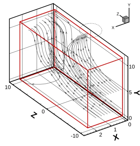
In the last group on Table 3 appears a result never observed until now, we can see in Figure 25 the return flow coming from the area downstream in the vicinity of Y/D = 0 and coming out near Y/D = 10.
0
5
10
Y
0
1
2
X
-10
0
10
Z
Z X Yd
Figure 25. Engine Trent 500 for U
i/U
∞=9.9 and H/Di=0.97
In the YZ plane we can see a small vortex in the downstream of the nozzle (Figure 26).
Z/D
Y/
D
-3 -2 -1 0 1 2 3 0 1 2 3Figure 26. Engine Trent 500 for U
i/U
∞=9.9 and H/Di=0.97,
X=0.5XTOT
Engine XZ YZ 3D Nº of vortex Vi/V∞ H/Di
cf6‐50 0 4.95 0.97 cf6‐6 0 4.95 0.97 cf6‐80a X(2) X 3 4.95 0.97 cf6‐80c2 0 4.95 0.97 cf6‐8oe1 0 4.95 0.97 cfm56‐2 0 4.95 0.97 cfm56‐3 0 4.95 0.97 cfm56‐5a 0 4.95 0.97 cfm56‐5b 0 4.95 0.97 cfm56‐5c 0 4.95 0.97 cfm56‐7 0 4.95 0.97 rb211‐535e4 0 4.95 0.97 trent 500 0 4.95 0.97 trent 700 0 4.95 0.97 trent 800 0 4.95 0.97 trent 1000 0 4.95 0.97 GE nx 0 4.95 0.97
Table 4. Summary of results for the selected conditions.
In table 4 we can verify the almost no vortex results with the only exception being the case the Cf6 80a engine, and his behavior is the same as described for the CF6-6 engine for the conditions in Table 3.
Engine XZ YZ 3D Nº of vortex Vi/V∞ H/Di cf6‐50 0 9.9 1.2 cf6‐6 0 9.9 1.2 cf6‐80a 0 9.9 1.2 cf6‐80c2 X(2) X 3 9.9 1.2 cf6‐8oe1 X X X 3 9.9 1.2 cfm56‐2 X 1 9.9 1.2 cfm56‐3 0 9.9 1.2 cfm56‐5a X 1 9.9 1.2 cfm56‐5b X 1 9.9 1.2 cfm56‐5c X 1 9.9 1.2 cfm56‐7 0 9.9 1.2 rb211‐535e4 X 1 9.9 1.2 trent 500 X X 2 9.9 1.2 trent 700 0 9.9 1.2 trent 800 X 1 9.9 1.2 trent 1000 X 1 9.9 1.2 GE nx X 1 9.9 1.2
Table 5. Summary of results for the selected conditions.
Regarding the results of Table 5 we can check the increasing of vortical structures mentioned before and the decrease of ground vortex. In Table 5 we can see five relevant result sets, two vortex in the XZ plane and one in the YZ plane. A vortex in the XZ plane one in the YZ plane and one in 3D. A 3D one. One 3D and one in the YZ plane and finally one in the YZ plane.
For the first situation we have the CF6-80C2 engine with two vortex in XZ and one in YZ. In the YZ plane emerges a structure similar to that described in Figures 13 and 14, and in relation to the XZ plane again there are two structures that look similar to those in Figure 19.
In the second situation three structures are visible in XZ and YZ and another one in 3D. In XZ a vortex arises in the area downstream of the stream as it is clearly visible in Figure 27.
Z/D
X/
D
-3 -2 -1 0 1 2 3 0 0.2 0.4 0.6 0.8Figure 27. Engine Cf6-80c2 for U
i/U
∞=9.9 and H/Di=1.2,
Y=0.5YTOT
In the YZ plane appears a weak vortex and an area where the flow enters a plane coming from behind the plane of the face of the engine and follows in main the flow direction (Figure 28).
Z/D
Y/
D
-3 -2 -1 0 1 2 3 0 1 2 3Figure 28. Engine Cf6-80c2 for U
i/U
∞=9.9 and H/Di=1.2,
X=0.5XTOT
The 3D structure is identical to one already mentioned above in relation to Figure 25.
In the third set only arise visible structures in 3D perspective, which may be of three types. One already referenced above (Figure 15). A flow in the same area but weaker (Fig. 29) and a third is already well defined vortex and strong influence on the flow (Figure 30).
0 5 10
Y
0 1 2X
-10 0 10Z
Z X Yd
Figure 29. Engine Cf56-2 for U
i/U
∞=9.9 and H/Di=1.2
0 5 10
Y
0 1 2X
-10 0 10Z
Z X Yd
Figure 30. Engine Cf56-5c for U
i/U
∞=9.9 and H/Di=1.2
The fourth set of results is the Trent 500 where the structures are of the same kind found in Figure 25 and Figure 26.
Finally the fifth set of results which has only one YZ vortex, which is similar to others previously mentioned in terms of position but of greater intensity (Figure 31).
Z/D
Y/
D
-3 -2 -1 0 1 2 3 0 1 2 3Figure 31. Engine Trent 800 for U
i/U
∞=9.9 and H/Di=1.2,
X=0.5XTOT
Figure 32 shows three-dimensional particle tracks for the Trent 900 and the GE nx engines for velocity ratios between the inlet and the crossflow, Ui/U∞, of 4.95, 9.8 and 19.8.
The vortex structure is detected for both engines for the highest velocity ratio (Fig. 32 e and f) with fluid being captured from both sides of the engine inlet that form a spiral directed towards the engine inlet.
For an intermediate velocity ratio of 9.9 the intake fluid is also being sucked upstream and
downstream of the engine inlet but the spiral tendency is only noticeable for the case of the GE nx engine.
For the smallest velocity ratio (Ui/U∞ =4.95) the crossflow is less deflected by the engine for the
Trent 900 case, while in the case of the GE nx is deviated towards the vertical plane of symmetry to form an outwards jet-like flow (in the opposite direction of the engine inlet flow).
Figure 32. Three-dimensional particle tracks. Trent 900 GE nx-1B64 Ui / U ∞ = 4. 95 0 5 10 Y 0 1 2 X -10 0 10 Z Z X Y
a
0 5 10 Y 0 1 2 X -10 0 10 Z Z X Yb
Ui / U ∞ = 9. 9 0 5 10 Y 0 1 2 X -10 0 10 Z Z X Yc
0 5 10 Y 0 1 2 X -10 0 10 Z Z Yd
X Ui / U ∞ = 1 9.8 0 5 10 Y 0 1 2 X -10 0 10 Z Z X Ye
0 5 10 Y 0 1 2 X -10 0 10 Z Z Yf
X 22The flow pattern described before is associated with typical ground pressure distributions that are shown in Fig. 33.
The static ground pressure nondimensionalized by the crossflow kinematic energy ( ) is
shown for the same conditions of Fig. 32 and both the Trent 900 and the GE nx-1B64 engines.
2 U 2 / 1
For the smallest velocity ratio (Fig. 33a and b) the negative pressure region is about the same size with intensity(pp)/(1/2U2)1.0.
For a velocity ratio, Ui/U∞, of 9.9 (Fig. 33c and d), the negative region in the upstream side of the
inlet becomes more intense with values of (pp)/(1/2U2 ) near -2.5, but in the downstream side the slight positive region also increases.
Finally, for the highest velocity ratio of Ui/U∞=19.8 (Fig. 5e and 5f)most of the ground floor is
subjected to a relevant positive pressure,0.25(pp)/(1/2U2)0.5, but a high suction region(pp)/(1/2U2)2.5 in the inlet direction occurs.
The negative region is located in the upstream side for the Trent 900 case and its extension is about ¾ of the inlet diameter while for the case of the GE nx is considerably larger with a size slightly larger than one inlet diameter.
In spite of these negative values a small high pressure region can be observed in the downstream side which is associated with the tendency for the formation of a stagnation line and the
Figure 33. Ground pressure distribution(pp)/(1/2U2).
a
Trent 9 00 Z/D Y/ D -3 -2 -1 0 1 2 3 1 2 3 P 0.25 0 -0.5 -1 -1.5 -2 -2.5b
Ui / U ∞ = 4.95 GE n x-1B6 4 Z/D Y/ D -3 -2 -1 0 1 2 3 1 2 3 P 0.25 0 -0.5 -1 -1.5 -2 -2.5c
Trent 9 00 Z/D Y/ D -3 -2 -1 0 1 2 3 1 2 3 P 0.25 0 -0.5 -1 -1.5 -2 -2.5d
Ui / U ∞ = 9. 9 GE n x-1B6 4 Z/D Y/ D -3 -2 -1 0 1 2 3 1 2 3 P 0.25 0 -0.5 -1 -1.5 -2 -2.5e
Trent 9 00 Z/D Y/ D -3 -2 -1 0 1 2 3 1 2 3 P 0.25 0 -0.5 -1 -1.5 -2 -2.5f
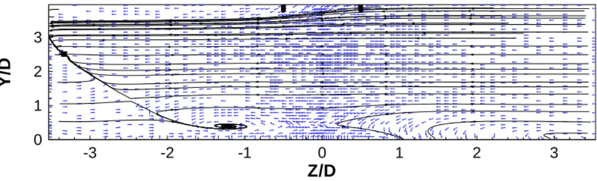
Ui / U ∞ = 19.8 GE n x-1B6 4 Z/D Y/ D -3 -2 -1 0 1 2 3 1 2 3 P 0.25 0 -0.5 -1 -1.5 -2 -2.5 24The formation of the ground vortex near the wall is further analyzed with the help of Fig. 34 which shows near wall velocity vectors and particle streaks for the GE nx-1B64 case.
The upstream and downstream flow converge to a line for the smallest and highest velocity ratio
(Fig. 6a and c), while for Ui/U∞=9.9 (Fig. 34b) converge to a stagnation saddle point indicating the
presence of the inlet vortex formation.
The main difference between the first and the third cases is the length of the diverted flow in the Y direction (horizontal parallel to the axis of the engine inlet) which increases from less than 1D to about twice with the velocity ratio.
Figure 34. Near wall velocity vectors and particle streaks for GE nx-1B64 test case.
a Ui / U ∞ = 4. 95 Z/D Y/ D -3 -2 -1 0 1 2 3 0 1 2 3 b Ui / U ∞ = 9. 9 Z/D Y/ D -3 -2 -1 0 1 2 3 0 1 2 3 c Ui / U ∞ = 1 9.8 Z/D Y/ D -3 -2 -1 0 1 2 3 0 1 2 3
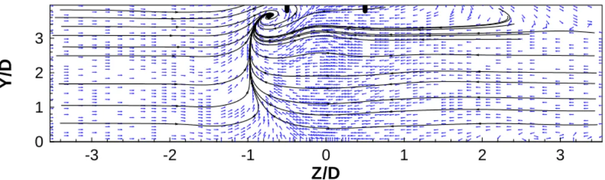
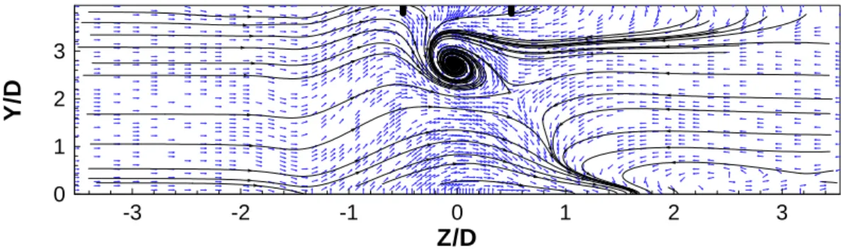
For the intermediate velocity ratio Ui/U∞=9.9, Fig.35 shows the details of the flow pattern near
the wall for the Trent 900 and the GE nx engines.
The stagnation point was detected for both engines but the misalignment with the crossflow is more pronounced for the GE nx.
For this velocity ratio the flow pattern is completely different from the observed for the lowest and highest velocity ratios with the flow converging to a single point at about 0.5D from the inlet plane.
It should be pointed out that from the three-dimensional perspectives of the flow (Fig. 32c and d) it is not possible to identify clearly any vertical structure that can be detected from this kind of near wall flow patterns.
Figure 35. Detail of the near wall velocity vectors and particle streaks for Ui/U∞=9.9.
Trent 90 0 Z/D Y/ D -1 0 1 2 2.5 3 3.5 GE nx-1B64 Z/D Y/ D -1 0 1 2 2.5 3 3.5 26
Figure 36 shows the typical flow development at the vertical plane near the engine inlet which assumes a similar pattern for all the test cases. The air is sucked in all directions towards the center of the inlet in a slightly distorted radial direction.
Z/D X/ D -3 -2 -1 0 1 2 3 0 0.2 0.4 0.6 0.8
Figure 36. Typical Flow pattern at the vertical plane near the engine inlet for all the test cases (present results for Trent 900, Uin/U∞=19.8 and h/Di=0.97, vertical plane parallel to the
engine inlet at 56mm of distance).
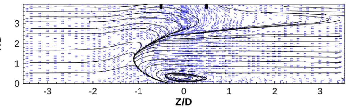
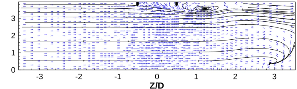
Away from the engine inlet at a distance of Y=5.6m measured along the axis, the flow is considerably different for each engine and test case (Fig. 37).
The core of a spiral can be identified for both the Trent 900 and the GE nx-1B64 engines, but its center is closer to the ground in the former case. It should be pointed out also that the cross-section of the flow is considerably larger for the case of the GE nx-1B64.
For the Trent 700 engine the vortex flow exists near the ground at the same plane but with an opposite sign (clockwise).
With a smaller velocity ratio (Ui / U∞ = 9.9) the vortex flow becomes weaker (Fig. 37) and for the
a T rent 90 0 Z/D 0 X/ D 0.2 0.4 0.6 -3 -2 -1 0 1 2 3 0.8 b GE n x -1B64 Z/D 0 X/ D 0.2 0.4 0.6 -3 -2 -1 0 1 2 3 0.8 c T rent 70 0 0 X/ D 0.2 0.4 0.6 Z/D -3 -2 -1 0 1 2 3
Figure 37. Velocity vectors and particle tracks in a vertical plane parallel to the engine inlet
at 5.6m of distance (U
i/ U
∞= 19.8).
a Trent 900 Z/D X/ D -3 -2 -1 0 1 2 3 0 0.2 0.4 0.6 0.8 b GE nx-1B64 Z/D X/ D -3 -2 -1 0 1 2 3 0 0.2 0.4 0.6 0.8 c Trent 700 Z/D 0 X/ D 0.2 0.4 0.6 I t t
n these cases the crossflow is only slightly distorted but in general keeps its initial direction. For he Trent 900 and GE nx-1B64 the vortex flow can be already identified at 5.6m of distance from he inlet (Figs. 38a and b).
-3 -2 -1 0 1 2 3 d Cf6-80a 0 X/ D 0.2 0.4 0.6 Z/D -3 -2 -1 0 1 2 3
Figure 38. Velocity vectors and particle tracks in a vertical plane parallel to the
X/D Y/ D 0 0.25 0.5 0.75 0 1 2 3
Figure 39. Velocity vectors and particle tracks in a vertical plane parallel to the engine axis at
Z=0.57Di
The existence of the trailing vortex was also investigated for all the test cases since it should be present all of the engine/test cases. Nevertheless, it was only clearly identified for some engine and more study is still needed.
Chapter 4
Conclusions
The present study has shown that the inlet flow of a gas turbine engine is strongly dependent on the velocity ratio between the inlet and any crosswind as well as on the diameter at its position above the ground.
Different engines have been studied and the formation of vortex was identified for all engines. The affected flow region was found to be considerably different in size. The trailing vortex could be clearly noticed for some engines.
Away from the inlet plane other types of complex vortical structures were identified that have different signs depending on the clearance distance of each particular engine and initial conditions.
By analyzing the different tables we can see the influence of inlet velocity and H in vortical structures.
We can conclude that for high inlet velocities vortical structures are almost exclusive to the XZ plane and with its decrease the formation of vortex passes through two stages one intermediate of an increase in vorticity at all levels and the second for low inlet velocities of almost absence of vortex.
With increased ground clearance to the shaft of the engines we see a change in the type of vortex that arise, with a decrease of it in the XZ plane, roughly the same number of structures in the YZ plane and big structures that are only possible to visualize in 3D perspective.
References
1Hünecke, K. “Jet Engines: Fundamental of theory, design and operation”, Airlife publishing, UK,
1997.
2Mattingly, J.D., Heiser, W.H., Daley, D.H. “Aircraft Engine Design”, AIAA Education Series, New
York, 1987.
3Mattingly, J.D. “Elements of Gas Turbine Propulsion”, Singapore: McGraw-Hill, 1996.
4Johns, C. “The Aircraft Engine Inlet Vortex Problem”, AIAA’s Aircraft Technology, Integrations
and Operations (ATIO) 2002 Technical, 1-3rd 2002, Los Angles, California, AIAA Paper 2002-5894.
5Swainston, M. “Vortex Formation Near Intakes to Turbomachinery and Duct Systems”, Heat and
Fluid Flow, Vol. 4, No. 2, 1974.
6Nakayama, A. & Jones, J. “Correlation for Formation of Inlet Formation”, AIAA Journal, Vol. 37,
No. 4: Technical Notes, 1998.
7Motycka, D. & Walter, W. “An Experimental Investigation of Ground Vortex Formation During
Reverse Thrust Operation”, AIAA Paper No. 75/1322, AIAA/SAE 11th Propulsion Conference, 1975
8Brix, S., Neuwerth, G. & Jacob, D. “The Inlet-Vortex System of Jet Engines Operating Near the
Ground”, AIAA Paper 2000-3998, 2000
9De Siervi, F., Viguier, H., Greitzer, E. & Tan, C. “Mechanisms of Inlet Vortex Formation”, J. Fluid
Mech., Vol. 124, pp. 173-207, 1982
10 Nakayama, A. & Jones, J. “Correlation for Formation of Inlet Formation”, AIAA Journal, Vol. 37,
No. 4: Technical Notes, 1998.
11Barata, J. M. M., Maneta, A.M., Silva, A.R.R. “ Numerical Study of Single Impinging Jets Through
a Crossflow”, AIAA Paper no. 2009-4801, 45th AIAA/ASME/SAE/ASEE Joint propulsion Conference &
Exhibit, Denver, CO, 2-5 Aug., 2009.
12Leonard, B. P. “A Stable and Accurate Convective Modelling Procedure Based on Quadratic
Upstream Interpolation”, Computer Methods in Applied Mechanics and Engineering, Vol. 19, No.1, pp. 59-98, 1979
12Patankar, S. V. and Spalding, D. B. "A Calculation Procedure for Heat, Mass and Momentum
Transfer in Three- Dimensional Parabolic Flows", International Journal of Heat and Mass Transfer, Vol. 15, No. 10, pp. 1787-1805, 1972.