Advances in Mechanical Engineering 2015, Vol. 7(5) 1–16
ÓThe Author(s) 2015 DOI: 10.1177/1687814015585486 aime.sagepub.com
Research on safety analysis for
airborne system based on extended
functional model
Quan Jiang
1,2, Chunling Zhu
1, Dejian Cao
1, Chuanlin Huang
1and Jian Xie
1Abstract
With the widespread use of embedded system in safety critical areas, system safety assurance has become one of the research hotspots of engineering technologies. System safety analysis mainly concentrates on the requirement specifica-tion and the recent design, and in the process of the actual development of the software, safety requirement analysis and design are two independent processes. This article expands the safety requirements described by fault tree into state diagram and proposes the new concept ‘‘fault state diagram,’’ which can unify safety requirement model and functional model. Based on the fault state diagram, this article proposes the method of airborne system safety analysis, including the following: gives out one method for abstracting and describing safety requirements from system fault tree based on Backus Normal Form; defines the transformation rules from fault tree logic gates and continuous time into state diagram elements; designs safety requirement information mapping table which translates safety requirements into state diagram elements; and designs the automatic construction algorithm of fault state diagram, which is based on the transformation rules and mapping table. Finally, a small gas stove control system case using the method proves the feasibility and effec-tiveness of the proposed method.
Keywords
Airborne system, fault tree, state diagram, safety requirement
Date received: 10 February 2015; accepted: 8 April 2015
Academic Editor: Hamid Reza Shaker
Introduction
Safety refers to the lack of a state or a situation that can cause an accident, which is an unexpected occur-rence of ‘‘death, injury, illness, damage to or loss of property, or environmental harm’’.1–3With wide use of the embedded system in the safety critical areas, such as medical science, transportation, and aerospace, soft-ware has become a key factor in determining the safety of the system. System failure may not only cause harm to environment and property loss but also lead to casu-alties.4In recent years, the accidents caused by software failure happen frequently.5 For example, in 2009, Turkey Airlines Boeing aircraft crashed in the Atlantic because of having no program to deal with the stall
situation.6 In the same year, A330-200 aircraft of Air France crashed because of ignoring to set the limitation of height value in software.7It has become an impor-tant research topic for industrial and academic circles to improve software safety to prevent catastrophic accidents.
1Nanjing University of Aeronautics and Astronautics, Nanjing, China 2China Academy of Electronics and Information Technology Beijing,
China
Corresponding author:
Chuanlin Huang, Nanjing University of Aeronautics and Astronautics, Nanjing 210016, China.
Email: [email protected]
Safety analysis mainly concentrates on the require-ment specification and design at present. Leveson1 pointed out that errors of requirement specification and the short-sighted design are the most important factors which influence system safety. Overall, the cur-rent safety analysis method can be divided into two categories: one is the safety requirement quantitative or qualitative analysis based on fault tree (FT) model which can analyze the existing harm of a system, the probability of happening of the harm, and the quanti-tative or qualiquanti-tative analysis of the system; the other ensures that the safety requirements are met in system design through building system function model in the development process and using safety analysis methods and verification tools which are well-known in the industry for verification and analysis. However, in the actual process of development, safety requirement anal-ysis and design are two relatively independent pro-cesses. The safety requirement analysis process and design process caused by it do not match each other well. On one aspect, the result of safety requirement analysis is difficult to embody in the design directly and guide the building and modification of the design model. On the other aspect, safety analysis is difficult to be done in the design process, which makes design model difficult to analyze the system safety.
Fault tree analysis (FTA),8 which is a traditional technology tool for safety analysis, plays an important role in the embedded system engineering. It concerns the relationship between system fault and the cause of the fault. However, it cannot determine whether such problem exists in system design. State diagram (SD)9–11 can effectively describe transformation of system func-tion and states. However, the potential design fault of the system is difficult to be found because of the lack of visual expression of the safety requirements. Therefore, on the basis of the features of FT and SD, this article proposes the concept of fault state diagram (FSD) and gives one system safety analysis method based on FSD.
The other sections are as follows: section ‘‘System safety analysis method based on FSD’’ introduces the FT and SD briefly and gives the concept of FSD and the safety framework based on FSD. Section ‘‘Building of the FSD’’ gives the method of extracting and describ-ing safety requirement information from FT based on Backus Normal Form (BNF), defines the transforma-tion rules from FT logic gates and continuous time into SD elements, and designs the safety requirement infor-mation mapping table from safety requirements to ele-ments; finally, it designs the automatic building FSD algorithm based on safety requirement information table and transformation rules. Section ‘‘Case study’’ describes using the method to analyze a small gas stove control system case. Section ‘‘Related work’’ introduces the related work. Section ‘‘Conclusion’’ is the summary of this article.
System safety analysis method based on
FSD
FT
FT analysis is one of the most representative methods in safety analysis, which was first proposed by USA Baer Telegraph Company in the 1960s. FT is rapidly applied to safety critical areas, such as the nuclear industry, deep space exploration, electronics, and machinery, because of its intuitive, easy to understand, rigorous logic, flexibility, and other advantages. FT uses the top event to describe the special problems of system. FT uses the basic events, intermediate event, and logic gates to express the fault and the causal rela-tionship among the causes of the fault. Through the quantitative or qualitative analysis of the top event, engineers can judge whether the system design meets the safety requirements. By finding the potential design defects of the system, engineers can take the corre-sponding measures to guide the software design and implementation. It is an important analysis method to ensure system safety.
Events and logical gates are the basic structural unit of FT. Events can be classified as top event, inter-mediate event, and basic event. Logic gates are used to express the relationship among the fault factors. The common logic gates are AND gate, OR gate, Priority AND gate, NO gate, Voting gate, and Except gate. These logic gates can make analysts to construct a rela-tionship among the FT and components and locate the fault position. The analysis of the FT includes qualitative analysis12,13 and quantitative analysis14,15 and determination of the minimum cut sets of the FT is one of the most important methods of it. Cut set is the set of basic events which can make the top event happen. Qualitative analysis is used to find the cause of all possible failure modes of the top events, and quantitative analysis is used to calculate the probability of the top event according to the basic events probability.
SD
SD is one of the important models for system behavior in United Modeling Language (UML), which can be used to describe the state, event leading to the state transforming, and relative activities of the object in the life cycle. SD can describe the orders of the transforma-tion state and the relative events, activity, guard, and so on. SD is one of the common and important system design models for the software safety analysis.
relationship among the system functional model and components and also is the most commonly used method in the industrial and academic circles. These methods based on the theory of automata or Petri net can transform the special SD into formal models, such as timed automata, extended hierarchical automata, and colored Petri net. Then, these methods are used to verify the transformed models, through which can find the system error or guide the generation of test case. The common analysis processes are as follows: first, defining the transformation rules between SD elements and timed automata or other formal modeling lan-guage; second, according to the rules, transforming the SD formally; third, appropriating the transformed model; fourth, extracting the safety requirement verifi-cation specifiverifi-cation from design document or safety requirement analysis model; fifth, using the model checker to verify whether the model meets the safety requirement specification; sixth, according to the result, analyzing the system design model.
FSD
According to the introduction of FT analysis and SD analysis, we find some flaws. First, FTA mainly con-cerns about the problems of system faults and the cause of the fault happening, as well as the relation-ship among the faults, but it does not give the link among the reasons causing the system fault and the specific behaviors. It is difficult to confirm the exis-tence of such a fault in the system. Second, SD can describe the behavior and state transformation effec-tively. Because of the lack of intuitive description of system faults, the potential behavior or behavior composition which leads to failures is difficult to be found. However, in the system safety analysis work, analysis and verification personnel have knowledge not only of the function model but also of the fault model. Therefore, the system behavior model includ-ing the fault information is very important in the sys-tem safety analysis. According to the fault extension of SD, this article unifies the functional model and safety requirement model of the system and proposes the concept of fault-extended SD:
Concept 1: FSD—one SD, which can describe the system function and safety requirements, extended the fault information into the relative system beha-vior and components;
Concept 2: fault State—the special state describing the fault problems reflected by the top event of the system FT in the FSD;
Concept 3: fault region—the sets of state, transfer, and components among fault problems and the rela-tionship of the cause of the fault in the FSD.
Concept 4: function region—the sets of state, trans-fer, and components which describe the system func-tion in the FSD.
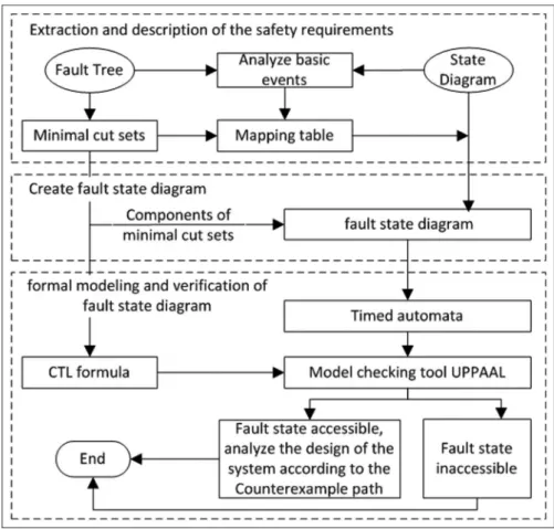
The FSD can describe the function of the system and the safety requirements of the system simultane-ously. Combining with model checking technology, this article proposes a method of safety analysis based on FSD for the analysis work at the stage of design. The detail processes can be seen in Figure 1. This method includes three steps: first, extracting the safety requirements from the FT, checking out the basic events and minimum cut sets, and filling the safety requirement mapping table; second, according to the mapping table and the transformation rules between logic gates and sate diagram elements, using the safety requirements to extend the system SD; third, to con-struct system FSD transforming the FSD into formal model and using the model checker to verify it. In order to reduce complexity, the FT used in this article only contains basic event, intermediate event, and top event; logic gate contains OR gate, AND gate, and Priority AND gate. The future work will study the other events and logic gates.
Building of the FSD
This section details the method of extracting and describing the safety requirements including basic event, the minimum cut sets, and top event and then defines the mapping table from safety requirements to SD elements and the transformation rules from FT logic gates into SD elements; finally, it designs the algo-rithm of automatically constructing FSD and the safety requirement information mapping table.
Extracting and describing the safety requirement
information
We use the combination of the inputting events of the logic gate to replace the outputting event of the logic gate until the top event is replaced by the basic events. Finally, we can get a Boolean expression consisting of logic operators and basic events. We use the BNF to describe the Boolean expression which is on behalf of the safety requirements. As shown in Table 1, TopEvent is the top event of the FT, Gate is the logic gate, Gate-Inputs is the inputting of the logic gate, basic-event is the basic event, and operand is the logic operator.
system behavior model. As is shown in Table 2, the BNF describes top event by the minimum cut set.
The safety requirements described by the FT not only contain top event, intermediate event, and basic event but also contain the relationship among them. In order to assure the accuracy of the description, we should preserve the logic relationship among them, which is shown in Table 3.
As is shown in Table 4, some important equivalence properties are given. According to these properties, we can simplify the BNF expression of top event and mini-mum cut sets.
Because of the different functions of FT and SD, we should eliminate the difference. First, we should decom-pose the basic events and establish the corresponding relationship with the SD elements. This article
decomposes basic events into ‘‘atomic event’’ and ‘‘composite event,’’ whose definitions are as follows:
Definition 1: atomic event—the basic event or the decomposition of the basic event of FT which is consistent with the SD element;
Definition 2: composite event—the event that can be decomposed into many basic events of FT.
Figure 1. Safety analysis framework of software based on FSD.
Table 1. BNF of the top event.
\TopEvent.::=\Gate.
\Gate.::= (\operand.,\Gate-Input.)
\Gate-Input.::=\basic-event.,\basic-event.j \basic-event.,\Gate.j\basic-event.,\Gate-Inputs.j \Gate.,\Gate-Inputs.
\operand.::=^j_j^j
Table 2. BNF of the top event using the minimum cut set.
\TopEvent.::=\CutSet.j(\operand.,\CutSets.) \CutSets.::=\CutSet.,\CutSet.j\CutSet., \CutSets.
\operand.::=_
Table 3. BNF of minimum cut set.
\CutSet.::=\basic-event.j(\operand.,\basic-events.) \basic-events.::=\basic-event.,\basic-event.j\ basic-event.,\basic-events.
The relationship between basic event, atomic event, and composite event described by BNF is shown in Figure 6. Atomic events are independent from each other and correspond with specific elements which are different from each other in the SD. When a basic event is the composite event, we should decompose it. Logic relationship among the atomic events decomposed from composite event is ‘‘and.’’ Other type shown in Table 5 is the element which is not referred.
Safety requirement information mapping table
In order to make the automatic extension for translat-ing the safety requirement information into SD, we should make the relationship between safety require-ment information and SD elerequire-ments with consistent clear semantic description. The mapping relationship between safety requirement information and SD ele-ments is shown in Table 6.
The mapping table must be filled by the analysis per-sonnel manually after extracting the safety requirement information. In order to facilitate more rationally, the process of filling the table should follow the order below: first, filling the basic events; second, filling the decomposed events of composite events and minimum cut sets; finally, filling the top events. All properties required to be filled in the table are shown in Table 1.
1. Id: the unique identities of the safety require-ment information in the mapping table, which begins with Event whose suffix is a number digi-tal such as Event1 and Event2;
2. Name: name of the safety requirement
information;
3. Type: all safety requirement information is divided into five categories as given below:
Detectable: this safety requirement informa-tion is a basic event or Composite Event which can be linked with one or more ele-ments in SD.
Injectable: this safety requirement informa-tion cannot be linked with one or more ele-ments of SD, but can be expressed by adding a component into the system.
CutSet: this safety requirement information is minimum cut set.
Time: this safety requirement information can be linked with the relative elements of SD and is limited by time.
TopEvent: this safety requirement informa-tion is top event.
4. Complexity: it can be subdivided into the fol-lowing two categories:
Atomic: this safety requirement information is atomic event and is also Detectable. Composite: this safety requirement informa-tion is composite event and is also Detectable.
5. Element: the type of the elements linked with the safety requirement information, including Variable, State, Event, and Transition;
6. Component: the name of the component of the SD linked with FT;
7. Argument: this content depends on the proper-ties of Type and Complexity, which are described in Table 7.
Table 4. BNF of important equivalence properties among operators.
\^, A, B.=\^, B, A. \^, A, A.= A \_, A, B.=\_, B, A. \_, B, B.= B
\^, A,\^, B, C..=\^, A, B, C. \_, A,\_, B, C..=\_, A, B, C. \^, A,\^, B, C..=\^, A, B, C.
\^, A,\_, B, C..=\_,\^, A, B.,\^, A, C.. \_, A,\^, B, C..=\^,\_, A, B.,\_, A, C.. \^, A,\_, B, C..=\_,\^, A, B.,\^, A, C..
Table 5. BNF of basic events.
\basic-event.::=\atomic-event.j\composite-event. \composite-event.::= (operand,\atomic-event.,\
atomic-event.j\composite-event.,\atomic-event.)
\atomic-event.::=statejeventjtransitionjactionjactivity
j
threshold of some durationjother \operand.::=^
Table 6. Safety requirement information mapping table.
Name Options
Id –
Name –
Type Detectable, Injectable, CutSet, Time, TopEvent Complexity None, Atomic, Composite
Element None, Variable, State, Event, Transition Component None or the name of relative component
of the SD Argument –
Transformation rules
AND gate is one of the most common types of logic gates in the FT and is expressed by the symbol ^, which means that outputting event will happen only if all the inputting events happen. AND gate can also be expressed by the inputting region and logic region of SD. Inputting region is used to represent the inputting of AND gate. Logic region is used to represent the logic relationship which reflects the interaction between the inputting events. As is shown in Figure 2, Incr is the incremental event, which represents the variable self-increment; Decr is the decrement event, which rep-resents the variable self-reduction.17
Transforming the AND gate in this way can fully manifest the semantic characteristics of the AND gate. When the number of the inputting events increases, we just need to split the inputting region again. But when the number of inputting events of the AND gate becomes too large, this way will produce a large num-ber of intermediate states, which creates difficulties in the analysis of the follow-up work. In order to mini-mize the intermediate state, we can achieve it by coun-ter. Counter consists of two state counters, two pseudo state C, variable count, incremental Incr, decrement Decr, and six transfers, which are shown in Figure 3. Counter’s initial status is Counter. When the incremen-tal event occurs, it triggers incremenincremen-tal transfer, and count variable becomes count + 1. Then, it enters the state of pseudo C and determines whether the count variable is equal to the threshold limitation value n. If the result is true, exit from the Counter or return to the state counter. When the decrement event Decr occurs, it triggers decremental transfer and counter becomes count21, and it enters the state of pseudo state C. Check whether the variable count is 0. If the result is true, exit from the Counter or return to the state counter.
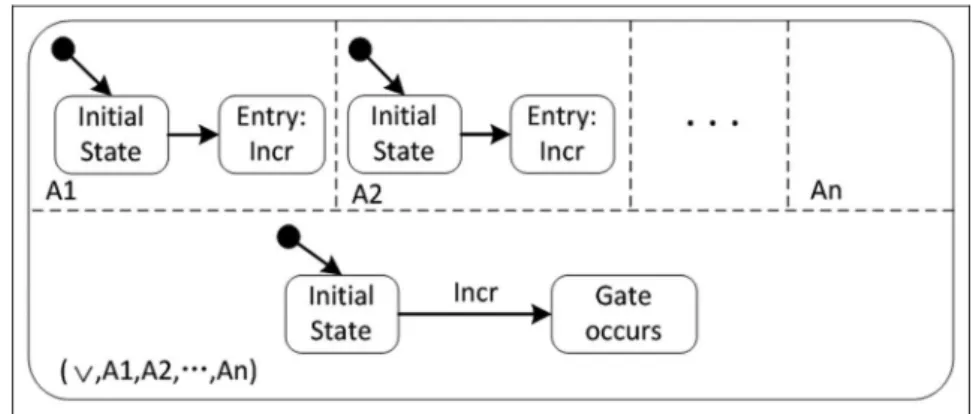
If the state counter exists, we should not add the intermediate state unlimited when the number of input-ting events is large. Figure 4 shows the SD of AND gate with n inputting events.
OR gate is expressed by the symbol _. Similar to AND gate, OR gate can also use two orthogonal state
regions: inputting region and logical region. As is shown in Figure 5, as long as there is an inputting event occurring, the top event will occur. As a result, we only need to add one corresponding component linked with the inputting event when the number of the inputting events increases.17
Priority AND gate is expressed by the symbol ^. The only difference between Priority AND gate and AND gate is that the inputting events of the Priority gate occur in sequence. The only difference between the SD of Priority AND gate and AND gate is that we should give different tags to every entrance trigger events reached by linking inputting event and should be triggered in turn. As a result, we only can go on cutting the intermediate state of the inputting region and add-ing the intermediate state of the logic region. Figure 6 shows the transformation of the Priority AND gate.17
In system FT, some special basic events associated with time may exist which are limited by time. SD is
Table 7. Classification combination of fault information.
Type Complexity Argument
Detectable Atomic The element of SD corresponding to safety requirement information
Detectable Composite Expression combined with Id of safety requirement information and logic operator Injectable None Transfer from initial state into fault state
CutSet None Expression combined with Id of safety requirement information and logic operator
Time None Time valve value
TopEvent None Expression combined with Id of safety requirement information and logic operator
SD: state diagram.
Figure 2. Transformation of AND gate.
real-time synchronization language, which is suitable for the modeling of the complex real-time embedded system. In the SD, the response time of the state is gen-erally negligible. In this article, we use the boundary condition and timeout event to realize the transforma-tion of the SD of continuous time.10,16As is shown in Figure 7, when time is over the border time ‘‘bound,’’ it will trigger timeout event and the system will transfer from the initial state into the goal state.
Figure 4. Representation of AND gate with n inputting events.
Figure 5. OR gate representation.
Figure 6. Priority AND gate transformation.
Building the FSD
FT mainly consists of the fault region and the function region. The fault region is used to describe safety requirements coming from the expansion of the safety requirements. The function region is used to describe system function coming from system SD. Therefore, the construction of the FSD is the construction of the fault region and the fixing of the function region. The construction of the fault region is based on SD and converts the safety requirements into SD symbols which are added to system SD. In the process, every system SD element is not static. The fixing of the func-tion region is to add relative acfunc-tion, transfer, and event to the linked elements of the system diagram basic event. The SD elements added to the function region only work in the fault region and have no effect on the system function. The algorithm is as follows:
1. Fill the information list MapTableList with all safety requirement information of the mapping table.
2. If the MapTableList is not null, cyclically read the records and then judge its property. If Type = Detectable and Complexity = Atomic, then go to step 3; if Type = Detectable and Complexity = Composite, then go to step 4; if Type = Injectable, then go to step 5; if Type = Time, then go to step 6; if Type = CutSet, then go to step 7; if type = TopEvent, then go to step 9.
3. If Element = Transition or Event, add an incre-ment action to corresponding transfer or event and name it after Name + ’.Incr’. If Element = State, add new entry action for the correspond-ing state and name it after Name + ’.Incr’; if the transfer which can trigger the state exists, then add export action and name it after
Name + ’.Dncr’, as well as add Id to
HasOpposingElementList; finally, move the safety requirements out of the MapTableList. 4. Read all the operands of the expression of
Argument and do the following operations for each operand: according to the operand, find the corresponding safety requirements informa-tion F in MapTableList. If F.Element = Transition or Event, add an increment action to the corresponding transfer or event and name it after Id + ’.Incr’; if F.Element = State, then add new entry action to corresponding state and name it after Name + ’.Incr’; if the transfer which can trigger the state exists, then adding export action, name it after Id + ’Dncr’, as well as set the value of the Opposite to 1; if F.Type = Time, then fix the state according to the transformation rules in section ‘‘Safety
requirements information mapping table’’ and add transfer TimeOut for the state and incremen-tal action and name it after Id + ’.Incr’; if the transfer which can trigger the state exists, then add decrement action to the corresponding state and name it after Id + ’Dncr’ as well as set the value of the Opposite to 1 and move the safety requirements out of the MapTableList. Build new component according to section ‘‘Safety requirements information mapping table,’’ and the new component is named after Id. Initial state is named after No_ + Name. Fault state is named after the value of Name. The entry action of fault state is named after Name + ’.Incr’. If Opposite = 1, then add export action for the fault state, which is named after Name + ’.Decr’ as well as add Id in HasOpposingElementList; move the safety requirements information out of the MapTableList.
5. Build new component named after Id, and the fault state is named after the value of the Name; the transfer from initial state into fault state is the value of Argument. The entry action is named after Name + ’.Incr’. Move the safety require-ment information out of the MapTableList. 6. Fix the state according to the transformation
rules in section ‘‘Safety requirements information mapping table’’ and add TimeOut event and incremental action Name + ’.Incr’ to the state; if the transfer which can trigger the state exists, then add decrement action Name + ’.Decr’ as well as Id to HasOpposingElementList; move the safety requirement information out of the MapTableList.
7. In order to make the following convenient, set the safety requirement information as CutSet; set global variable Num to1 and read it into Argument expression as the parameters of step 8, then go step 8.
Num = Num + 1. Build logic region for the expression according to section ‘‘Safety require-ments information mapping table.’’ If this oper-ator is not the first operoper-ator of the expression in the CutSet.Argument, then logic region is named after CutSet.Name + ’_’ + which is the value of the expression; fault state is named after CutSet.Name + ’’_input’’ + Num; entry
action is named after Entry:CutSet.
Name + ’’_Input’’ + Num + ’’.Incr’’; export action is named after Entry:CutSet.Name + ’’_Input’’ + Num + ’’.Decr’’. Otherwise, both logic region and fault state are named after CutSet.Name. Fault state adds the entry action CutSet.Name + ’.Incr’. Move the safety
requirements information out of the
MapTableList.
9. Set the safety requirement information as TopEvent and build inputting region and logic region according to the transformation rules for Argument in section ‘‘Safety requirements
information mapping table.’’ Read expression from left to right until meeting operator and building to do the following operation for each operator: set current operator object as CutSet,
building new component named after
TopEvent_ + CutSet.Name. Fault state is named after CutSet.Name. Add entry action TopEvent + ’.Incr’ for the fault state. The transfer from initial state into fault state is CutSet.Name + ’.Incr’. Both logic region and fault state are named after TopEvent, and add entry action TopEvent.Name + ’.Incr’ for fault state. Finally, add a fault state for the system diagram named after TopEvent.Name; the transfer from component which can describe the function of the system to fault state is TopEvent.Name + ’.Incr’; move the safety requirement information out of MapTableList.
The code description of the algorithm execution is as follows:
public static void DrawStatecharts(FactorySafetyReq F){
List\SafetyReqInfo.MapTableList = new ArrayList\SafetyReqInfo.(); SafetyReqInfo s = null;
int [] flagGroup = null; int count;
MapTableList = F.getSafetyReqList(); flagGroup = new int[MapTableList.size()]; count = 0;
for (inti = 0; i\MapTableList.size(); i + + ){ if (flagGroup[i]) != 1){
s = MapTableList.getIndex(i); switch(s.getType()){
case Type.Detectable:
if(s.getComplexity().equals(‘‘Atomic’’)){
DrawAtomic(s, MapTableList, flagGroup, count); }else if(s.getComplexity().equals(‘‘Composite’’)){
DrawComposite(s, MapTableList, flagGroup, count); }
break;
case Type.Injectable:
DrawInjectable(s, MapTableList, flagGroup, count);break; case Type.Time:
DrawTime(s, MapTableList, flagGroup, count);break; case Type.CutSet:
DrawCutSet(s, MapTableList, flagGroup, count);break; case Type.TopEvent:
DrawTopEvent(s, MapTableList, flagGroup, count);break; }
}else{
continue; }
The algorithm above can complete the building of the FSD automatically. Steps 2–4 and 9 are the fixing of the function region. Steps 5–8 are the processes of building the fault region. Step 9 adds fault state to the function region, which means the top event of the FT. Therefore, if error happens, the function region will transfer into fault state.
Case study
This section studies one gas stove control system using this method, including extracting and describing safety requirements from FT, decomposing basic events, fill-ing the safety requirement information mappfill-ing table, and building the system FSD.
System overview
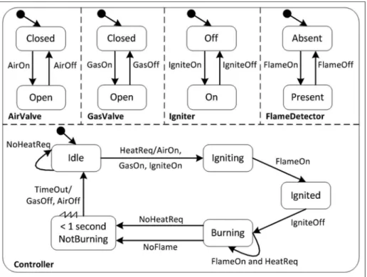
The gas stove control system has four main functions: the opening and closing of the gas and air valve, using a spark to ignite the gas, and determining whether the current gas is burning through flame detector. The requirements of the gas stove control system are as fol-lows: (1) gas concentration around the gas stove should always be less than the specified critical value; (2) when a request of heating arrives, it should be ensured that the gas stove can work normally and generate heat; and (3) when the heat request is ended, it should be guaranteed that the gas stove extinguishes the flame
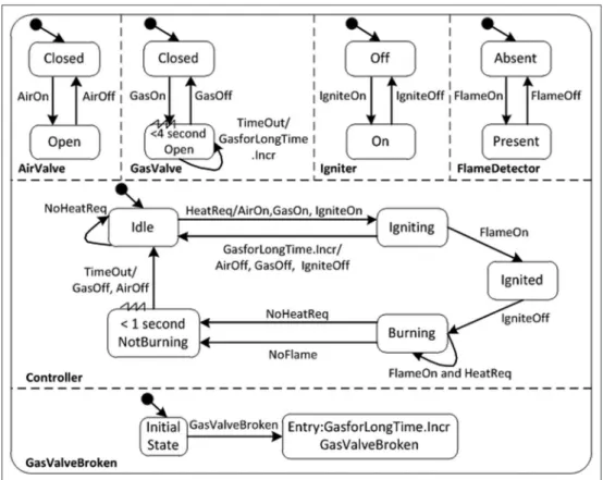
and stops working. Figure 8 is the SD of the gas stove control system according to the literature.17,18
Figure 9 is the FT of the gas stove control system according to the safety requirements17,19 which describes the fault problems causing explosion. When the gas overflows, air valve is open and flame monitor does not monitor the flame at the same time, trying to ignite or a short circuit can cause the gas stove control system to explode.
Figure 8. SD of the gas stove control system.
Building the FSD of the gas burner system
First, the BNF of the basic events and minimum cut sets of the FT are shown as below according to the
method of extracting and describing safety
requirements:
CutSet1 = (^, (^, AirPresent, GasLeak), IgniterStart), CutSet2 = (^, (^, AirPresent, GasValveBroken),
IgniterStart),
CutSet3 = (^, (^, AirPresent, GasLeak), ShortCircuit), CutSet4 = (^, (^, AirPresent, GasValveBroken),
ShortCircuit),
TopEvent = (_, CutSet1, CutSet2, CutSet3, CutSet4).
Combined with system SD, the AirPresent and IgniterStart of the FT are the basic events, which have the corresponding elements in the system SD. The ele-ment of the SD corresponding to AirPresent is Open, which is one state of the AirValve component; IgniterStart corresponds to transfer IgniteOn of the Igniter component. GasValveBroken and ShortCircuit are the external injection events which can find the cor-responding elements of the SD. As a result, two com-ponents must be added to the system SD to represent the two basic events. GasLeak belongs to the composite event. Only when the gas valve is opened over 4 s and the flame monitor cannot detect the flame is there a gas
leak. GasLeak can be expressed as
GasLeak = (,GasOpenT.4sec, FlameAbsent). The type of GasOpen.4sec is the Time which corresponds to Open state of component GasValve. FlameAbsent corresponds to the absent state of component FlameDetector. The FT in Figure 14 has five basic events. AirPresent and IgniterStart are the atomic events. ShortCircuit and GasValveBroken are the external injection events. GasLeak is the composite event which should be decomposed. Their Ids in the
safety requirements mapping table are from Event1 to Event5. GasLeak is decomposed into Event6 and Event7. The Argument properties of GasLeak should be filled into expression (Event6, Event7). According to the Id of each basic event and the filling rules of map-ping table, the minimum cut sets are updated as follows:
CutSet1 = (^, (^, Event1, Event2), Event4), CutSet2 = (^, (^, Event1, Event3), Event4), CutSet3 = (^, (^, Event1, Event2), Event5), CutSet4 = (^, (^, Event1, Event3), Event5).
According to the description of the safety require-ments and filling rules of safety requirement informa-tion table, the safety requirement informainforma-tion mapping table is shown in Table 8.
After filling the mapping table, the FSD is automati-cally built according to the algorithm in section ‘‘Transformation rules,’’ which is shown in Figure 10. In order to describe it more conveniently, we only give the transformation result of minimal CutSet1 and omit others.
Validation and analysis
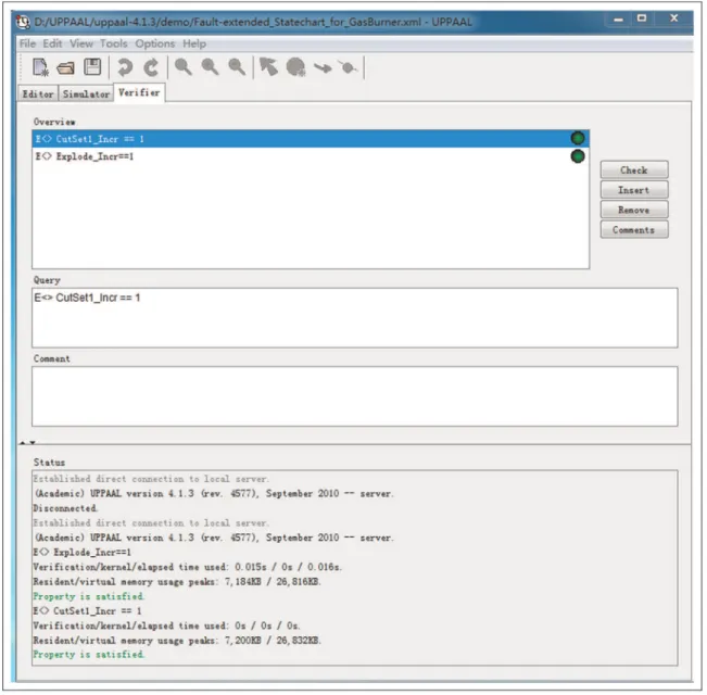
In the system, the occurrence of failure is usually related to the mistake of normal behavior combination or the order. Although the FT analysis can analyze which kinds of undesirable properties may lead to system fail-ure, it cannot judge whether there is such a problem in the design of the system. According to Figure 10, we get the timed automata model of the gas stove control sys-tem, which is shown in Figure 11.
In the timed automata model, state Explode corre-sponds to the fault state. When the integer variable Explode_Incr == 1, the system will immediately reach the state Explode. The accessibility of the fault state
Table 8. Semantic mapping table for the FT of the gas stove control system.
Id Name Type Complexity Element Component Argument
Event1 AirPresent Detectable Atomic State AirValve Open
Event2 GasLeak Detectable Composite None Event2 (^, Event6, Event7) Event3 GasValveBroken Injectable None None Event3 GasValveBroken Event4 IgniterStart Detectable Atomic Transition Igniter IgniteOn Event5 ShortCircuit Injectable None None Event5 ShortCircuit Event6 GasOpenT.4sec Time None State GasValve 4 s
Event7 FlameAbsent Detectable Atomic State Flame Detector Absent
Event8 CutSet1 CutSet None None CutSet1 (^, (^, Event1, Event2), Event4) Event9 CutSet2 CutSet None None CutSet2 (^, (^, Event1, Event3), Event4) Event10 CutSet3 CutSet None None CutSet3 (^, (^, Event1, Event2), Event5) Event11 CutSet4 CutSet None None CutSet4 (^, (^, Event1, Event3), Event5) Event12 Explode TopEvent None None TopEvent (_, CutSet1, CutSet2,
can be represented as E\.Explode_Incr == 1. Then, the formula will be input by the UPPAAL validator, and the verification results shown in Figure 12 indicate that the system has at least one path which can lead to system failure described by the top event of the FT. When the integer variable CutSet1_Incr == 1, the cir-cumstance described by minimum cut set CutSet1 will occur. Therefore, the minimum cut set can be repre-sented as E \. CutSet1_Incr == 1. And it can be input into the UPPAAL validator. The verification result which indicates the circumstance described by minimum cut set CutSet1 occurs is shown in Figure 12.
Minimum cut set CutSet1 contains three basic events, namely, AirPresent, GasLeak, and IgniterStart. According to Figure 10, the process for the system reaching the fault state is as follows: when gas valve has been opened for 4 s, it will trigger event Event2.Incr. If there is flame in this moment, it indicates that the
system is not ignited successfully, and the event Event2.Incr is triggered. Then, component Event2 will transfer from initial state into fault state, and entry action GasLeak.Incr is triggered. Due to no flame, the system keeps trying to be ignited and the event IgniterStart.Incr is triggered. In this case, the compo-nent AirValve is open and entry action AirPreset.Incr is triggered. Then, the minimum cut set CutSet1 is met, and the system will reach the fault state Explode, which indicates that the top event occurs.
To sum up, the gas burner control system does not meet the requirement that is ‘‘at all times, the gas con-centration in the surroundings of the gas burner should not exceed a certain threshold.’’ In order to meet safety requirements, once the gas valve has been open for 4 s or the system receives the GasValveBroken sig-nal, the system in state Igniting should be ignited and the valves should be closed at the same time and
returned to initial state Idle. The corrected system SD is shown in Figure 13.
Related work
In order to guarantee the safety and reliability of embedded airborne system, the safety analysis based on system models has become an important step in the sys-tem development cycle.
Generally, FT only applies to static analysis, but it cannot describe the temporal dependence and the dynamic behavior of system. In order to enable FT to support real-time and dynamic system modeling, aca-demia has conducted a series of research to extend cap-abilities of the FT. In Hansen et al.20and Schellhorn et al.21the temporal FT can describe temporal logic. The dynamic FT in Cˇepin and Mavko22 is applied to com-plex dynamic systems modeling and description through expanding the dynamic door. The component FT in Kaiser and Zocher23 and the state/event FT in Kaiser et al.24are used for component system modeling and analysis. In Walker and Papadopoulos,12the defi-nition of Priority door is first proposed to support the sequence dependence on the dynamic behavior
modeling. The FT in Palshikar25can express the quan-titative temporal relationship between basic events and the top event through expanding semantics of logic gates. In Walker et al.26and Domis et al.,27FT is used for the consistency verification. The approach in Yao and Jin28 implements the modeling of composite state in SD by constructing colored Petri nets. SD is con-verted into hierarchical automaton model for formal verification,29 while some work converted SD into colored Petri nets for consistency, completeness, and accessibility validation.30 The concept of linear tem-poral FT is proposed in Huang et al.,31 and the safety requirement described by linear temporal fault tree (LTFT) is expressed as linear temporary logic (LTL) formula for formal verification. In Koh and Seong32 and Cha and Yoo,33 the safety requirement described by FT is expressed as computation temporal logic (CTL) formula for safety verification of nuclear reactor control system. Reif et al.34propose how to apply FTA to SD. They point out that the SD should be built sepa-rately from the construction of the FT, but each mod-el’s construction process should be influenced by others. El Ariss et al.17,35 presented an approach for integrating FTA with SD, and the approach directly
mapped basic events to SD elements, but the mapping rules of this article are different from El Ariss17 and can solve some other aspect problems. Sa´nchez and Felder,18Sa´nchez et al.,36and Dasso and Funes37 pro-pose an approach by integrating the safety requirement described by FT with SD in order to generate test cases. Through the construction of the mapping table, Nazier and Bauer19build the safety-related test model and use model checking to generate test cases. An approach for integrating the safety requirement described by FT with functional model of the system is proposed in Ortmeier et al.38
Conclusion
In this article, we present the concept of FSD and give the method and process to construct FSD. It unifies
the safety requirement analysis model and functional model. FSD can also describe the system’s safety requirements and functional behaviors. In our approach, minimum cut sets are used as the smallest unit to describe the top event. If system can reach the fault state which corresponds to top event, it indicates that the SD of the system does not satisfy the safety requirements. Through FSD model, we can quickly find out the failure process and which software beha-vior or combination of software behabeha-viors results in the failure. Then, the SD will be corrected to satisfy the safety requirements. Finally, a case study of a gas stove control system is given to explain the feasibility and effectiveness of our approach.
Our approach provides a new idea for software safety analysis of safety critical system. In the future work, we will work on the following aspects in depth:
first, we will define conversion rules that transform other gates in FT into SD notations through the analy-sis of their semantics. The conversion rule for continu-ous time into SD notations is given in this article, and the conversion rule for discrete time will be given in the future. Second, the definition of the property will be perfected and some new properties will be added to the safety requirement mapping table. Third, sometimes there is the same sub-expression in the expression of minimum cut sets and the FSD can be reduced by the sub-expression. And the naming conversion when the safety requirements are transformed to SD notations needs to be perfected. The algorithm for constructing FSD automatically will also be reduced.
Declaration of conflicting interests
The authors declare that there is no conflict of interest.
Funding
This research received no specific grant from any funding agency in the public, commercial, or not-for-profit sectors.
References
1. Leveson NG. Software safety: why, what, and how.
ACM Comput Surv1986; 18: 125–163.
2. DoD US. MIL STD 882D standard practice for system safety. Washington, DC: U.S. Department of Defense, 2000.
3. National Aeronautics and Space Administration. NASA-STD-8719.13A-2003 software NASA technical standard. Washington, DC: National Aeronautics and Space Administration, 2003.
4. Peled DA.Software reliability methods. Berlin: Springer-Verlag, 2001, pp.1–3.
5. Huang Z-Q, Xu B-F, Kan S-L, et al. Survey on embedded software safety analysis standards, methods and tools for airborne system. J Software 2014; 25: 200–218.
6. Afshar A, Hajyhosseinloo M, Eftekhari A, et al. A report of the injuries sustained in Iran Air Flight 277 that crashed near Urmia, Iran.Arch Iran Med2012; 15: 317–319. 7. Yin Y, Liu B and Su D. Research on formal verification
technique for aircraft safety-critical software. J Comput
2010; 5: 1152–1159.
8. Roberts NH, Vesely WE, Haasl DF, et al.FT handbook. Washington, DC: Nuclear Regulatory Commission, 1981. 9. Harel D. Statecharts: a visual formalism for complex
sys-tems.Sci Comput Program1987; 8: 231–274.
10. Harel D. Statecharts in the making: a personal account. In: Proceedings of the third ACM SIGPLAN conference on History of programming languages, San Diego, CA, 9–10 June 2007, pp.1–5. New York: ACM.
11. Harel D and Politi M (1996)Modeling reactive systems with statecharts: The STATEMATE approach. Andover, MA: i-Logix Inc.
12. Walker M and Papadopoulos Y. Qualitative temporal analysis: towards a full implementation of the FT hand-book.Contr Eng Pract2009; 17: 1115–1125.
13. Yuge T and Yanagi S. Quantitative analysis of a FT with priority AND gates. Reliab Eng Syst Safe 2008; 93: 1577–1583.
14. Rauzy A. Mathematical foundations of minimum cut sets.IEEE Trans Reliab2001; 50: 389–396.
15. Chu TL and Apostolakis G. Methods for probabilistic analysis of noncoherent FTs. IEEE Trans Reliab 1980; 29: 354–360.
16. Harel D and Naamad A. The STATEMATE semantics of statecharts.ACM Trans Software Eng Meth1996; 5: 293–333.
17. El Ariss O, Xu D and Wong WE. Integrating safety anal-ysis with functional modeling. IEEE Trans Syst Man Cybern A2011; 41: 610–624.
18. Sa´nchez MA and Felder MA. A systematic approach to generate test cases based on faults. In: Proceedings ASSE2003, Buenos Aires, Argentina, 2003, http://cite seerx.ist.psu.edu/viewdoc/download?doi=10.1.1.114.7900& rep=rep1&type=pdf
19. Nazier R and Bauer T. Automated risk-based testing by integrating safety analysis information into system beha-vior models. In:2012 IEEE 23rd international symposium on software reliability engineering workshops (ISSREW), Dallas, TX, 27–30 November 2012, pp.213–218. New York: IEEE.
20. Hansen KM, Ravn AP and Stavridou V. From safety analysis to safety requirements.IEEE Trans Software Eng
1998; 24: 573–584.
21. Schellhorn G, Thums A and Reif W. Formal fault tree semantics. In:IDPT-2002, society for design and process science, Pasadena, CA, 23–28 June 2002, pp. 739–757. 22. Cˇepin M and Mavko B. A dynamic FT.Reliab Eng Syst
Safe2002; 75: 83–91.
23. Kaiser B and Zocher A. Bdd complexity reduction by component FTs. In: Proceedings of the European safety and reliability conference (ESREL 2005), Tri City, 27–30 June 2005, pp.1011–1019. Rotterdam: Balkema Publishers.
24. Kaiser B, Gramlich C and Forster M. State/event FTs— a safety analysis model for software-controlled systems.
Reliab Eng Syst Safe2007; 92: 1521–1537.
25. Palshikar GK. Temporal FTs. Inform Software Technol
2002; 44: 137–150.
26. Walker M, Bottaci L and Papadopoulos Y. Composi-tional temporal FT analysis. In:Proceedings of the 26th international conference on computer safety, reliability, and security (SAFECOMP 2007), Nuremberg, 18–21
September 2007, pp.106–119. Berlin, Heidelberg: Springer-Verlag.
27. Domis D, Hofig K and Trapp M. A consistency check algorithm for component-based refinements of FTs. In:
Proceedings of the international symposium on software reliability engineering (ISSRE), San Jose, CA, 1–4 November 2010, pp.171–180.
28. Yao S-Z and Jin M-Z. Formal modeling and analysis of UML statecharts. J Beijing Univ Aeronaut Astronaut
2007; 33: 472–476.
29. Latella D, Majzik I and Massink M. Towards a formal operational semantics of UML statechart diagrams. In:
FMOODS’99, Florence, 15–18 February 1999,
pp.331–347. New York: Springer.
30. Jiang J-L, Zhou X-Z and Sun Y-C. Modeling and real-time analysis for C4ISR system based on UML SD. Com-put Eng2006; 31: 15–17.
31. Ma L, Huang Z-Q, Xu B-F, et al. A FT analysis method supporting model checking.Comput Digit Eng2013; 41: 257–260.
32. Koh KY and Seong PH. SMV model-based safety analy-sis of software requirements.Reliab Eng Syst Safe2009; 94: 320–331.
33. Cha S and Yoo J. A safety-focused verification using software FTs. Future Generat Comput Syst 2012; 28: 1272–1282.
34. Reif W, Schellhorn G and Thums A. Safety analysis of a radio-based crossing control system using formal meth-ods. In:Proceedings of the 9th IFAC symposium on con-trol in transportation systems, Braunschweig, 13–15 June 2000, pp.289–294.
35. El Ariss O, Xu D, Wong WE, et al. A systematic approach for integrating FTs into system statecharts. In:
32nd annual IEEE international computer software and applications (COMPSAC’08), Turku, 28 July–1 August 2008, pp.120–123. New York: IEEE.
36. Sa´nchez MA, Augusto JC and Felder M. Fault-based testing of E-commerce applications. In:Proceedings of the 2nd international workshop on verification and validation of enterprise information system. IEEE transactions on sys-tems, man and cybernetics, part A: systems and humans, Porto, April 2004, pp.66–74.
37. Dasso A and Funes A (eds).Verification, validation and testing in software engineering. Hershey, PA: IGI Global, 2007.