Chemical Industry & Chemical Engineering Quarterly www.ache.org.rs/CICEQ
Chem. Ind. Chem. Eng. Q. 21 (1) 95−105 (2015) CI&CEQ
M. GARCÍA-DOPICO1
A. GARCÍA2
1Repsol S.A., Engineering
Department, Madrid, Spain
2
Faculty of Computer Science, Technical University of Madrid, Madrid, Spain
SCIENTIFIC PAPER
UDC 662.749.2:665.644.2 DOI 10.2298/CICEQ130918009G
MODELLING FLUIDIZED CATALYTIC
CRACKING UNIT STRIPPER EFFICIENCY
Article Highlights
• A new model for an FCC unit stripper is presented
• This model correlates stripper efficiency to all the important stripper variables • It models the evolution of the coke concentration against residence time of catalyst • It models the evolution of the stripper efficiency against steam flow
• It models the evolution of the required steam flow when the stripper temperature is increased
Abstract
This paper presents our modelling of a FCCU stripper, following our earlier research. This model can measure stripper efficiency against the most impor-tant variables: pressure, temperature, residence time and steam flow. Few models in the literature model the stripper and usually they do against only one variable. Nevertheless, there is general agreement on the importance of the stripper in the overall process, and the fact that there are few models is due to the difficulty to obtain a comprehensive model. On the other hand, the pro-posed model does use all the variables of the stripper, calculating efficiency on the basis of steam flow, pressure, residence time and temperature. The cor-rectness of the model is then analysed, and we examine several possible sce-narios, like decreasing the steam flow, which is achieved by increasing the temperature in the stripper.
Keywords: coke, modelling, simulation, efficiency, stripper, FCCU.
In the following we present a new model for the stripper of a fluidized bed catalytic cracking (FCC) unit, which adds to and improves upon earlier work [1-4]. Commercial FCC units are essential in the design of any modern refinery, and are controlled, simulated and optimized by means of complex models. Most of these are unpublished, although some, almost all of which are developed by univer-sity-based research groups, are accessible [5-13]. A quite new approach can be seen in papers by Zeydan [14] and Taskin et al. [15], where they use the fuzzy logic, from techniques of artificial intelligence, to deal with the highly complex non-linear relations between the FCCU variables, and it looks a very interesting and a very promising approach.
These FCC models are modelling the cracking reactions that take place in the riser. They also often
Correspondence: M. García-Dopico, Repsol S.A., Engineering Department, Méndez Álvaro nº 44, 28045 Madrid, Spain. E-mail: [email protected]
Paper received: 18 September, 2013 Paper revised: 24 February, 2014 Paper accepted: 24 April, 2014
model coke combustion in the regenerator. The strip-per, however, is very often overlooked, due to the difficulty of modelling it, although it is an indispen-sable component for the correct operation of an FCC unit.
Process in the stripper
The riser output is composed of a mixture of dif-ferent types of vaporized hydrocarbons, steam and spent catalyst. In the reactor vessel the hydrocarbons and the catalyst are separated, then the catalyst is sent to the stripper.
The key function of the stripper is mass transfer. The stripper is responsible for removing hydrocarbons entrained on the surface of the catalyst. These hydro-carbons stick to the catalyst during the cracking reac-tions that take place in the riser. The catalyst with the entrained hydrocarbons is fed in from the top and comes into contact with the stripping steam injected from the bottom. The steam displaces the bons entrained in the catalyst, pushing the hydrocar-bons upwards for retrieval in the distillation column with the other hydrocarbon vapours. Ideally, at the bottom stripper outlet, the catalyst should be sur-rounded exclusively by steam, for which purpose baf-fles are installed to improve contact and increase resi-dence time.
The stripper’s function is to release the ent-rained hydrocarbons to assure that only the coke enters the regenerator. There are three major reasons for this, as specified by [16]:
• To increase FCCU performance, as, the hyd-rocarbons recovered after being sent to the fraction-ator can be recirculated for cracking.
• To avoid dropping of unit throughput, as hyd-rogen produces 3.7 times more heat than carbon, as a result of which regenerator temperature rises dramatically. Being a constraint on unit operation, this would lead to a reduction in loading. Mauleon [17] states that coke hydrogen content can be reduced from 7 to 5% through proper stripping, lowering the regenerator temperature and providing for an inc-rease in unit throughput.
• To reduce catalyst activity loss, as a higher regenerator temperature combined with a greater amount of steam (from the hydrogen) destroys the catalyst’s crystalline structure, thereby reducing its activity.
According to Higgins et al. [18], a stripper is expected to assure that only 10% of the coke burned is cat-to-oil coke and that this coke has at most 5.5% hydrogen by weight. Wilcox [19] also indicates that hydrogen in coke of about 5–6 wt.% generally indi-cates good stripper operation. Additionally, the FCC unit will pollute less, as the smaller the quantity of coke burned in the regenerator is, the lower the CO2, SO2 emissions will be.
Then a proper stripper operation is a key factor for correct FCC unit operation, as a malfunctioning stripper would cause serious problems:
• More coke reaching the regenerator.
• Increased H/C ratio of the coke burned in the regenerator.
Apart from lowering unit performance (according to Baptista et al. [20] between 5 and 11% by weight of
the load processed in the stripper is retrieved), the effect of these two disorders is the same: an increase in regenerator temperature, because the first increases the amount of coke to be burned and the second increases the coke combustion heat.
Additionally, an expansion of FCC unit capacity, with the resulting increase in the amount of circulating catalyst, often results in an undersized stripper. The revamps undertaken and the patents proposed to inc-rease stripper capacity are indicative of its impor-tance, for example:
• Mauleon and Heinrich [21] consider inc-reasing the number of streams of steam in the strip-per to raise stripstrip-per efficiency and, therefore, its cap-acity. Specifically, they propose a revamp introducing a second stream of what they call prestripping steam. Baptista et al. [20] put forward a similar idea com-posed of two streams of steam, one in the stripper and another for prestripping. Also Amoco [22] uses three streams of stripping steam to improve stripper performance.
• Therefore, Letzsch [23] suggests that the best option for raising unit area stripper efficiency is to replace the baffles by structured packing. A similar idea can be found in [24]. They have observed in a pilot plant that the conversion with the packing and modified baffles was 3% higher than using the con-ventional disc and donut trays.
• Mobil [25] modifies the stripper by adding a heat exchanger through which the regenerated cat-alyst is circulated (moved by the regenerator flue gas) to raise the stripper operating temperature. Mobil justifies this interest in raising stripper temperature, claiming that a 55 °C temperature increase results in a 40–80% saving in stripping steam with no loss of efficiency.
Models in the literature
The authors that consider the stripper in their models are the following:
• Moro and Odloak [26] have a dynamic model of the whole unit. In the stripper, they perform a heat balance (without considering the stripping steam) to calculate how the temperature evolves over time.
• Gao et al. [27] have a model to analyse the gas-solids behaviour in FCC strippers but not the efficiency.
given the much larger contribution of the catalyst compared to the contribution of the stripping steam and of the adsorbed hydrocarbons. In addition, they evaluate the changes of the catalyst level in the stripper over time, but they do not evaluate the strip-ping efficiency. A very similar stripper model can be found from Malay et al. [8].
• McFarlane et al. [12] have an interesting model of the whole unit, Exxon Model IV, with a detailed description of the fluid dynamics. But they consider that the only important effect of the stripper is a loss of catalyst temperature, reducing the catalyst temperature by a constant amount.
• Hovd and Skogestad [28] have a complete model of the reactor and regenerator, but they view the stripper as a completely mixed reactor and they do not take steam flow into account in the heat balance. Additionally, they consider that stripping is effective, that is, it always works properly, for which reason they do not perform a material balance, then they cannot simulate a stripper fault or see what effect has a change in the stripping steam flow.
• Arbel et al. [9] have a very good and com-plete model of the reactor and regenerator, with a detailed description of the reactor kinetics. Regarding the stripper, they assume it is a well-mixed tank, with a linear stripping function (stripping efficiency is con-sidered to depend on the steam flow) and a constant temperature drop (no heat balance is performed in the stripper). The evolution of the coke on the spent catalyst depends on a stripping function. γ:
(
)
0.0002 0.0018 1 ks
γ = + − (1)
where s is the steam flow, k is the proportional factor and γ is the unstripped hydrocarbons. As it can be seen, they consider that the maximum unstripped hydrocarbons are 0.2% in weight and the minimum is 0.02% in weight.
• In their model Han and Chung [5] take into account all the parts of the reactor (feed vaporization section, reactor riser, disengaging-stripping section and reactor cyclones) and of the regenerator (dense bed, freeboard and regenerator cyclones). The disen-gaging-stripping section is modelled as a perfectly mixed continuous tank. The concentration of coke in the catalyst at the stripper outlet (CckST) is calculated from a minimum coke content attainable by stripping (CckST0) using the following expression:
0 0
lg
exp ss cRS ss
ckST ckST ss
E F F
C C k
F
= + −
(2)
where kss0 is a frequency factor, Ess is a stripping factor and FcRS, Fss and Flg are the catalyst, steam and feedstock flow, respectively.
• Fernandes et al. [29] have a complete model of the entire unit. The disengage-stripper section is modelled as a continuous stirred tank. The amount of coke on catalyst is calculated by an empirical strip-ping function based on pilot plant data (the data are not published in the paper):
, ,
ck ST ck RS
Y =Y +γ (3)
where Yck,ST and Yck,RS are the total coke content of catalyst in the stripper and in the riser outlet, respectively. The stripping function is calculated with the stripper temperature:
5.2113 0.00144TST e
γ − ×
= (4)
Most of the authors [7,8,12,26] have focused on dynamic models of the unit and are interested on how the stripper evolves over time. Only some of authors [5,9,29] were able to model a malfunction or a change in stripper efficiency, although they can be improved as:
• A change of stripper temperature cannot be modelled [5,9], even though there are many patents, like Mobil’s [25], proposing a temperature increase to raise stripper efficiency.
• What effect an increase of catalyst flow has on stripper efficiency cannot be modelled [9,29], as since residence time have not been take into account.
For all these reasons, this paper proposes a new stripper model that will take into account all the variables affecting its operation: pressure, tempera-ture, residence time and steam flow.
Mass balance
As Turlier et al. [30] mention, hydrocarbons react differently in the stripper, specifically:
• Paraffins crack to yield olefins.
• Polyaromatics condense.
• Naphthenes dehydrogenate.
Magnoux et al. [31] study these reactions and how coke composition evolves when subjected to stripping under nitrogen. For this purpose, they divide the coke components into five families, looking at how the lighter families evolve by cyclization, isomerisa-tion and hydrogen transfer towards the heavier ones.
The key effect of these reactions is that they homogenize coke, from which we can deduce that coke is uniform in the regenerator, although these reactions have hardly any effect on unit performance.
• As in recent years many developments have been made in the design of riser termination devices in order to achieve a better separation of the gas and solid phases, it is assumed that separation in the reactor vessel is immediate and there is no hydro-carbon overcracking. This assumption is also used by Fernandes et al. [32]. It allows also leaving the feedstock flow out of consideration when calculating the stripper efficiency.
• As the reactions have little influence from the viewpoint of the stripper, they will not be modelled, and this paper will focus on the primary function of the stripper, i.e., determining how many hydrocarbons are retrieved from the catalyst to the steam stream, without any component changes. This simplification is also used by Han and Chung [5].
If reactions are not considered, the mass bal-ance only specifies a transfer of material from the catalyst to the steam stream. Then, the mass balance is based on how to correctly correlate all the variables affecting stripping. These variables are:
• Temperature. As temperature rises, stripping improves. The problem is that temperature cannot be increased at will, because this would mean that the catalyst leaving the riser would have to be hotter, and this is impossible without affecting riser reactions. Therefore, alternatives such as heating the stripper with catalyst from the regenerator have been devel-oped [25].
• Pressure. As pressure rises, stripping becomes more difficult, because the partial pressure for vapor-izing hydrocarbons is greater. As an FCC is a pres-sure-balanced unit, pressure cannot be changed without affecting other regions.
• Steam flow. As steam flow increases, strip-ping improves, albeit up to a limit, above which its effect becomes negligible, since the stripper effici-ency is not directly proportional to the steam flow. This is the variable that refineries use to improve stripper efficiency, but when the above-mentioned flow limit is reached, the only option is to revamp the stripper.
• Catalyst residence time. For a defined strip-per, i.e., with a given section and length, this will depend on the catalyst flow. As the catalyst flow increases, residence time decreases and, therefore, efficiency falls. Although it has a significant impact, this variable is not used by the refineries as a unit capacity expansion usually leads to an increase in catalyst flow.
The problem with correlating these variables to stripping efficiency defined as:
100 he heout strip
he
m m
=
m
η −
(5)
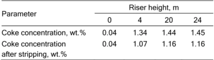
is that there are few data available on stripper operation in industrial or pilot plants. Additionally, some data are not very applicable. For example, Turlier et al. [30] analyse coke formation and what amount of this coke can be stripped, as shown in Table 1.
Table 1. Coke concentration in catalyst throughout the riser
Parameter Riser height, m
0 4 20 24
Coke concentration, wt.% Coke concentration after stripping, wt.%
0.04 0.04
1.34 1.07
1.44 1.16
1.45 1.16
This table clearly reveals the importance of stripping, as up to 20% of the coke can be retrieved, with the effect that this has on regenerator tempe-rature. However this analysis is useless for modelling the stripper, because it cannot be applied to calcul-ating stripping effectiveness. Furthermore, the authors were aiming for perfect stripping, for which reason they left the catalyst in a stream of nitrogen at 500 °C for an hour, far from actual process.
Due to this lack of accessible data, Couch et al. [33] built two scale models of strippers, simulating the working conditions of these plants but at ambient temperature. Thanks to the applied design improve-ments, they managed to reduce the regenerator tem-perature by 22 °F and to increase the catalyst/oil ratio by 6%. However, they do not mention the stripping efficiency achieved.
Rall and DeMulder [34] also built a pilot plant working at ambient temperature to simulate strippers, with a stripping region of height 190.5 cm (75") by diameter 66 cm (26"). They obtained interesting data using this pilot plant and analysed all the variables except for temperature, as the material they used, Plexiglas, cannot withstand high temperatures. Also they correlated efficiency against helium flow as they used helium instead of steam as a stripping gas.
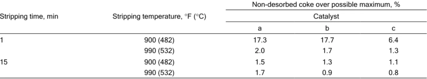
To examine the influence of temperature, we have consulted data from the literature [35], which analyses the influence of temperature and stripping time on three different catalysts, as shown in Table 2, where a, b and c are the three catalysts that they examined, whose properties are listed in Table 3.
reason it should be taken into account in stripper modelling (although it is pointless to assume 15 min, since the catalyst usually spends from 1 to 2 min in the stripper [16]).
Table 3. Characteristics of the analysed catalysts
Parameter Catalyst
a b c
Catalyst surface area, m2/g 439 389 105
Pore volume, cm3/g 0.89 1.8 1.14
Mean pore diameter, Å 72 184 436
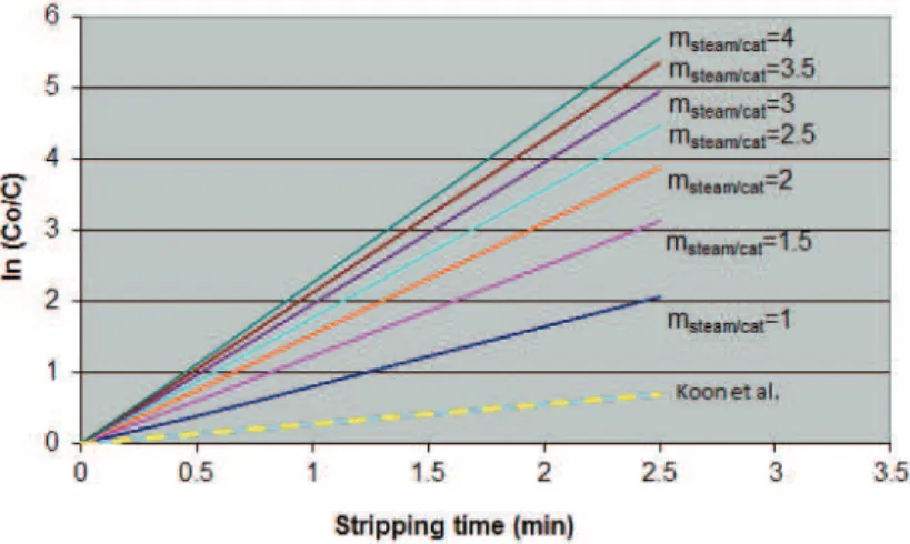
Figure 1, which shows the graph obtained by Koon et al. [36], is a better approach for examining the influence of residence time. At a pilot plant using nitrogen as the stripping agent, they analysed how the final coke concentration evolved with respect to the time the catalyst spent in the stream of nitrogen, as, instead of stripping efficiency, they plotted the logarithm of the initial coke concentration divided by the final coke concentration, ln(CO/C), which can be easily correlated to efficiency.
The goal for modelling the stripper is to get an equation that takes into account all the above-mentioned variables that can be used to calculate its efficiency and correctly reflects what influence the variables have, because, as we have seen, steam flow or temperature, among others, have a big impact on stripping efficiency.
The stripping efficiency is defined as the rained hydrocarbons removed divided by all the ent-rained hydrocarbons at the stripper inlet (maximum amount of strippable hydrocarbons), Eq. (5).
To know how many entrained hydrocarbons are in the stripper inlet it is necessary to use a riser kinetic model, such as proposed in [4], that makes a dis-tinction between the different generated coke types. The coke is classified by source into four categories:
• Catalytic coke, coke that is produced when a hydrocarbon is cracked on an acid catalyst.
• Contaminant coke, coke that is produced as a result of the presence of dehydrogenating pollutants (Ni, Cu, V or Fe).
• Additive coke, coke produced by those feed-stock fractions that are not volatile under riser working conditions (it is related primarily to Conradson Car-bon).
• Cat-to-oil coke, the fraction of the oil feed that is trapped or entrained in the catalyst. It is not really coke, as it has high hydrogen content.
Analyzing the stripping effects that were des-cribed in the literature review it can be obtained the following equation:
9445 12.5
/
100 1 1.6 0.225
strip strip
t
T strip
strip
steam cat P
= e
m
η
−
−
(6)
Stripping steam flow, residence time, stripper pressure and temperature are the key variables in this Table 2. Influence of temperature and time on stripping
Stripping time, min Stripping temperature, °F (°C)
Non-desorbed coke over possible maximum, %
Catalyst
a b c
1 900 (482)
990 (532)
17.3 2.0
17.7 1.7
6.4 1.3
15 900 (482)
990 (532)
1.5 1.7
1.3 0.9
1.1 0.8
equation. The geometry of each unit is reflected by calculating the residence time, which will be done taking into account the stripper height and section.
The Eq. (6) could be used to model strippers that use baffles, as simple, disc and donuts or packed, even if the equation does not consider what kind of baffle is used. In this case, the residence time should be multiplied by a height equivalent factor, as the residence time is related to stripper height, which can in turn be related to the number of stages men-tioned in [34], as a certain stripper height is equivalent to a stage.
This equation can calculate how many entrained hydrocarbons are retrieved in the stripper, yielding a new coke concentration for the catalyst entering the regenerator. Apart from filling a gap left by other models, the importance of this equation is that it can be used to ascertain what influence the different vari-ables have and thus calculate how much coke really enters the regenerator, thereby averting the danger of the regenerator temperature rising.
Enthalpy balance
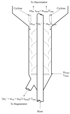
In the stripper, the deactivated catalyst, which comes from the riser at a temperature Tri_out and car-ries adsorbed coke and entrained hydrocarbons, comes into contact with the stripping steam, which is at a temperature Tsteam. The whole mixture will reach a total temperature of Tstrip. This is illustrated in Figure 2, which shows all the streams involved and their respective temperatures. The enthalpy balance is based on the vaporization of the entrained hydro-carbons and that the deactivated catalyst from the riser increases the steam temperature. As the hyd-rocarbons will be assumed first to be vaporized and then changing their temperature, the specific heat of the vapour phase will be used, getting the following equation:
(
)
_ _
_
) ' (
( )
(1 )
) (
ri out cat cat ri out strip c c strip
strip he lhe ri out strip
strip
he vhe strip steam steam strip steam he strip
he
m Cp T T m Cp T T
m Cp T T
m Cp T m Cp T T
m
η η
λ η
− + − +
+ − − −
− = − +
+
(7)
As the enthalpy balance reveals, a distinction is made between the coke and the entrained hydro-carbons, which, as mentioned earlier, are referred to as cat-to-oil coke. Strictly speaking, these hydrocar-bons are not coke (because they are hydrogen-rich hydrocarbons), most, being heavy hydrocarbons, tend
to be part of the feed that has not been vaporized or cracked. Therefore, the properties of the entrained hydrocarbons will be assimilated to the conditions of the feed rather than of coke. Specifically:
• The latent heat of vaporization of the ent-rained hydrocarbons used will be the same as for the feed.
• The specific heat of the vapour and liquid phased of the entrained hydrocarbons are the same.
• The specific heat of the entrained hydro-carbons will be equal to that of vapour phase feed.
These are valid assumptions as the mass of entrained hydrocarbons is small compared to the mass of the catalyst, and, additionally, there is little change in the temperature of these hydrocarbons in the stripper.
Figure 2. Scheme of the material and heat streams in the stripper.
Finding the stripper temperature, Tstrip, dividing by the mass flow of the feed, mF, and introducing some heat losses, which will be assumed to be a percentage of the total heat, we get:
(
_ / _ _ /)
_ /
(1 ) ( ( ) ' ) ( ) )
'
ri out steam
strip c C O F cat F cat C C steam F steam c C O F strip
strip
steam
cat F F
F cat C steam
c C O C
+ m / m + + m / m
-y Cp Cp y Cp T Cp T y
= T
+ (m / m ) + + ( / m )
y Cp Cp y Cp m Cp
α λ η
−
RESULTS
To analyse how well the proposed stripper model matches reality, we will look at what influence each variable has on the model. Then we will see if the results provided by the model are logical and tie in with reality and also we will compare them against measured data and results from others authors in the literature (Koon et al [36], Han and Chung [5] and Fernandes et al. [29]).
First, we will analyse how stripper efficiency evolves against residence time for different stripping steam flows. To be able to compare this with Figure 1, proposed by Koon et al. [36], ln(CO/C) will be used instead of efficiency in the graph. To be able to draw conclusions, stripper temperature (Tstrip = 510 °C) and stripper pressure (Pstrip = 2 kg/cm2) have been kept constant. The catalyst density is also considered to be constant (560 kg/m3). This yielded the graph shown in Figure 3. To calculate residence time, a stripper with a specific diameter and length was taken, modifying the catalyst flow through the stripper. The results from Koon et al. [36] are also shown in Figure 3 to compare them against our results (dashed line). Analysing this graph, we find that:
• For a given steam flow, the model outputs a very similar linear correlation to the one presented by Koon et al. [36], as shown in Figure 1, although resi-dence time, until 2.5 min (Figure 3) is less than 15 min (Figure 1) as such a long time does not make sense in a stripper of a commercial FCC unit since the catalyst usually spends from 1 to 2 min in the stripper [16]. This data can be corroborated in Table 4, where the key design operating conditions for industrial FCC unit strippers are shown [37]. In the Figure 3, the slope for Koon et al. is also lower but in their experiments there is not catalyst flow then it is not possible to compare the slopes.
• Increasing the steam flow improves the final coke concentration, although the greater the flow is, the less influence this has.
Table 4. Key design operating conditions for industrial FCC unit strippers
Property Value
Stripping steam severity, kg steam/1000 kg catalyst 2-4
Superficial steam velocity, m/s 0.15-0.30
Superficial catalyst flux, kg/(m2s) 30-75
Maximum restricted catalyst flux, kg/(m2·s) 250
Mean catalyst residence time, s 60-120
Stripper temperature, °C 495-565
Additionally, we are going to analyse the influ-ence of a packing that improves contact (as proposed by [23]) by achieving a greater equivalent height or that of a revamp increasing the length of the stripper. As mentioned above, packing will be modelled by multiplying the residence time by a factor. The strip-per has been assumed to have n different stages, each stage being 4.5 m high. To be able to draw conclusions, the catalyst flow (C/O = 4 for a feed flow of 3000 T/d), stripper temperature (Tstrip = 510 °C) and pressure (Pstrip = 2 kg/cm2) have been kept constant for the same stripper as modelled in Figure 3, with a diameter of 2.1 m, yielding Figure 4.
Analysing the graph we find that:
• It has a similar shape to a figure presented by Rall and DeMulder [34], but needs fewer stages and less stripping steam. This is because Rall and DeMulder’s [34] graph modelled the stripper at room temperature at which efficiency decreases consider-ably and needs to be offset by more steam and a longer stripper or by improving contact between steam and catalyst (packing). The curve shape fit quite well with the curve obtained from the equation of
Han and Chung [5] (dashed line), with n = 1. The figure shows that stripper efficiency is not a linear function with the steam.
• If contact or stripper length is increased by 33% (from n = 1.5 to n = 2.0), efficiency is increased by around 4% (when using 2.0 kg of steam/1000 kg cat.) or steam flow can be reduced by 35% (from 2.5 to 1.6 kg of steam/1000 kg cat.) without any loss of efficiency, which is equivalent to 93.0%.
• As in Figure 3, stripper efficiency is improved by increasing the steam flow, but it is clear that the same increase has less and less influence as the flow increases, as the curve levels out. When the limit is reached, efficiency cannot be improved by increasing steam flow and the stripper becomes too small, thus leaving no option but a revamp. The dependency of efficiency on steam flow is evidently not linear, con-trary to what is suggested by the model of Arbel et al.
[9].
Another variable to be analysed is stripper tem-perature and its effect. This is not normally a variable that can be juggled with as it is constrained by the riser. Solving the enthalpy balance set out above, we find that stripper temperature is about 3 °C lower than the riser outlet temperature. This tallies with plant data. However, if the stripper were heated with regen-erator catalyst, as proposed by Mobil [25], it would indeed become an operating variable, which would depend on how much regenerator catalyst is fed through the heat exchanger. We will analyse this heat exchanger option rather than the possibility of mixing regenerated catalyst with spent catalyst, because this only involves a heat balance, and neither the coke concentration in the catalyst nor catalyst activity have to be recalculated after mixing. The heat balance we looked at earlier is of course no longer valid, because another term has to be added to account for the cat-alyst from the regenerator (m'cat), which is assumed to enter at regenerator temperature and reach stripper
temperature, which is true if the heat exchanger is big enough. This way the heat balance would be:
_
_ _
' ( ) ( )
' ( (
(1 ) )
) (
cat cat reg strip cat cat ri out strip ri out
c c strip he lhe ri out
strip strip he vhe strip strip
steam steam strip steam he F strip
m Cp T T m Cp T T
m Cp T T m Cp T
m Cp T
T
m Cp T T
m
η η
λ η
− + − +
+ − + −
− − − =
= − +
+
(9)
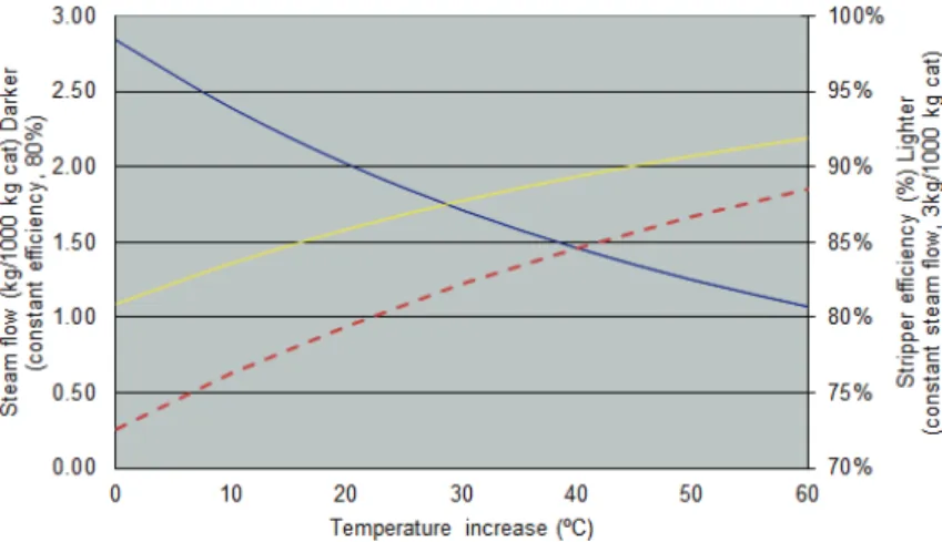
To be able to draw conclusions as above, the residence time (tstrip = 1 min) and stripper pressure (Pstrip = 2 kg/cm2a) have been kept constant. Starting from an initial stripper temperature of 510 °C, we have analysed how temperature increments of 10 °C influence both efficiency and steam flow, as shown in Figure 5:
• Increasing temperature raises stripper effi-ciency. Specifically, if increased by 60 °C, efficiency rises from 81 to 92% for a constant steam flow of 3 kg steam/1000 kg cat. The curve shape fit quite well with the curve obtained from the equation of Fernandez et al. [29] (dashed line).
• Increasing temperature decreases the required steam flow. Specifically, if increased by 60 °C, the required steam flow falls from 2.8 to 1.1 kg steam/kg cat. with no loss of efficiency, which is equivalent to 60%. This 60% reduction in steam flow for 60 °C is, evidently, in line with the claims of Mobil [25].
were changed. The result achieved, keeping the other variables – residence time (tstrip = 1 min), steam flow (3 kg steam/1000 kg cat.) and stripper temperature (507
°C) – constant, is shown in Figure 6.
By increasing the pressure from 1.5 to 2.5 kg/cm2, efficiency clearly falls from 84.2 to 75.3%. This means that, apart from not being an independent variable, it is the one that least affects stripper effi-ciency, although its influence is not negligible.
Then this model calculates stripper efficiency based on all the important stripper variables: steam flow, pressure, residence time and stripper tempera-ture and:
• Gives a prediction of the evolution of the final coke concentration against residence time that is comparable to data by Koon et al. [36].
• Gives a prediction of the evolution of efficiency against steam flow that is comparable to data by Rall and DeMulder [34] and the curve shape fit quite well with the curve obtained from the equation of Han and Chung [5].
• Indicates that stripper performance improves appreciably if contact is improved (by means of pack-ing, for example, as mentioned by [23]).
• Indicates that steam flow can be reduced by around 60% if the stripper operating temperature is increased by 60 °C, which are values in line with the specifications by Mobil [25]. The curve shape fit quite well with the curve obtained from the equation of Fer-nandez et al. [29].
• Indicates that stripper efficiency would be inc-reased if stripper operating pressure could be red-uced. However, pressure is not an operating variable that can be changed, as it is constrained by the rem-ainder of the unit.
CONCLUSIONS
In this paper, we have presented a new model for a FCCU stripper as the stripper is underestimated in most FCCU models. Only few models [5,9,29] can be used to calculate its efficiency, although these models do not consider all the operating variables for this purpose. As an indication of stripper importance, Figure 5. Influence of temperature vs. steam flow. Comparison with Fernandez et al. [29] (dashed line).
it may suffice to analyse the revamps of this equip-ment that are being undertaken and the stripper pat-ents that are continually being filed.
In this work, we have obtained an equation that calculates stripper efficiency based on all the impor-tant stripper variables: steam flow, pressure, resi-dence time and stripper temperature.
As the model fits reality, it seems reasonable to regard it as quite a rigorous and easy-to-apply model, although it does need a riser kinetics model, such as proposed by [4], that makes a distinction between the different generated coke types to ascertain how much cat-to-oil coke enters the stripper and then to cal-culate how much coke is retrieved. This stripper model is easy to integrate in a complete model of an FCC unit and it is helpful to know how much coke is really sent to the regenerator and how the coke rec-overed decrease the regenerator temperature.
Nomenclature
Cpc specific heat of the coke (kcal/(kg K))
Cpcat specific heat of the catalyst (kcal/(kg K))
CpF specific heat of the vapour phase of feed (CpF = Cpvhe) (kcal/(kg K))
Cpvhe specific heat of the vapour phase of ent-rained hydrocarbons (Cpvhe = CpF) (kcal/(kg K))
Cplhe specific heat of the liquid phase of entrained hydrocarbons (Cplhe = Cpvhe) (kcal/(kg K))
Cpsteam specific heat of the steam (kcal/(kg K))
mc mass flow of the coke (kg/h)
mcat mass flow of the catalyst (kg/h)
mF mass flow of the vapour phase feed (kg/h)
mg/cat gas flow, in kg/1000 kg of catalyst
mhe mass flow of the entrained hydrocarbons at the stripper inlet (cat-to-oil coke) (kg/h)
mheout mass flow of the entrained hydrocarbons at the stripper outlet (cat-to-oil coke) (kg/h)
msteam mass flow of the stripping steam (kg/h)
msteam/cat stripping steam flow, in kg/1000 kg of catalyst
m'c mass flow of the coke without entrained hydrocarbons (m'c = mc - mhe) (kg/h)
m'cat mass flow of the catalyst from the
regenerator (kg/h)
n stripper stages
Pstrip stripper pressure (kg/cm2)
tstrip catalyst residence time in the stripper (min)
Treg regenerator temperature (K)
Tri_out temperature at the riser exit (K)
Tstrip stripper temperature (K).
Tsteam stripping steam temperature (K)
yc_C/O entrained hydrocarbons or cat-to-oil coke yielded at the riser outlet (kg/kg)
y'c coke, not including cat-to-oil coke, yielded at the riser outlet (kg/kg).
Greek letters
αstrip percentage of heat losses at the stripper (%)
ηstrip stripper efficiency (%).
λF latent heat of feed (entrained hydrocarbons) vaporization (λF = λhe) (kcal/kg)
λhe latent heat of feed (entrained hydrocarbons) vaporization (λhe = λF) (kcal/kg).
REFERENCES
[1] M. Garcia-Dopico, A. Garcia, Rev. Ing. Quim. 27 (2005) 26-32
[2] M. Garcia-Dopico, A. Garcia, Rev. Ing. Quim. 28 (2005) 16-23
[3] M. Garcia-Dopico, A. Garcia, A. Santos Garcia, in Proceedings of 2nd Int. Conf. Adv. in Petrochemicals and Polymers, Bangkok, Thailand, 2007, pp. 207-208
[4] M. Garcia-Dopico, A. Garcia, A. Santos, Appl. Catal. A. 303 (2006) 245-250
[5] Han, C. Chung, Chem. Eng. Sci. 56 (2001) 1951-1971
[6] A. Secchi, M. Santos, G. Neumann, J. Trierweiler, Com-put. Chem. Eng. 25 (2001) 851-858
[7] J. Arandes, M. Azkoiti, J. Bilbao, H. De Lasa, Can. J. Chem. Eng. 78 (2000) 111-123
[8] P. Malay, B. Milne, S. Rohani, Can. J. Chem. Eng. 77 (1999) 169-179
[9] A. Arbel, Z. Huang, I. Rinard, R. Shinnar, A. Sapre, Ind. Eng. Chem. Res. 34 (1995) 1228-1243
[10] S. Kumar, A. Chadha, R. Gupta, R. Sharma, Ind. Eng. Chem. Res. 34 (1995) 3737-3748
[11] E. Mihalcea, G. Pop, G. Bozga, O. Muntean, Prog. Catal. 2 (1993) 33-46
[12] R.C. McFarlane, R.C. Reineman, J.F. Bartee, C. Geor-gakis, Comput. Chem. Eng. 17 (1993) 275-300
[13] Y.Y. Zheng, Comp. Chem. Eng. 18 (1994) 39-44
[14] M. Zeydan, Int. J. Ind. Eng.-Theory 15 (2008) 1-15
[15] H. Taskın, C. Kubat, Ö. Uygun, S. Arslankaya, Comput. Chem. Eng. 30 (2006) 850-863
[16] R. Sadeghbeigi, Fluid Catalytic Cracking Handbook, 2nd ed., Gulf Publishing Company, Houston, TX, 2000
[17] J. Mauleon, “Revamping FCC Units”, In Engelhard FCC Seminar, Bruges, Belgium, 1989
[18] R. Higgins, H. Dirkse, R. Wijk, Petrol. Tech. Q. (1999) 91- -98
[19] J. Wilcox, Petrol. Tech. Q. (2009) 25-35
[20] C. Baptista, H. Cerqueira, E. Moreira, A. Mansur, Bol. Tec. Petrobras 45 (2002) 284-293
[21] J. Mauleon, G. Heinrich, “R2R Process. The 21st Century FCC Technology”,in IFP Seminar, Paris, France, 1994 [22] Amoco, U.S. Patent 5,112,576 (1992)
[24] H. Cerqueira, C. Baptista, J. Fusco, Petrol. Tech. Q. (2004) 83-88
[25] Mobil, U.S. Patent 5,062,945 (1991)
[26] L. Moro, D. Odloak, J. Process Control 5 (1995) 29-39
[27] J. Gao, J. Chang, C. Xu, X. Lan, Y. Yang, Chem.Eng. Sci. 63 (2008) 1827-1841
[28] M. Hovd, S. Skogestad, AIChE J. 39 (1993) 1938-1953
[29] J. Fernandes, L. Domingues, C. Pinheiro, N. Oliveira, F. Ribeiro, Fuel 97 (2012) 97–108
[30] P. Turlier, M. Forissier, P. Rivault, I. Pitault, J.R. Bernard, in Fluid Catalytic Cracking III (1994) 98-109
[31] P. Magnoux, H. Cerqueira, M. Guisnet, Appl. Catal., A. 235 (2002) 93-99
[32] J. Fernandes, J. Verstraete, C. Pinheiro, N. Oliveira, F. Ribeiro, Chem. Eng. Sci. 62 (2007) 1184–1198
[33] K. Couch, K. Seibert, P. Opdorp, “Controlling FCC Yields and Emissions UOP Technology for a Changing Environment”, in NPRA Annual Meeting, San Antonio, TX, 2003
[34] R. Rall, B. DeMulder, “New internal for maximizing performance of FCC Catalyst Strippers”, in Twelfth Refining Seminar, San Francisco, CA, 2000
[35] G. Davison, Guide to Fluid Catalytic Cracking, Part One, Contributors: Davison Chemical Company, W.R. Grace & Company.-Conn., 1993
[36] C. Koon, F. Akbar, R. Hughes, Y. Tyagi, M. Castro, S. Martin, P. Hall, C. Snape, Chem. Eng. Res. Des. 78 (2000) 738-744
[37] J.S. Wiens, Experimental and Modeling Study of a Cold-Flow Fluid`Catalytic Cracking Unit Stripper, PhD Thesis, University of Saskatchewan, 2010.
M. GARCÍA-DOPICO1 A. GARCÍA2
1
Repsol S.A., Engineering Department, Madrid, Spain 2
Faculty of Computer Science, Technical University of Madrid, Madrid, Spain
NAUČNI RAD
MODELOVANJE EFIKASNOSTI KOLONE ZA
Č
IŠ
Ć
ENJE KATALIZATORA U POSTROJENJU ZA
KATALITI
Č
KO KREKOVANJE U FLUIDIZOVANOM
SLOJU
U radu je prikazano modelovanje kolone za čišćenje katalizatora postrojenja za katalitičko krekovanje u fluidizovanom sloju zasnovan na ranijem istraživanju. Ovaj model može odrediti efikasnost striping kolone u zavisnosti od najvažnijih promenljivih: pritiska, tem-perature, vremena zadržavanja i protoka. Nekoliko objavljenih modela obično opisuju kolone za čišćenje katalizatora u funkciji samo jedne promenljive. Ipak, postoji opšta sa-glasnost o važnosti striping kolone za celokupni proces, a činjenica da postoji nekoliko modela je možda rezultat teškoće da se dobije sveobuhvatan model. Sa druge strane, pretpostavljeni model zaista koristi sve promenljive kolone za čišćenje katalizatora i
izra-čunava efikasnost na osnovu protoka, pritiska, vremena zadržavanja i temperature. Ana-lizirana je korektnost modela, ispitivanjem nekoliko mogućih scenarija kao što su sma-njenje protoka koje se postiže povećanjem temperature u striping koloni.