Departamento de Engenharia Electrotécnica e de Computadores
Model Morphisms (MoMo) to Enable Language
Independent Information Models and Interoperable
Business Networks
By
Filipe André Sobral Correia
MSc. Dissertation presented at Faculdade de Ciências e Tecnologia of
Universidade Nova de Lisboa to obtain the Master degree in Electrical and
Computer Engineering, held under the guidance of
Doctor Ricardo Luís Rosa Jardim-Gonçalves
Lisboa
A
CKNOWLEDGEMENTS
I would like to thank all those who in some way contributed and supported me during the realisation of my course and this dissertation.
To my parents, brother and sister in-law who supported me from the beginning and throughout all these long years and never gave up on believing in me.
To Lua, my moonlight which guided me in these long seven years with many dark nights. Thank you for always being there and making me believing in myself.
To my advisor Doctor Ricardo Gonçalves for believing in my capabilities and giving me the honour of his advices, the time devoted to assist me and the assertive guidance towards the completion of this dissertation.
To all my colleagues at GRIS, especially to Carlos Agostinho, João Sarraipa and Fernando Ferreira, who took me as family and supported me from very closely.
A
BSTRACT
With the event of globalisation, the opportunities for collaboration became more evident with the effect of enlarging business networks. In such conditions, a key for enterprise success is a reliable communication with all the partners. Therefore, organisations have been searching for flexible integrated environments to better manage their services and product life cycle, where their software applications could be easily integrated independently of the platform in use. However, with so many different information models and implementation standards being used, interoperability problems arise. Moreover, organisations are themselves at different technological maturity levels, and the solution that might be good for one, can be too advanced for another, or vice-versa. This dissertation responds to the above needs, proposing a high level meta-model to be used at the entire business network, enabling to abstract individual models from their specificities and increasing language independency and interoperability, while keeping all the enterprise legacy software‟s integrity intact. The strategy presented allows an incremental mapping construction, to achieve a gradual integration. To accomplish this, the author proposes Model Driven Architecture (MDA) based technologies for the development of traceable transformations and execution of automatic Model Morphisms.
R
ESUMO
T
ABLE OF
A
CRONYMS
AP Application Protocol
ARM Application Reference Model
ASCII American Standard Code for Information Interchange
ATL ATLAS Transformation Language
BDA Behavioural Digital Aircraft
CAD Computer-Aided Design
CIM Computer Independent Model
DDL Data Definition Language
EEP Eurostep EXPRESS Parser
EE Extended Enterprise
EMF Eclipse Modelling Framework
EI Enterprise Interoperability
FP7 Seventh Framework Programme
GRIS Group for Research in Interoperability of Systems ICT Information and Communication Technology IDE Integrated Development Environments IEC International Electrotechnical Commission
ISO International Organisation for Standardization (http://www.iso.org)
IT Information Technology
ITU International Telecommunication Union
MDA Model Driven Architecture
MDD Model Driven Development
MDE Model Driven Engineering
MDI Model Driven Interoperability
MOF Meta Object Facility
MoMo Model Morphism
MRS MoMo Recommendation System
OCL Object Constraint Language
OMG Object Management Group (http://www.omg.org)
OWL Web Ontology Language
P2P Peer to Peer
PDM Product Data Management
PIM Platform Independent Model
PLC Product Life Cycle
PLCS Product Life Cycle Support
PLM Product Lifecycle Management
PSM Platform Specific Model
QVT Query/View/Transformation Language
SC Supply Chain
SME Small and Medium Enterprise
SQL Structured Query Language
STEP Standard for the Exchange of Product Data
SUS System Under Study
TTCN The Tree and Tabular Combined Notation
UML Unified Modelling Language
VE Virtual Enterprise
VO Virtual Organisation
W3C World Wide Web
XMI XML Metadata Interchange
XML Extensible Markup Language
T
ABLE OF
C
ONTENTS
1. Introduction ... 1
1.1. Research Framework and Motivation ... 5
1.2. Research Method ... 7
1.3. Research Problem and Question(s) ... 10
1.4. Hypothesis ... 10
1.5. Dissertation Outline ... 10
2. Information Modelling and Languages ... 13
2.1. Models and Meta-Models ... 13
2.2. Modelling Paradigms ... 16
2.3. Data Standards ... 18
2.3.1. STEP ... 19
2.4. Modelling Languages ... 20
2.4.1. Unified Modelling Language ... 20
2.4.2. EXPRESS ... 22
2.4.3. Others ... 24
3. Model Morphisms ... 25
3.1. Model Non-Altering Morphisms... 25
3.2. Model Altering Morphisms ... 26
3.2.1. Model Transformation ... 27
3.2.2. Model Merging ... 27
3.3. Model Morphism Ontology ... 28
3.4. Semantic properties of Model Morphisms ... 29
4. Model Driven Interoperability Foundations ... 33
4.1. Model Driven Interoperability Method ... 33
4.2. Model Driven Architecture ... 35
4.2.1. MDA Standards ... 37
4.3. Executable Transformation Languages ... 39
5. Morphisms for Model and Language Independency in Multi-Sized Business Networks ... 43
5.1. Conceptual Solution to Enable Hypothesis ... 43
5.1.1. MDA-based Framework for Language Independency ... 45
5.1.2. Model Morphisms Within the MDA-based Framework Scope... 47
5.2. The Central Meta-Model... 50
5.3. Knowledge-Base Mediator ... 55
5.4. Application Scenario ... 56
6. Proof-of-concept Implementation ... 59
6.1. Implementation Overview and Technology Used ... 59
6.1.1. Use-Cases ... 60
6.2. Implementation Steps ... 63
6.2.1. Step 0 – Central Meta-Model definition and Model Mappings ... 64
6.2.2. Step 1 – Eurostep EXPRESS Parser Model Validation and XML representation ... 67
6.2.3. Step 2 – EXPRESS Injector ... 68
6.2.4. Step 3 and 5 – Bidirectional EXPRESS transformations to Central Model ... 70
6.2.5. Step 4 – Central Models to Central Models (UC2) ... 73
6.2.6. Step 6 – Exporting EXPRESS Models back to text and/or XML ... 73
7. Implementation Testing and Hypothesis Validation ... 77
7.1. Testing Methodologies ... 77
7.1.1. iSurf Functional and Non-Functional Evaluation Methodology ... 78
7.1.2. ISO/IEC 9646 (ITU-T X.290) – Framework and Methodology for Conformance Testing of Implementations of OSI and ITU Protocols ... 80
7.1.3. Tree and Tabular Combined Notation (TTCN) – Test Notation Standard ... 82
7.1.4. Adopted Test Methodology ... 83
7.2. Requirements and Functionalities Evaluation ... 84
7.3. Functional Testing ... 86
7.4. Non-Functional Testing ... 90
7.5. Scientific Validation ... 92
8. Conclusions and Future Work ... 95
8.1. Future Work ... 97
9. References ... 99
10. Annex ... 105
10.1. Requirements and Functionalities of the System ... 105
10.1.1. Requirements ... 105
10.1.2. Functionalities ... 105
10.2. Modelling languages meta-models to Central Meta-Model mappings... 106
10.2.1. EXPRESS Mappings... 106
T
ABLE OF
F
IGURES
Figure 1.1 – Interoperability on all layers of enterprises [17] ... 3
Figure 1.2 – Classical research methodology [25] ... 7
Figure 1.3 – Variation of reliability and newness of publications [26] ... 8
Figure 2.1 – Relationship between models, meta-models, modelling languages and SUS ...14
Figure 2.2 –OMG’s four level meta-modelling architecture ...15
Figure 2.3 – Objectivist vs. Subjectivist approaches to data modelling [28]...17
Figure 2.4 – Simple example of an UML class diagram model ...21
Figure 2.5 – Simple example of an EXPRESS text format model ...22
Figure 2.6 – Simple example of an EXPRESS-G format model ...24
Figure 3.1 – Model Altering Morphism applied to Model A ...25
Figure 3.2 –Example of “1-to-1” and “n-to-1” relationships *61+ ...26
Figure 3.3 – Model Transformation ...27
Figure 3.4 – The Model Morphism Ontology [73] ...29
Figure 3.5 – Semantic mismatches examples ...31
Figure 3.6 – Abstracting and refining operations on models ...31
Figure 4.1 – Reference Model for MDI [81] ...34
Figure 4.2 – Levels of Model Driven Framework ...37
Figure 4.3 – Instantiation of the OMG's meta-modelling architecture with MDA open standards ...38
Figure 4.4 – QVT languages layered architecture...39
Figure 5.1 – High level abstraction framework of the conceptual solution ...44
Figure 5.2 – Framework for model and language independency based on MDA ...46
Figure 5.3 – Detail of the framework for model and language independency based on MDA ...48
Figure 5.4 – Central UML Meta-Model proposal...51
Figure 5.5 – Central Model representation of a simple model example ...54
Figure 5.6 – Structure of Knowledge-Base Mediator ...55
Figure 5.7 – Furniture Supply Chain example [1] ...56
Figure 5.8 – Catalogue example of two different enterprises ...57
Figure 5.9 – Application scenario ...58
Figure 6.1 – EXPRESS to EXPRESS model morphisms use-case (UC1)...60
Figure 6.2 – Data injection and Central Model to Central Model use-case (UC2) ...60
Figure 6.3 – Proof-of-concept Implementation Overview (UC1 and UC2) ...62
Figure 6.4 – Mapping Status of EXPRESS EXP2CM and CM2EXP ATL Rules ...66
Figure 6.5 – Simple Family EXPRESS text model...67
Figure 6.6 – Simple Family EXPRESS XML text model (output of EEP) ...68
Figure 6.7 – XML Meta-Model ...69
Figure 6.8 – Simple Family EXPRESS XML model (XML meta-model instance) ...70
Figure 6.9 – Simple Family XMI serialised EXPRESS meta-model instance after injection ...71
Figure 6.10 – Simple Family model as Central Model representation ...72
Figure 6.11 – Simple Family model as EXPRESS meta-model instance (output of “CM2EXP”) ...72
Figure 6.12 – Simple Family model extracted to XML from an EXPRESS meta-model instance ...74
Figure 6.13 – Simple Family model transformed into text from an EXPRESS meta-model instance ....74
L
IST OF
T
ABLES
Table 3.1 – Semantic Mismatches (based on [61] and [74]) ...30
Table 6.1 – Purpose of the used technologies and tools by the proof-of-concept implementation ....63
Table 6.2 –EXPRESS’ “EntityType” mapping to the Central Meta-Model (mapping extract)...64
Table 7.1 – Simplified example of a TTCN table test ...83
Table 7.2 – XML (text) to EXPRESS model (instance of EXPRESS meta-model) transformation test case ...86
Table 7.3 – EXPRESS model to Central Model transformation test case ...87
Table 7.4 – Central Model to EXPRESS model transformation test case ...87
Table 7.5 – EXPRESS model to EXPRESS text transformation test case ...88
Table 7.6 – EXPRESS model (instance of EXPRESS meta-model) to XML (text) transformation test case ...88
Table 7.7 –“Product concept identification” ATL transformations time measurements ...91
1. I
NTRODUCTION
Given the current globalised exponential evolution in technology and aggravated economical world state, enterprises need to maximize efforts to maintain a positive cash flow at the same time they continue to satisfy the needs of an ever changing market. By this, more and more enterprises realize that one important step to success in their business is to create new and innovative products, but the solution to do so resides in abandoning the idea of acting as an “isolated island” and start collaborating with others to be able to take advantage of new market opportunities. On the other hand, most enterprises using traditional business methods are not providing the expected efficiency [1]. A single company cannot satisfy all costumers‟ requirements and where once individual organizations battled against each other, today the war is waged between networks of interconnected organisations [2]. In fact, with the explosion of advanced Web technologies, knowledge-bases and resources are becoming available all over the world, levelling markets as never, and enabling organizations to compete on an equal basis independently of their size and origin [3].
Accomplishing strategic business partnerships and outsourcing, enables enterprises to take advantage not only of their core competences but also of methods and services others have. In this line, in order to be more competitive they also need to improve their relationships with customers, streamline their Supply Chains (SCs), and collaborate with partners to create valued networks between buyers, vendors and suppliers [1] [4] [5], i.e. activities and performance of others to whom they do business with are critical, and hence the nature and quality of the direct and indirect relations [6]. Nevertheless, the world is evolving to what is called today the third era of globalisation, where it is reduced to a tiny flat place where information can be exchanged and applied innovatively across continents, independently of races, cultures, languages or systems [3] [7]. Thus, leading to worldwide non-hierarchical networks which are characterised by collaboration and non-centralised decision making [8] such as Extended and Virtual Enterprises (EE and VE) [4] [9].
through faxes, phone calls, paper documents, and a wide range of proprietary systems [8] [12].
If systems are only partially interoperable, translation or data re-entry is required for information flows, thus incurring on several types of costs. In SCs if the lower tiers do not have the financial resources or technical capability to support interoperability, their internal processes and communications are likely to be significantly less efficient, thus harming the performance of the entire network. This way, achieving an interoperable state inside heterogeneous networks is still an ongoing challenge hindered by the fact that they are, intrinsically, composed by many distributed hardware and software using different models and semantics [13]. This situation is even worst in the advent of the evolution of the enterprise systems and applications, which such dynamics results in increasing the interoperability problem with the continuous need for models adjustments and semantics harmonization, since:
Retail and manufacturing systems are constantly adapting to new market and customer requirements, thus answering the need to respond with faster and better quality production;
New organizations are constantly entering and leaving collaboration networks, leading to a constant fluctuation and evolution of system models.
All these factors are making interoperability difficult to sustain [7]. Being the latter the capability which two systems have to understand one and other to function together, it is directly related with the heterogeneity of model languages, communication capabilities, databases and semantics. Differences in all these factors hide a great barrier to achieve the time-to-market symbiosis that can unleash a solution more valuable than the sum of its creators [1] [4] [5] [14]. Enterprise Interoperability (EI) is more than just a communication support: it is about sharing functionality and information between systems at different levels [14], and a software approach to maximize the benefits of diversity, rather than to integrate the different system into one. EI is a relatively recent term that describes a field of activity with the aim to improve the manner in which enterprises, by means of Information and Communications Technologies (ICT), interoperate with other enterprises, organisations, or with other business units of the same enterprise in order to conduct their business [15]. On the other hand, those different levels of communication can be framed in a five layers of interoperability as defined by the holistic approach to interoperability by the “Advanced Technologies for Interoperability of Heterogeneous Enterprise Networks and their Application” (ATHENA [16]) European project (depicted in Figure 1.1) [17]:
related to the organisation and the operations of an enterprise are addressed. They include the way an enterprise is organised, how it operates to produce value, how it takes decisions, how it manages its relationships (both internally with its personnel and externally with partners, customers, and suppliers), etc; The Knowledge layer deals with acquiring a deep and wide knowledge of the
enterprise, including knowledge of internal aspects such as products, the way the administration operates and controls, and so on, but also of external aspects such as partners, suppliers, relationships with public institutions, etc; The Application layer focuses on the ICT solutions which allow an enterprise
to operate, make decisions, exchange information (Data layer) within and outside its boundaries, and so on;
The Semantic dimension cuts across the business, knowledge, application, and data layers. It is concerned with capturing and representing the actual meaning of concepts and thus promoting understanding.
Figure 1.1– Interoperability on all layers of enterprises [17]
Since many organisations developed and purchased solutions software (positioned at the Application layer of Figure 1.1) based on their own needs, the required cooperation with others is not a trivial activity and business partnerships are less effective because of it, evidencing low level of interoperability. Interoperability is even more pertinent to SMEs, since through collaboration can unleash solutions to larger markets which could only be reached by large enterprises, therefore increasing both clients and chances to be successful. This way, EI is still a prominent research topic, with a wide number of open questions and challenges.
Interoperability, it identified the following relevant dimensions: Managing more rapid change / innovation; Adapting to globalisation;
Large integration / interoperability costs;
Difficulties in decision making (e.g. when to interoperate with other enterprises); Lack of business case for Enterprise Interoperability;
A change in the model of collaboration towards open innovation.
These dimensions led to what are called today as Grand Challenges, giving a strategic direction to the research work as a whole. Each of them is a global domain of research for reaching seamless Enterprise Interoperability:
1. Interoperability Service Utility, representing an overall system that provides enterprise interoperability as a utility-like capability. That system comprises a common set of services for delivering basic interoperability to enterprises, independent of particular IT solution deployment;
2. Web Technologies for Enterprise Interoperability, seeks to apply the concepts, technologies and solutions flowing from developments in Web technology to address the problems of Enterprise Interoperability;
3. Knowledge-Oriented Collaboration, which comprehends sharing of knowledge within an organisation of collaborative enterprises to the mutual benefit of the organisation partners;
4. A Science Base for Enterprise Interoperability is about creating a “science base” by combining and extending the findings from other established and emerging sciences, allowing EI solution providers to engineer solutions on rigorous, scientific theories and principles.
need-to-serve basis for interoperability of complex business networks, by language independent information models. This dissertation addresses research on this subject, proposing a Central Model common to the entire business network in a framework that enables the abstraction of individual models at their meta-level and increase language independency and interoperability, keeping all the enterprise legacy software‟s integrity intact. The strategy presented allows an incremental mapping construction, to achieve growing integration. To accomplish this, the author proposes Model Driven Architecture (MDA) [19] based technologies for the development of transformations and execution of automatic and executable Model Morphisms, also providing traceability and repeatability on them.
1.1. Research Framework and Motivation
Enterprises engaged in supply-chain relationships, whether as manufacturers, customers, suppliers, or providers of services, need to share a great deal of information in the course of their business activities. This way, interoperability can affect enterprises and global economy by having inherent costs associated with poor or even lack of interoperability. Various researches on this matter were elaborated in the last decade like “Economic Impact of Inadequate Infrastructure for Supply Chain Integration” [20] and “Interoperability Cost Analysis of the U.S. Automotive Supply Chain” [21]. The latter studies the impact of interoperability in the automobile industry. According to it, poor interoperability affects society‟s economic welfare in two ways: by increasing the cost of designing and producing automobiles and by delaying the introduction of improved automobiles.
This way, an increase in the cost of designing and producing a new vehicle may lead to an increase in the equilibrium price of automobiles and/or a reduction in the quantity of automobiles exchanged in the market. Depending on the structure of the market, the lost social surplus will be shared by consumers, who will pay higher prices, and producers, who will earn lower profits. On the other hand, a delay in the introduction of an improved automobile also imposes costs on consumers and producers, since the late introduction of a new product or service can lead to a loss in consumer surplus because consumers cannot benefit from the product‟s improvements until it becomes available. Delays in the production of intermediate products (parts and assemblies) can also increase the cost of design and production and cause bottlenecks in the automobile design and manufacturing process, leading to the inefficient use of capital and labour [21].
The increasing number of customers and suppliers can lead to an increase of the required number of computer-aided design (CAD) systems and translators used;
Engineer training and use of design standards for the development of CAD data can lead to data more usable by downstream functions.
Transversally to the various industrial sectors (e.g. automotive, furniture, aerospace, etc), typical areas of for incurring cost of poor interoperability include [22]:
Avoidance costs which are associated with preventing interoperability issues before they occur (e.g. the cost of developing translation software);
Mitigating costs are the resources required to address interoperability problems after they have occurred, such as manually processing data;
Delay costs arise from interoperability problems that cause delay in the introduction of a new product, or prolong the sale of a bespoke product;
Post-manufacturing interoperability costs, including the marketing and sale of a product, such as brochure development and populating website databases; Loss of market share resulting from delays, where customers turn to
alternative suppliers for a faster response;
Specification costs, the cost to a manufacturer of obtaining product data from product and material suppliers;
Future proofing costs are generally unknown costs that will be faced at some time in the future in order to integrate with new (currently unknown) system requirements.
This problem is addressed by Europe‟s 2020 strategy which aims to create jobs, and encourage 'green' economic growth and renewal, thus creating an inclusive society and guide Europe‟s economy out of the economic recession. The financial crisis has had a major impact on the capacity of European businesses and governments to finance investment and innovation projects [23], and the Europe 2020 strategy continues to invest on innovation with programmes like the Seventh Framework Programme for research and technology development (FP7) [24] and the future FP8.
maintain the interoperability state.
1.2. Research Method
The research method adopted in this dissertation is based on the classical research method [25] which is defined as following:
Figure 1.2– Classical research methodology [25]
The phases in Figure 1.2 can be defined and explained as following:
1. Research question / Problem: it is the most important step in a research, since it defines the “area of interest”, although it is not a declarative statement like a hypothesis. It has to be target of a feasible study and capable of being confirmed or refuted. Usually this question is complemented by a few secondary questions to narrow the focus. This is defined in section 1.3.
Due to the high influence of the prior work which may exist, iterations between steps 1 and 2 can be done.
Background observation is extensively addressed in sections 2, 3 and 4.
Figure 1.3– Variation of reliability and newness of publications [26]
3. Formulate hypothesis: a hypothesis states the “predicted” (as an educated guess) relationship amongst variables and is stated in a declarative form, brief and straight to the desired point. This hypothesis serves to bring clarity, specificity and focus to a research problem and is defined in section 1.4.
others in a feasible way. Theoretical design and proof-of-concept implementation are defined in sections 5 and 6, respectively.
5. Test hypothesis / Collect data: to evaluate the hypothesis proposed, it is necessary to evaluate the outcomes of the system / architecture designed. For this, a test battery should be defined and applied to it, and further simulation if necessary, applying possible multiple scenarios. For each test, data should be collected for further analysis and hypothesis validation. Addressing this matter, section 7.1 defines the testing methodology used to evaluate the proof-of-concept implementation.
6. Interpret / Analyse results: after all tests applied and data outputs collected, it is time to interpret and analyse the results. If applicable, qualitative and quantitative (e.g. descriptive and inferential statistics, clustering, etc.) data analysis should be applied to the results. These can lead to weakening of the confidence of the hypothesis, or even put in jeopardy all of the assumptions made in the very beginning of the research. This should not be interpreted has a failure, but as a way to improve the original approach and try another one with new expertise of the subject, re-iterating from step 1 or 2.
On the other hand, this is the step where, when positive results are attained, is possible to consider the future and define the recommendations for further research. Discussion regarding literature, research objectives and questions should be taken into account, and draw conclusions out of it.
Interpretation and analysis of results from the proof-of-concept implementation are presented in sections 7.2, 7.3, and 7.4.
7. Publish findings: the outcome of solids results (either in line of the original hypothesis or against it) should result in a contribution to the scientific community. Accordingly to the type of research, scientific papers should be written to present intermediate results (e.g. in conferences), consolidated results (e.g. in journals), and finalised with a dissertation about the hypothesis.
1.3. Research Problem and Question(s)
How can enterprises effectively collaborate without having to adapt their internal systems to each member of their business network?
o How can information models be dynamically integrated enabling transparent interoperability between heterogeneous enterprises?
o Can model morphisms be independent of technological details in order to be specified at management levels?
1.4. Hypothesis
By creating a common conceptual meta-model for systems information models, one is able to abstract from technological details and enable the establishment of semantic and structural morphisms, thus enabling network interoperability.
1.5. Dissertation Outline
In this section the current collaboration needs of enterprises and context of the contribution of this dissertation are presented, evidencing the need for new solutions to decrease the interoperability costs and entropy needed for sustainable enterprises collaboration.
Sections 2, 3 and 4 present the grand topics of background observation. Section 2 covers models and modelling languages, addressed in a bottom up perspective, covering the basis for modelling paradigms, model based standards and modelling languages. Section 3 takes this model basis to an upper level, by defining how models can be morphed and mapped between them, without covering a technology which implements these morphisms. Finally in section 4, interoperability framework solutions are addressed based on automated model morphisms, defining various levels of interoperability and automatism, as well as the technology available to implement an interoperability framework.
hybrid functional and non-functional testing methodology, and informs about the external scientific validation of the framework.
2. I
NFORMATION
M
ODELLING AND
L
ANGUAGES
Information modelling is defined by the construction of computer-based symbol structures, such as items, groups and relations which are able to capture and express the meaning of information, knowledge or system and organize it in a precise format which not only makes it understandable and useful to people [27] [28],but also able to be executed (if the language is able to be executed). An executable modelling language can amplify the productivity of skilled programmers, enabling them to address more complex and challenging problems, less focusing the code writing and more about the functional services which the system must provide. Given that information is becoming an ubiquitous, abundant and a precious resource, its modelling is serving as a core technology for information systems engineering, and with it modelling and simulation are quickly becoming the primary enablers for complex system design [29], since they can represent knowledge in an intricate and complex way and at various abstraction levels to allow automated analysis.
2.1. Models and Meta-Models
A model is a definition of some slice of reality which is being observed and interpreted, which is constructed through the use of abstract elements and relationships in order to match corresponding real elements and relationships. In some contexts (like Model Driven Development / Engineering – MDD / MDE), the reality / object in study is called System Under Study (SUS), defining the elements that exist in the system. Nevertheless, models can represent different aspects of one reality, derive from different natures or be created using different languages, paradigms, concepts and formalism levels [30].
Models must be written in a well defined modelling language, since the symbols and relationships that are used to model a SUS should support the unification principle, described both syntactic and semantically in a fixed and coherent way. The modelling language, in its turn, is described by a meta-model – a model specifying constructs and relationships used in a given modelling language, which makes solid defined statements about what can be expressed in a valid model of that particular modelling language. Hence, a valid model is only conformant to its meta-model, which is an imperative condition, when it does not violate any statement and constructs inherited or deducible from its meta-model.
relation, but applied to the definition of statements of statements.
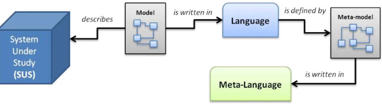
Figure 2.1– Relationship between models, meta-models, modelling languages and SUS
As depicted on Figure 2.1 a model describing a SUS is written in a modelling language which is conform to the semantics and syntax provided by its meta-model, and finally, the latter is written according to its meta-language.
A reflexive meta-model prevents the indefinitely increase of abstraction layers (model, language, meta-model and meta-languages layers), since it is expressed using the minimal set of elements of the modelling language to express the statements of the meta-model. This way, a meta-model is a self-describing model which self-conforms to its own semantics. A few examples of reflexive meta-models are OMG‟s Meta Object Facility (MOF) [31], and Ecore, which has been introduced with the Eclipse Modelling Framework (EMF) [32].
These relations between the multiple components of a modelling language was approached by the OMG‟s Model Driven Architecture (MDA), which considers that a model must be an instance of a well-defined meta-model, and can be classified according to the meta-modelling level they belong to. To confine the number of modelling layers to a manageable number, OMG has specified a reference meta-modelling architecture, limiting this number to four (see Figure 2.2). With this, is finally possible to perform operations on different models:
Level 0 – model level that is not possible to instantiate, it is called in various ways such as instance level or ground level (e.g. instances);
Level 1 – model level that has to be instantiated to obtain ground instances
(e.g., UML model);
Level 2 – known as the meta-model and describes the language itself (e.g.,
UML language);
Figure 2.2–OMG‟s four level meta-modelling architecture
In addition, InterOP [61] goes a little further, characterising a model according to four dimensions:
Meta-model: essentially modelling primitives, implemented in a meta-language; Structure: corresponding basically to the topology of the associated model‟s
graph;
Terminology: the labels of the edges or nodes of the models that don‟t refer to modelling primitives (e.g. “subclass” is not to be considered part of the terminological dimension of an OWL ontology);
Semantics: Given a “Universe of Discourse”, the interpretations that can be
associated with the model.
heterogeneous community.
2.2. Modelling Paradigms
Models and modelling is not a recent matter of engineering, since the discussion of the effectiveness of models is taken into consideration and traced back to the oldest known engineering textbook, by a Roman engineer from the first century B.C. [33].
Since modelling is a process of inquiry with intrinsic similarities with classis scientific theory construction, data modelling can‟t avoid philosophical assumptions. By applying a data model to information, systems or simply to some slice of reality, a philosophical analysis can be applied. On the other hand, there is a continuum between two radically conflicting views of the ontological nature of the data being modelled: the objectivist and the subjectivist extremes [28]. In the latter, a paradigm is characterised by the ontological and epistemological assumptions which are broad enough to the development of several practical approaches of data modelling within each one, such as Entity-Relationship, object-oriented languages or even LEGally Oriented Language (LEGOL) [34].
There are two basic ontological positions concerned with the modelled information, which are concerned with the nature of the modelled information:
Realism, postulates that empirical entities objectively given as immutable objects and structures of which the models are comprised, and the modelled information exists whatever the observer uses it or not. In realism, the real world exists and it is external and independent of the human / observer experience of it [35];
Nominalism, on the other hand, postulates that reality is a subjective construction of the mind and it is perceived and structured by socially transmitted concepts and names, hence, the construction of reality varies with the languages and cultures. In this view, there is no existence of an external reality, it is only in the mind of the observer and knowledge does not exist without the observer [36].
Epistemological assumptions define another two positions, which concern both with the nature of knowledge of the modelled information, and how it is acquired:
phenomena;
On the other hand, interpretivism approach denies the appropriateness of the casual model, holding that the data modeller must depend on his socially preconditioned and pre-understanding of the subject matter. By defending that knowledge can only be improved by applying the point of view of individuals directly involved on it, it is historically relevant to the frame of reference of both the data modeller and the individuals directly involved [28].
The epistemological and ontological dimensions give four possible paradigms by combination, where only two are primary significant for data modelling. While the first is based on a realist-positivist position, which defines an objectivist paradigm, the latter is based on a nominalist-interpretivist position, which defines a subjectivist paradigm. Therefore, any data modelling techniques can be located somewhere along the region between subjectivism and objectivism (in some literature “subjectivism” can also be referred as “constructivism”) [35] [36].
Figure 2.3– Objectivist vs. Subjectivist approaches to data modelling [28]
An approximate ranking of how some approaches to data modelling align on the subjectivist-objectivist continuum is depicted on Figure 2.3. From the left to the right:
Objectivism paradigm embraces the entity-based approaches to data modelling. For these approaches a data model is almost a mirror or picture of the reality observed, constructed from discrete chunks – entities. Entities have properties or attributes, which have an objective existence;
approaches. The idea is that one combines a description of data and processes it into a knowledge „frame‟, or „object‟. Frame-based approaches can be used to implement either subjectivist or objectivist interpretations of data, but is also possible to conceive them as predisposed towards subjectivism, since it difficult to define its contents and there are no objective rules to accomplish it. Unlike entities, sometimes frames are not perceived to exist in the observed reality as objective facts;
Subjectivist paradigm embraces the rule-based approaches, since these are heavily influenced by the subjectivist tradition. Its supporters see the data modelling as formalising the meaning of messages which are exchanged between professional communities. Since the expression of meanings must follow socially determined rules in order to facilitate the comprehension of what is being communicated, its supporters defend that meaning is created within the human mind and related to human purpose or intensions. Being the latter arisen from a socially constructed understanding of reality, emerging from social interaction and condition by social conventions / rules, they state that all computer data ultimately have to be interpreted in terms of their natural language meanings. Hence data can at best convey meaning from someone to someone, but no objective meaning can be had [28].
2.3. Data Standards
Dedicated to serious standard definitions multiple organisations with different application ranges exist, such as:
International Organization for Standardization (ISO) [38]; International Telecommunication Union (ITU-T) [39]; International Electrotechnical Commission (IEC) [40]; Open Applications Group (OAGi) [41];
Organization for the Advancement of Structured Information Standards (OASIS) [42];
Object Management Group (OMG) [43]; World Wide Web Consortium (W3C) [44].
2.3.1. STEP
ISO has been pushing forward the development of standards and models [38]. Efforts like STandard for the Exchange of Product Data (STEP) [45], have tried to deal with integration and interoperability issues.
STEP is a family of standards for the computer-interpretable representation of product information and for the exchange of product data under the manufacturing domain. It defines a framework which provides neutral mechanisms that are capable of describing products throughout their life cycle. The extent of standards required to support all the detailed characteristics of systems in the PLC, leads to highly complex models, i.e. Application Protocols (APs). These, are the STEP foundations for data exchange, enabling direct communication to be established among several stakeholders within an industrial sectors. APs are described using EXPRESS (ISO 10303-11) [46], which is the STEP modelling language.
and have better tools support.
Hence, for the representation of data corresponding to an EXPRESS schema, the STEP Part 28 (ISO 10303-28) specifies the mapping of type definitions and element declarations to XML Schema (XSD [49]), and the rules for encoding conforming data in XML according to certain configuration directives [50]. STEP Part 25 (ISO 10303-25) has similar purposes at the model specification level, detailing a mapping of EXPRESS constructs into the UML Interchange Meta-model, i.e. the XMI standard [51] [1].
2.4. Modelling Languages
Modelling language are artificial languages designed such way that they define a consistent set of rules to represent information, knowledge or systems in a structure. The rules are used for interpretation of the meaning of components in the structure, which usually represent real objects, interactions, behaviours or systems. There are countless modelling languages, with completely different types (e.g., graphical, object-oriented, algebraic, etc), but in the next sections a few relevant ones (in the context of interoperability) are going to be addressed.
2.4.1. Unified Modelling Language
Unified Modelling Language (UML) [52] is currently OMG's most-used specification and the de facto industry standard modelling language for visualising, specifying, and documenting software systems. It combines techniques from data, business, object and component modelling aspects throughout the software development life cycle, and across different implementation technologies [53].
UML models can be represented both textually and graphically. The latter specifies several diagram types, which can be classified into three categories: structure, behaviour and model managing diagrams.
Structure diagrams describe the static application structure of the system which is being modelled, also known as System Under Study (SUS). These are the Class, Object, Component and Deployment diagrams.
Behaviour diagrams describe the dynamic behaviour of the SUS. Therefore Use case, Sequence, Activity, Collaboration and State-chart diagrams, are the behavioural representations of the SUS.
describe how to organise and manage application modules.
Finally, as will be explained in section 4, UML is the core standard used to develop the Platform Independent Model (PIM) and Platform Specific Model (PSM) in the context of Model Driven Architecture (MDA). Besides its powerful modelling mechanisms, it has other features that are essential in an MDA environment, such as extension mechanisms – the UML Profiles, which are described in the next section.
Figure 2.4– Simple example of an UML class diagram model
Depicted in Figure 2.4 is a simple example of an UML class diagram model.
2.4.1.1. UML Profiling
An UML profile is an UML package stereotyped “profile”, which extends the UML language to accommodate new constraints, syntactic elements, or even to restrict it. It can be used as an extension of a meta-model, another profile, or even to define a new language without the need of creating it from scratch [54]. Typically an UML Profile is made up of three basic mechanisms [55]:
Stereotypes: are specializations of the meta-class “Class”. They define how it can be extended and may extend one or more meta-classes;
Tagged Values: properties of a stereotype and are standard meta-attributes; Constraints: are conditions or restrictions expressed in natural language text or
even in a machine readable language such as OCL [56].
meta-model, linking it to destination model basic constructs. Once the Profile is well defined, an executable transformation language can be applied to it (e.g. ATLAS Transformation Language – ATL) and achieve morphism automation from a model conforming to the defined profiled meta-model. The final result is an UML model, which also conforms to the profile created.
2.4.2. EXPRESS
EXPRESS (ISO 10303-11) [46] is a modelling language combining ideas from the entity-attribute-relationship family of modelling languages with object modelling concepts. It is used to describe the STEP information models in a textual format. It can represent complex inheritance relationships and functions, and includes a rich set of constructs for specifying constraints on populations of instances [57]. EXPRESS being mainly based in the entity-attribute relationship model, but not limited to it, since encompasses several characteristics from other languages such as C, C++, Pascal, SQL, etc. With this close bound with those languages, it has an object-oriented flavour, inheritance mechanisms among the entities constituting the conceptual model, and a large variety of types, thus becoming a very powerful modelling language.
Figure 2.5– Simple example of an EXPRESS text format model
Some important characteristics of EXPRESS are [58]:
Human-readable: although having a formal syntax, i.e. not based on a natural language, it can be read and used to communicate between people without any ambiguity, facilitating the instant understanding of STEP information models; Computer-interpretable: by having a formal and well defined syntax, it allows
SCHEMA Family; ENTITY Person
ABSTRACT SUPERTYPE OF (ONEOF (Male, Female)); name: STRING;
mother: OPTIONAL Female; father: OPTIONAL Male; END_ENTITY;
ENTITY Female
SUBTYPE OF (Person); END_ENTITY;
ENTITY Male
SUBTYPE of (Person); END_ENTITY;
its models to be processed by computer tools. With this is possible to validate the conformance (i.e. realise conformance testing) of STEP-based messages, which fundamental for successful communication [59]. With this, data exchanged can be cross-checked with the respective information models, to determine whether they are valid or not;
Technology and platform independent: EXPRESS is designed for conceptual product data modelling, hence its information models are described without any specific technology or implementation details, allowing them to be mapped into any implementation form. This feature combined with the previous one makes it possible to generate different software artefacts (e.g. software code, database structure, etc) from the same information model.
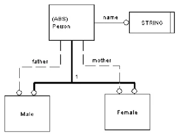
A simple example of an EXPRESS model is depicted in Figure 2.5. The main constructs which can be evidenced in the EXPRESS language are:
Schemas and Interface specifications: Schemas support the definition of modular information models, i.e., every model consists of one or more schemas, each with specific data definitions of a given scope. On the other hand, the interface specifications (USE FROM and REFERENCE constructs) enables data definitions defined in one schema to be visible in others;
Entities and attributes: Entities are the basic units for data definition in EXPRESS, describing classes of real world with associated properties. Properties are represented as attributes of the entities and depending on their types they can be simple values (e.g. string, real, etc) or relationships to other constructs (e.g. entity reference, redeclaration, refining type, etc);
Types: describe the domain of values that which an attribute can represent. EXPRESS defines the basic built-in types (e.g. string, real, date, etc) but one can define new types at the cost of the built-in types;
Constraint Rules: are constructs that allows the definition of restrictions for the values and relationships among the data definitions in a schema. This allows the definition of complex and intricate models, which can be checked for conformance not only at the syntax level, but also at the semantic level.
Figure 2.6– Simple example of an EXPRESS-G format model
2.4.3. Others
Besides UML and EXPRESS modelling languages, there are others broadly used for multiple purposes. A few examples are:
XML Schema (XSD) [49] is a language for expressing constraints about XML documents. There are several different schema languages in widespread use, but the main ones are Document Type Definitions (DTDs), Relax-NG, Schematron and W3C XSD (XML Schema Definitions), adding to XML the ability to define element and attribute content as containing values such as integers and dates rather than arbitrary text;
3. M
ODEL
M
ORPHISMS
Model Morphism, originally from mathematics, is the abstraction of a structure-preserving process between two mathematical structures, but applied to data models [61] [62]. This term only recently has been used in ICT systems and models, thus this new usage of “morphism” has the same inherited concept. This new application was introduced by the international research project INTEROP-NoE [63] with the aim of representing all kinds of, unary or binary, operations (i.e. mapping, merging, transformation, composition or abstraction) between two or more model specifications that may be described in different languages. On the other hand, models can be approached as graphs, since graphs are well suited to describe the underlying structures of models, especially transformations of visual models which can be naturally formulated by graph transformations [64].
Figure 3.1 illustrates a Model Altering Model Morphism between two models (the source “A” and target “B” models), where when it is applied to the source model it results on a different target model [61].
Figure 3.1– Model Altering Morphism applied to Model A
Model Morphisms are usually expressed with a certain degree of formalism. Therefore, following well formed structures expressing non-ambiguously the representation, the approach, the derivation law, the policies, the transformation system and the transformation constraints, is fundamental [65].
Concerning their classification, Model Morphisms can be non-altering and altering morphisms [66], as detailed in the following sections.
3.1. Model Non-Altering Morphisms
second [61]. These relationships can be assigned as “1-to-1”, “1-to-n” and “m-to-n”.
When one element of one source model corresponds exactly to one element of the other one, in this case the relationship can be designated as “1-to-1”. However, one can map a single element to a sub-graph of multiple elements in the second model (“1-to-n” relationship), or even from a sub-graph of elements from the first model to multiple elements in the second model, thus “m-to-n” relationship. These relationships are depicted in Figure 3.2.
Formalising: “Let M be the set of all inner-relationships of a model‟s elements in some
language, a non-altering morphism is a relation ,A,BM, where
Sub
A Sub
B , where Sub
X is a sub-graph of relationships of X”.Figure 3.2– Example of “1-to-1” and “n-to-1” relationships [61]
The concept of model mapping is advised as being a result of a process of constructing the mapping, called “mapping discovery”. This process should find the mappings in a semantically meaningful way, i.e. semantically identical/equivalent structures in both models should be discovered [61].
3.2. Model Altering Morphisms
3.2.1. Model Transformation
The main objective behind model transformation consists in transforming a source model A into a target model B, by means of modifying the first one by a function Ŧ. There are several techniques for achieving model transformations, at various levels, such as the top level “model-to-model” and “model-to-text” techniques [67]. One of the most common one is the “Meta-model Approach”, by OMG [68]. The key premise behind this technique lies on the conformity of each model to its own meta-model, i.e. both A and B models must conform to its correspondent meta-model (MMA and MMB, respectively). These meta-models define the languages used to build each model A and B. By establishing correspondences between each meta-model constructs, a complete mapping/function (Ŧ) is obtained between them. This function can be a simple table relating multiple or single constructs from both meta-models, but once it is created it can be later implemented by using more formal and executable languages (such as ATL, QVT, etc.). The use of these executable languages enables the automatic execution of the transformation Ŧ of a given input model conforming to meta-model MMA into an output model conforming to MMB, but not limited to this scenario since one-to-one model transformations is only one kind of transformations possible [69].
Model transformation has some differences from model mapping, which are: 1. While a model transformation is a function, a mapping can be a relation;
2. Domain and range of mappings and transformations are different. Particularizing, mappings can only exist if the input models are given in advance.
Figure 3.3– Model Transformation
Formalising: “Let M be the set of all inner-relationships of a model‟s elements in some language, A,BMand a function Ŧ: M1 → M2, a model altering morphism is Ŧ, having Ŧ(A) = B”.
3.2.2. Model Merging
for the model transformation, but preserving all original semantics from the input models. This means that there is no fundamental difference in considering multiple input models as a unique aggregated model, a set of disjoint graphs, one for each input model, which are joined through a mechanism of multiple inputs and a single output [61].
Formalising: “Let M be the set of all inner-relationships of a model‟s elements in some language, A,B,CMand a function Ŧ: (M1,M2) → M3, a model altering morphism is Ŧ, having Ŧ(A,B) = C”.
3.3. Model Morphism Ontology
INTEROP-NoE consortium facilitated the definition and usage of Model Morphisms by developing a Model Morphism Recommendation System (MRS [70]), which is a centralized knowledge repository of Model Morphisms. This way, if someone is looking for Model Morphism in order to answer his needs, he can search for specific details on the MRS and obtain the available Model Morphism(s) that meets his criteria. In order to this system be available to the public, they created a web portal [71] and defined an ontology [72] to classify the existing Model Morphism solutions, as is depicted in Figure 3.4, as an UML class diagram.
This way, Model Morphisms in MRS are classified according to the Model Morphism Ontology, allowing users to search for those which meet their needs. Here is some of the ontology concepts used to catalogue the Model Morphisms on the MRS:
EnablingTechnology: technologies that realize a model operation (Methodology, SoftwareTool or ModellingLanguage – i.e. the Meta-model); ModelOperation: every kind of manipulation that can be performed on one or
more models (ModelCreation, ModelProcessing);
ModelCreation: steps undertaken during the process of model building;
ModelProcessing: operations that can be performed on models once they are created (ModelTransformation, ModelMorphismDiscovery);
ModelMorphismDiscovery: operation that takes as input at least two models and returns the model correspondences discovered among them;
ModelTransformation: operation that takes as input one or more models and returns as output a correspondent model;
model translation, etc.);
Approach: method or methodology applied for realizing a ModelTransformation (e.g. graphs, programming language, etc.).
Figure 3.4– The Model Morphism Ontology [73]
3.4. Semantic properties of Model Morphisms
In the previous sections an analysis has been made over model morphisms but mainly focused on the structural inner-relations changes. On the other hand, one can particularly analyse the effects on the semantic. Since morphisms changes the structural inner-relations of the operand model(s), one must admit that a change to its semantics is at least plausible. InterOP NoE [61] makes a proposal to classify morphisms accordingly to the type of alterations they produce in the model, either altering it or leaving such semantics unaltered and so forth.
the relationship being established in the mapping:
In lossless cases, the relating element can fully capture the semantics of the related;
In loss mismatches, a semantic preserving mapping to the reference model cannot be built.
Mismatch Description
Lo s s le s s
Naming Different labels for same concept Granularity Same information decomposed (sub)attributes
Structuring Different design structures for same information (see Figure 3.5)
SubClass-Attribute
An attribute, with a predefined value set (e.g. enumeration) represented by a subclass hierarchy
Schema-Instance
An attribute value in one model can be a part of the other‟s model schema (see Figure 3.5)
Encoding Different formats of data or units of measure (e.g. USD and EUR)
Lo
s
s
Content Different content denoted by the same concept
Coverage Absence of information
Precision Accuracy of information (see Figure 3.5) Abstraction Level of specialisation (e.g. “Car” and “Ford”)
Table 3.1– Semantic Mismatches (based on [61] and [74])
On the other hand, transformations can be classified as:
Semantics preserving transformations, in which the semantic content of the source model is equivalent to the semantic content of target model;
Semantics enriching transformation in which the semantic content of the source model is contained in the semantic content of target model;
Semantics abstracting transformation in which the semantic content of the source model contains the semantic content of target model;
Figure 3.5– Semantic mismatches examples
In section 2.1 models were characterised accordingly to meta-model, structure, terminology and semantics. With these four dimensions and the basic relations of equivalence and inclusion, one can have all the possible combinations of these features. Hence, transformations can be classified accordingly to the alteration of one or more of the meta-model, structure, terminology and semantics dimensions. By analysing the alteration, the result can be without loss of information, expressiveness power, or abstracting / refining ones. Figure 3.6 depicts the inter-level transformations which can occurs and the refinement / abstraction relations throughout the defined OMG model levels.
4. M
ODEL
D
RIVEN
I
NTEROPERABILITY
F
OUNDATIONS
Model Driven Development (MDD), sometimes also referred as Model Driven Engineering (MDE), is an emerging practice for developing model driven applications. Its defining characteristic is that software development focus on models rather than computer program functionalities [75]. This way it is possible to express information models using concepts that are less bound to the underlying implementation technology and closer to the problem domain relative to most popular programming languages. When compared to these, models are easier to specify, verify, understand and maintain, thus widening the creation of new systems to domain experts, instead of only computing specialists to do so. One key premise behind MDD is that code can be automatically generated from the corresponding models, elevating, once more, the level of abstraction at which developers operate, reducing both the amount of development effort and the complexity of the software artefacts that the developers use [76].
Since the past two decades, level of software abstraction has been raised, for example, by using more expressive object-oriented languages (JAVA, C#, C++, etc), rather than less abstract Fortran or C [77]. MDD‟s vision does it again, by invoking a unification principle – “everything is a model”, the same way that the object-oriented languages invokes that “everything is an object”. Thus, the need for increase of software abstraction is not new, and MDD beside being the latest approach to do so, it introduces model abstractions at the various stages of the software life cycle, representing an evolutionary step of past efforts to create methods, languages and technologies to further elevate the abstraction level and increase the productivity and quality of the software development process [58] [78] [79].
Another key feature in MDD is the support of model at different levels of abstraction, from the high-level models focusing on goals, roles and responsibilities, to the bottom-level use-cases and scenarios for business execution. Supporting these principles can only be attained through mechanisms that perform operation on models and ensure traceability and consistency between them throughout the different levels of abstraction [58] [80].
4.1. Model Driven Interoperability Method
enterprises performances, and it is supported by the conceptual framework (MDI Framework or Reference Model for MDI) through the extensive use of models in vertical and horizontal integration of the multiple abstraction levels defined in the Reference Model for MDI [81] [82] [83]. This method, as detailed on Figure 4.1, introduces different conceptualization levels to reduce the gap between enterprises models and code level during the model transformation of MDD and Model Driven Architecture (MDA) sub-domains, and uses a common ontology to support the transformations and to solve semantic interoperability.
Figure 4.1– Reference Model for MDI [81]
The definition of the several levels in the Reference Model for MDI was based on the MDA, which defines three levels: Computation Independent Level (CIM), Platform Independent Level (PIM) and Platform Specific Level (PSM). As one can observe on the Reference Model for MDI, when compared to an MDA approach, has divided the CIM level into two sub-levels, the Top CIM Level (TCIM) and the Bottom CIM Level (BCIM). This was done in order to reduce the gap between the CIM and PIM levels. This decomposition of the original CIM level lead to different characterizations for TCIM and BCIM:
Top CIMis used to represent a company from the “holistic” point of view, i.e.,
its domain, business strategy, etc, on a high level of abstraction without any detail of the software applications features;
technology or implementation in specific.
While the main objective of MDA is to separate the functional specifications of a system from the implementation details related to a specific platform, MDI Method‟s objective is to start at the highest level of abstraction and derive solutions from successive transformations, instead of solving the interoperability at the code level. Therefore, the Interoperability Model has been defined at the various different levels of abstractions, since this way can solve the horizontal interoperability problem between the enterprises, which takes in the account an ontology-based approach to solve the semantic interoperability (ensured by the definition of a Common Interoperability Ontology). Further explanation of the several levels and steps to follow for implementation of the Reference Model for MDI are available in [81].
4.2. Model Driven Architecture
Model Driven Architecture (MDA) [19] is one of several realizations of MDD that are available today, such as Agile Model Driven Development [84], Domain-oriented Programming [85], Microsoft‟s Software Factories [86], among others. Nevertheless, MDA is perhaps the most prevalent one [58], having a large landscape of software tools for its support.
MDA is the basis for MDI and MDD implementations since it is the approach from Object Management Group (OMG) [43] on how MDD can be executed. It has as its foundation three complementary ideas: direct representation, automation and open standards. The first, direct representation makes use of abstract models to represent ideas and concepts of the problem domain, reducing the semantic gap existent between the domain-specific concepts and the technologies used to implement them. The second, automation, uses model transformation tools to automate the translation process from the high levels specifications and formal descriptions of the systems, to the bottom levels and implementation code, therefore increasing speed, code optimization and avoiding human errors in the process. Regarding the last foundation, MDA enforces the usage of open standards to specify the high level models, and the features of the target implementation platforms. In addition, the usage of standards helps to eliminate diversity and promote interoperability among the entire ecosystem of tool vendors addressing its many different aspects and producing tools and methods to achieve MDA‟s goals [87].
![Figure 1.1 – Interoperability on all layers of enterprises [17]](https://thumb-eu.123doks.com/thumbv2/123dok_br/16571087.738017/17.892.287.655.539.802/figure-interoperability-layers-enterprises.webp)
![Figure 1.2 – Classical research methodology [25]](https://thumb-eu.123doks.com/thumbv2/123dok_br/16571087.738017/21.892.279.662.341.625/figure-classical-research-methodology.webp)
![Figure 1.3 – Variation of reliability and newness of publications [26]](https://thumb-eu.123doks.com/thumbv2/123dok_br/16571087.738017/22.892.246.600.238.789/figure-variation-reliability-newness-publications.webp)


![Figure 3.2 – Example of “1-to-1” and “n-to-1” relationships [61]](https://thumb-eu.123doks.com/thumbv2/123dok_br/16571087.738017/40.892.94.751.434.781/figure-example-n-relationships.webp)
![Figure 3.4 – The Model Morphism Ontology [73]](https://thumb-eu.123doks.com/thumbv2/123dok_br/16571087.738017/43.892.179.763.242.649/figure-model-morphism-ontology.webp)

