Brazilian Microwave and Optoelectronics Society-SBMO received 27 Sept 2018; for review 12 Nov 2018; accepted 20 Nov 2018
Brazilian Society of Electromagnetism-SBMag © 2018 SBMO/SBMag ISSN 2179-1074 Abstract— This article discusses procedures for production of
tapered fibers in different diameters (tapers) and Bragg gratings writing (tFBG) in such fibers. The reflection spectra in different tFBGs are compared with a FBG written in standard single-mode fiber (SMF28). The gratings were characterized in terms of their thermal sensitivity. Values reasonably close to 11 pm/°C were expected and were obtained in the different gratings in tapers, confirming that the thermo-optical coefficient is predominant in relation to thermal expansion in gratings written in tapered fibers.
Index Terms—Tapered fibers, fiber Bragg gratings, thermal sensitivity.
I. INTRODUCTION
Sensors based on Bragg gratings in optical fibers (FBG) [1] present small size, signal encoded in
wavelength, immunity to electrical interference and electromagnetic fields, they are also inert in the
presence of a variety of chemical agents. Such characteristics make these sensors attractive for gas
industries, petrochemical, steel and others [2]. The production of tapered fibers expands the field of
applications due to the smaller diameter that enhances the interaction through the evanescent field.
Applications in the chemical and biological subjects have been previously demonstrated [3], [4], [5],
[6]. Bragg gratings written in tapered fibers (tFBG) can be obtained with arbitrary profiles [7] in the
thinning region, allowing optimize the interaction with some sensor agent in the medium outside.
This paper presents results of fiber production of tFBG to tens of micrometers in diameter, as well
as writing and characterization for thermal sensitivity in gratings produced in such fibers.
II. BIBLIOGRAPHICREVIEW A. Bragg Wavelength
For a uniform Bragg grating, the wavelength center of the reflection spectrum occurs close to the
Bragg wavelength, λB, of the grating, which is given by [2], as shows the equation 1:
B eff (1)
where neff is the effective refractive index of the propagated mode and Λ is the spatial periodicity of the grating. For normal incidence of UV beam on the phase mask and fiber parallel mask, λB is
Manufacture of Tapered Fibers and FBG
Writing
C. C. Moura1, V. Oliveira1, C. R. Biazoli2, C. M. B. Cordeiro2, H. J. Kalinowski3
1Federal University of Technology – Paraná, 80230-901 Curitiba – Brazil, [email protected] 2
University of Campinas, Campinas – Brazil, [email protected]
Brazilian Microwave and Optoelectronics Society-SBMO received 27 Sept 2018; for review 12 Nov 2018; accepted 20 Nov 2018
Brazilian Society of Electromagnetism-SBMag © 2018 SBMO/SBMag ISSN 2179-1074 Any perturbation that changes the effective refractive index of propagation mode or the
modulation pitch induces a shift in the Bragg wavelength in FBG, thus, one can measure a determined
parameter by means of the spectral displacement of the peak reflected by the Bragg gratings. This
characteristic makes the FBG an intrinsic sensor for temperature and strains these disturbances change
the refraction and / or the pitch of the grating [8].
In the application of FBG as a temperature transducer, as shown in equation 3, a temperature
variation, ΔT, entails a wavelength deviation ΔλBT expressed by [8]:
BT B (3) where α is the coefficient of thermal expansion of the fiber material and ξ is the thermo-optical
coefficient of the fiber. The dominant term is the last, the first being significant only at temperatures
above 800 °C. For the standard silica fiber, the sensitivity of the FBG wavelength to the temperature,
at 1550 nm, is in the range of 8-14 pm/°C, depending on the recording conditions.
III. METHODOLOGY
A. Tapered fiber fabrication
The process of manufacturing microfibers is analogous to conventional fiber manufacturing
process and takes place from of the production of tapers, that is to say, tuned fibers. As with fibers, a
preform, which in this case will be a standard SMF fiber (SMF28), will be heated allowing to draw
the (reduced diameter) fiber. In order to fine-tune it to the desired diameter and length, the fiber is,
simultaneously, heated and tensioned. Heating it to the point of reducing viscosity and, consequently,
by relaxing the perpendicular stresses and increasing the shear stresses in the direction of fiber axis,
the pulling will stretch it and, from mass conservation, it will increase the length and decrease its
diameter. The temperature of heater for taper production was 1200 °C and the time production was ten
minutes at that temperature. The traction speed was 0.03 mm/s. The tapered transition was controlled
by the traction speed. The length of the tapered region in fiber is inversely proportional to the taper
Brazilian Microwave and Optoelectronics Society-SBMO received 27 Sept 2018; for review 12 Nov 2018; accepted 20 Nov 2018
Brazilian Society of Electromagnetism-SBMag © 2018 SBMO/SBMag ISSN 2179-1074 Fig. 1 - Process for manufacturing fine-tapered fibers.
A well-recognized - and simple - mathematical model that describes the dynamics of this process
had been given by T. Birks [9]. In this model, the author considered the following configuration: a
fiber fixed to two linear stages aligned with opposing trajectories and a heated region dependent on
the elongation length of the fiber. Fig.(1a) illustrates such configuration. The obtained fibers have two
regions: transition region and tuned region - depicted in Fig. (1b), where last region is also called
microfiber and therefore, its final product. This model provides that, starting from the evolution of the
heated region, it is possible to obtain several transitions.
B. Writing Bragg Gratings
The method used for the inscription of Bragg gratings in standard SMF28 fiber and in tapered
optical fiber is the direct writing through a phase mask [10]. It was used as UV laser source Coherent
Xantos XS 500 - 193 nm and the broadband light source ALS-10-M Amonics® ASE (amplified
spontaneous emission) module with output power 10 dBm and operation wavelength 1527 nm to
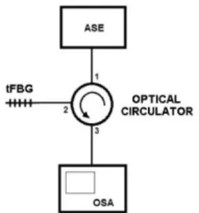
1566 nm. The interrogation was performed by an optical spectrum analyzer (OSA) Yokogawa
AQ6375, ASE and optical circulator, as setup shown in Fig. 2.
Fig. 2 - Optical circuit used to interrogate tapers with ASE, OSA and optical circulator.
The phase masks used, Ibsen, had pitches of 1073.50 nm and 1058.9 nm, without chirp and are
optimized to 193 nm illumination. All tFBGs and FBG have a length of 3 mm and were written using
a repetition rate of 250 Hz, energy of 2.5 mJ pulse, exposure time 2 minutes. The gratings were
Brazilian Microwave and Optoelectronics Society-SBMO received 27 Sept 2018; for review 12 Nov 2018; accepted 20 Nov 2018
Brazilian Society of Electromagnetism-SBMag © 2018 SBMO/SBMag ISSN 2179-1074 1058.90 nm; in both cases the temperature is set and adjusted through a digital controller unit. For
efficient thermal coupling between the Peltier thermoelectric pellet and the sample fiber, a mineral oil
was used at the interface. After stabilization of the temperature at each step a spectral acquisition was
performed using the OSAs. The thermal sensitivities were determined the peak wavelength values
(≈λB) of the spectra reflected by the FBGs and the corresponding temperatures. A second order
polynomial fit was chosen to obtain the thermal coefficient of the function λB = f (T), because it results the smallest error for this type of sensor [12].
IV. RESULTS
Assuming that in the process of manufacturing the tapered fibers the proportions between the core
and the cladding diameters are kept, that nominally determines the diameters of respectively, 125 μm
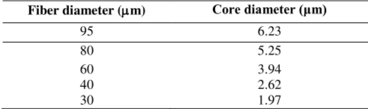
and 8.2 μm [13]. TABLE 1 shows the values of the core diameters for the different tapered fibers.
TABLE 1- ESTIMATION FOR CORE DIAMETERS IN THE DIFFERENT TAPERED FIBERS
Fiber diameter (m) Core diameter (μm)
95 6.23
80 5.25
60 3.94
40 2.62
30 1.97
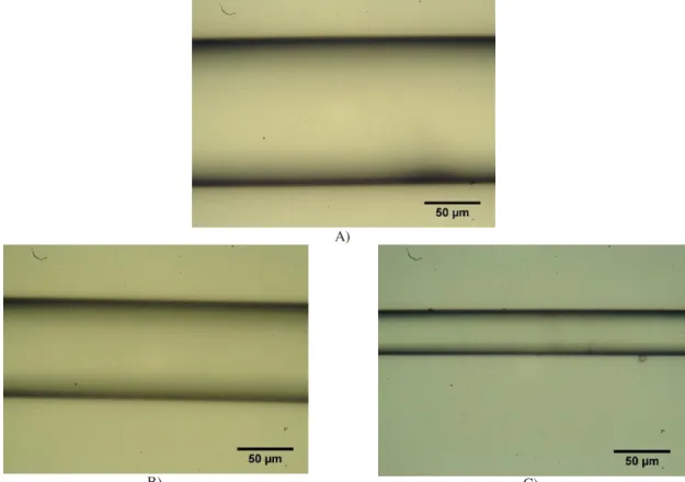
An OEM XSZ-N107CCD optical microscope with a 40X objective lens was used to obtain images
of FBG SM125, T80 and T40 tapers in the tuned region. Fig.3A) shows the optical fiber with regular
Brazilian Microwave and Optoelectronics Society-SBMO received 27 Sept 2018; for review 12 Nov 2018; accepted 20 Nov 2018
Brazilian Society of Electromagnetism-SBMag © 2018 SBMO/SBMag ISSN 2179-1074 A)
B) C)
Fig. 3 - Optical fibers diameters with A) 125 m; B) 80 m and C) 40 m (see text for details).
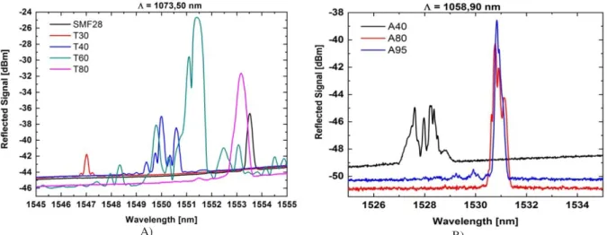
Fig. 4 A) shows the spectra of the various gratings in the tapered fibers written with pitch 1073.50
nm and the fiber with the original diameter (125 μm), at a temperature of 20 °C. There is an increase
of 12 dB in amplitude of the signal reflected by the grating on the tapered fiber down to 60 μm
diameter (T60) compared to the grating in the fiber with nominal diameter (SMF28). Such an increase
may be related to lower laser light attenuation through the thinner cladding during the inscription
process and the different signal amplitudes obtained in different tapers may be due to the writing
process, especially the critical condition for the beam alignment focusing on core of the optical fiber.
For the fibers with 40 (T40) and 30 (T30) μm diameters, the amplitudes of the reflected signals were
below that of the SMF28 grating, being5.2 dB, the largest difference presented, for a T30 tapered
fiber.
The relatively low signal reflected by the T30 and T40 gratings seems to be related to the smaller
fiber core used in the writing, which results in increased difficulty to reproduce the experimental
conditions when aligning& focusing the recording laser beam and also to a probable reduction of
concentration of germanium in the core.
Fig. 4 B) shows the spectrum of tapered fibers A40 (40 m), A80 (80 m) e A95 (95 m) written
with pitch 1058.9 nm, at 20 °C. There is a decrease of 6 dB in the amplitude of signal reflected
between the tapered fiber A95 and A40, and there is also a shift in B of 10.89 nm from A40 to
A95.The diameter with highest grating efficiency shown by results was T60 m with 21 dB of signal
Brazilian Microwave and Optoelectronics Society-SBMO received 27 Sept 2018; for review 12 Nov 2018; accepted 20 Nov 2018
Brazilian Society of Electromagnetism-SBMag © 2018 SBMO/SBMag ISSN 2179-1074
A) B)
Fig. 4 - Signals reflected by Bragg gratings in fibers with different diameters for two different spatial pitches (see text for details).
Still in Fig. 4, it’s seen a red shift in the Bragg wavelength, λB, as a function of the fiber diameter.
Such shift follows the effective refractive index behavior. Using equation (2) and the spectral
positions shown in Fig. 4, we obtain the changes in neff as a function of the fiber diameter, as shown in
the graphs on Fig. 3. The resulting values are neff= 1.447 for the fiber with its original diameter of 125 μm and 1.441 for the 30 μm tapered fiber, from the samples inscribed with 1073.50nm phase mask, whereas a slightly different set is obtained from the samples produced with the other phase-mask (Fig
5 B) is shown in TABLE 2, where the refractive index values are similar and the variations are
parameters dependent of the FBG recording process that is not fully controlled.
A) B)
Fig. 5–Evolution of effective refractive index (neff) in two sets ofproduced gratings as a function of the final fiber diameter.
TABLE 2- EFFECTIVE REFRACTIVE INDEX FOR DIFFERENT TAPERED FIBERS Grating Effective refractive index (neff)
T40 1.4438
A40 1.4432
T80 1.4468
Brazilian Microwave and Optoelectronics Society-SBMO received 27 Sept 2018; for review 12 Nov 2018; accepted 20 Nov 2018
Brazilian Society of Electromagnetism-SBMag © 2018 SBMO/SBMag ISSN 2179-1074 Fig.6A) shows the thermal sensitivity results for FBG written on the SMF28 fiber with original
diameter and three tFBGs recorded on fine tapered fibers, T30, T40 and T60. Fig. 6B) shows thermal
sensitivity results for three tFBGs recorded on fine tapered fibers A40, A80 and A95.
In TABLE3are shown the thermal sensitivities obtained for T30, T40, A40, T60, A80, A95tFBGs
and FBG SMF28. The mean sensitivity of the set is11.59 pm/°C and the largest deviation is +15.53%,
presented by the A95 sample.
A) B)
Fig. 6 - Thermal sensitivities in FBG in standard and tapered fibers, for two recording pitches.
T30 was characterized only up to 70 ° C due to the difficulty of observing the response due to the
small signal amplitude reflected in higher temperatures. The interaction of the evanescent field and
the change in the refractive index of the oil used at the interface between the fiber and the thermo
electric Peltier pellet could justify the amplitude drop in the reflected signal [14], but such a detailed
analysis is not the focus of this job.
TABLE 3- THERMAL SENSITIVITY IN DIFFERENT BRAGG GRATINGS
Grating Thermal sensitivity (pm/°C) Signal amplitude (dB)
SMF28 11.06 7.0
T30 09.65 2.0
T40 11.23 7.0
A40 13.21 4.0
T60 10.80 21.0
A80 11.79 10.0
A95 13.39 11.0
Mean 11.59 9.0
V. CONCLUSION
The production of fine-tuned fibers and the writing of the Bragg grating in these fibers greatly
expand the possibilities of applications for this type of fiber optic sensor. It is observed a reduction in
the effective refractive index (neff) in the obtained Bragg gratings, caused by the reduction in the
diameter of the used fibers. In terms of thermal sensitivity, it was not observed a significant change
for the produced gratings with different diameters. This is consistent with the thermal sensitivity
Brazilian Microwave and Optoelectronics Society-SBMO received 27 Sept 2018; for review 12 Nov 2018; accepted 20 Nov 2018
Brazilian Society of Electromagnetism-SBMag © 2018 SBMO/SBMag ISSN 2179-1074 [2] K.O. Hill, G. Meltz, “Fiber Bragg grating technology fundamentals and overview,” Journal of Lightwave and Technology, vol. 15, issue 8, p.1263-1276, 1997.
[3] L. Zhang, J. Lou and L. Tong, “Micro/Nanofiber Optical Sensors,” Photonic Sensors (2011) Vol. 1, No. 1: 31-42.
[4] X. Liu, T. Wang, Y. Wu, Y. Gong and Y.J. Rao, “Dual-Parameter Sensor Based on Tapered FBG Combined With Microfiber Cavity,” IEEE Photonic Technology Letters, Vol. 26, No. 8, 2014.
[5] A. S. Paterno, V. Oliveira and H. J. Kalinowski, “Automated Photosensitive Enhancement in Optical Fiber Tapers,” J. Microwaves, Optoeletronics and Eletromag. applications, vol. 10, No. 1, June 2011.
[6] J. L. Kou, M. Ding, J. Feng, Y. Q. Lu, F. Xu and G. Brambilla. “Microfiber based Bragg gratings for sensing applications: a review,” Sensors, vol.12, 2012.
[7] A. Felipe, G. Espindola, H.J. Kalinowski, J. A.S. Lima and A.S. Paterno, “Stepwise fabrication of arbitrary fiber optic tapers,” Optics Express, vol. 20. no. 18, 19893, 2012.
[8] A. D. Kersey, M. A. Davis, H. J. Patrick, M. Leblanc and K. P. Koo, “Fiber grating sensors,” Journal of Lightwave Technology, vol. 15, issue 8, p. 1442-1463, 1997.
[9] T. A. Birks, Y. W. Li, “The shape of fiber tapers,” Lightwave Technology, Journal of, v. 10, n. 4, p. 432-438, 1992.
[10] A. Othonos and X. Lee, “Novel and Improved Methods of Writing Bragg Gratings with Phase Masks,” Photonics Technology Letters, vol. 7, issue 10, 1995.
[11] F. Bilodeau, B. Malo, J. Albert, D. C. Johnson, K. O. Hill, Y. Hibino, M. Abe, and M. Kawachi, "Photosensitization of optical fiber and silica on silicon/silica waveguides," Opt. Lett., vol. 18, no. 12, pp. 953-955,1993.
[12] V. Oliveira, “Redes de Bragg para medições em altas temperaturas, “Tese de doutorado, Universidade tecnológica Federal do Paraná, 2012.
[13] Catalog Corning, access:http://ece466.groups.et.byu.net/notes/smf28.pdf.