Repositório ISCTE-IUL
Deposited in Repositório ISCTE-IUL:
2018-12-10Deposited version:
Post-printPeer-review status of attached file:
Peer-reviewedCitation for published item:
Naseri, P., Matos, S., Costa, J. R. & Fernandes, C. A. (2018). A fast computational algorithm to evaluate large transmit-arrays. In 12th European Conference on Antennas and Propagation, EuCAP 2018. London: Institution of Engineering and Technology.
Further information on publisher's website:
--Publisher's copyright statement:
This is the peer reviewed version of the following article: Naseri, P., Matos, S., Costa, J. R. & Fernandes, C. A. (2018). A fast computational algorithm to evaluate large transmit-arrays. In 12th European Conference on Antennas and Propagation, EuCAP 2018. London: Institution of Engineering and Technology.. This article may be used for non-commercial purposes in accordance with the Publisher's Terms and Conditions for self-archiving.
Use policy
Creative Commons CC BY 4.0
The full-text may be used and/or reproduced, and given to third parties in any format or medium, without prior permission or charge, for personal research or study, educational, or not-for-profit purposes provided that:
• a full bibliographic reference is made to the original source • a link is made to the metadata record in the Repository • the full-text is not changed in any way
The full-text must not be sold in any format or medium without the formal permission of the copyright holders.
Serviços de Informação e Documentação, Instituto Universitário de Lisboa (ISCTE-IUL) Av. das Forças Armadas, Edifício II, 1649-026 Lisboa Portugal
Phone: +(351) 217 903 024 | e-mail: administrador.repositorio@iscte-iul.pt https://repositorio.iscte-iul.pt
A Fast Computational Algorithm to Evaluate Large
Transmit-arrays
Parinaz Naseri
1, Sergio A. Matos
1,2, Jorge R. Costa
1,2, Carlos. A. Fernandes
11 Instituto de Telecomunicações, Instituto Superior Técnico, Universidade de Lisboa, Lisbon, Portugal, parinaz.naseri@lx.it.pt 2 Departamento de Ciências e Tecnologias da Informação, Instituto Universitário de Lisboa (ISCTE-IUL), Lisbon, Portugal
Abstract—Transmit-arrays (TAs) have become popular
solutions for point-to-point communications due to their low-profile and high-efficiency. However, simulation of these large and detailed structures demands a great amount of memory and time. Here, we propose a fast algorithm to estimate the performance of a beam-steering TA to accelerate its design optimization process. The results and the required resources of the algorithm are compared with the ones of Ansys HFSS. It is shown that this algorithm can fairly evaluate the key factors of the performance of a TA within couple of minutes with memory resource of only 1 GB.
Index Terms–Array antenna, trasnmit-arrays,
reflect-arrays, computational method.
I. INTRODUCTION
Passive transmit-arrays (TA) and reflect-arrays (RA) are very attractive solutions as gain enhancers in point-to-point and satellite communications [1]. These planar structures are usually populated with large number of unit-cells with dimensions smaller than the wavelength. The number of unit-cells and the details of each unit-cell directly impact the amount of resources required to simulate such arrays. As a result, full wave simulations of high-gain planar arrays might take days even with high-performance computers.
Optimizing the design of these arrays and evaluating their performances before prototyping make their simulations an essential part of their design. However, these simulations can require a great amount of memory and time, which makes the optimization process time-consuming or even impossible based on the available resources. Therefore, a faster reliable technique rather than the full-wave simulation is necessary for this step. As a result, several methods have been proposed for RAs [8]-[12] and TAs [13]. Authors in [13] briefly describe a method to estimate only the main beam of a fixed-beam TA.
The literature yet lacks a general fast algorithm to evaluate both the main beam and the cross-polarization level. Here, we propose a general fast algorithm suited for TAs and/or RAs composed of any kind of unit-cells with even complicated shapes. These unit-cells are different in their geometries and in the incidence angles they receive the signal from the feed antenna. Based on the unit-cells’ working principle, they can be categorized into two main groups: phase delay (PD) and phase rotation (PR). A set of PD cells includes a discrete number of cells with slightly different geometries, all with good transmission coefficient, in TA case, but slightly
different phases shifts [2]-[5]. In the case of the PR cells, only one geometry for the PR cell is designed and then the cell is rotated by any angle from 0º to 180º to provide a continuous phase shift between 0º to 360º [6]-[9].
This case is important for various reasons including the fact that the scattered fields are at both sides of the TA and not just the primary feed side as in RAs. Secondly, the composing unit-cells have details much smaller than the wavelength that makes their simulation even more time and memory consuming.
II. DESCRIPTION OF THE ALGORITHM
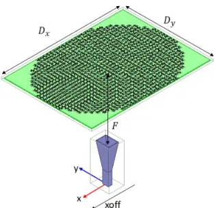
To introduce the algorithm, we consider a TA similar to the one in [2] operating at 30GHz, with a rectangular aperture of size Dy=140mm × Dx=190mm, see Fig. 1. The size of the
aperture is chosen to maximize the aperture efficiency for steering the beam from 15º to 50º zenith angles by in-plane shifting the feed from = +30 to −27 in Fig. 1. By in-plane rotation of the TA, 360º azimuth scanning can be obtained. The phase law of the TA is based on (1) where is the wavenumber at the design frequnecy and focal distance (F) is 100mm and the TA directs the beam to α0=32.5º when the feed is at the focal position of the TA. This α0 is one of the design parameters of a beam-steering TA that can be optimized based on desired scanning range [2]. The TA is fed with standard 14.5dBi gain Ka-band rectangular horn with linear polarization. The performance of the TA is evaluated for both orthogonal linear polarizations by 90º rotation of the horn. Then the results are post-processed to be obtain the response of the TA to a synthesized circularly-polarized incident wave. Fig. 1 shows the configuration of the whole structure with the x-polarized horn antenna.
Fig. 1 The configuration of the TA in front of the x-polarized horn antenna.
We populate the TA with the unit-cell similar to the one in [6]. The three metallic layers of the cell are separated by 0.508mm-thick RT Duroid 5880 (εr=2.2 and tanδ=0.0009). The exact dimensions of the unit-cell are presented in [14]. By rotating this unit-cell from 0º to 180º, it is possible to achieve up to 360º continuous phase shift in the transmitted wave, see Fig. 2. After populating the TA, it functions as shown schematically in Fig. 3. It collimates the orthogonal circular polarization of the feed antenna while it does not influence the cross-polarization component. Therefore, one component in the transmission is a high-gain plane-wave in the far-field while the other has a spherical phase front. The reverse stands true for reflections, see Fig. 3.
Fig. 2 The transmit-array unit-cell that provides phase shift from 0º to 360º by its rotation up to 180º.
Fig. 3 The behavior of the transmit-array and the scattered waves.
The amount of rotation angle of each cell and the incidence angle at which it receives the wave from the feed determines the cell scattering parameters (S-parameters). The incidence angle that different cells receive on the surface of the TA is depicted in Fig. 4. Therefore, the composing unit-cells of this TA can be categorized based on their rotation angle and incidence angle at their surface.
Fig. 4 The incident angles from the feed positioned at the center of the TA and at focal distance of F=100mm across the surface of the TA in Fig. 1. Each pixel represents one unit-cell.
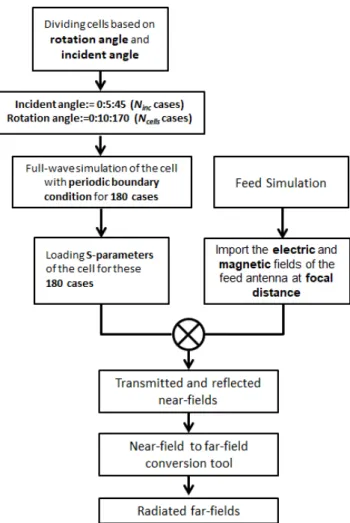
As the first step of the algorithm, we fit all the composing unit-cells into cases where the incidence angle changes (in this case) between 0º and maximum incidence angle on the TA, i.e. 45º, with 5º step (Ninc =10) and the rotation angle
changing between 0º and 170º with 10º step (Ncells =18). The
steps for these categories can be finer but the mentioned steps gave sufficient accuracy. This leads to Ninc×Ncells=180
different unit-cell simulations. The maximum amount of oblique incidence, here 45º, is obviously less for TAs with higher F/D.
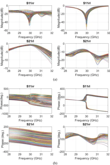
Afterwards, we simulate the unit-cell for these 180 cases with periodic boundary condition and Floquet mode excitation in CST Microwave Studio [15], which can be done in any other full-wave solver. We then export all the S-parameters of the unit-cell for the 180 cases. This step is required only once for any type of unit-cell, and the obtained data base can be employed for different sizes of arrays and different positions of the feed antenna. Fig. 5 shows the magnitude and phase of the circular polarization S-parameters of the unit-cells populating the TA in Fig. 1 for different incident angles and different rotation angles.
(a)
(b)
Fig. 5 (a) Magnitude and (b) phase of the circular S-parameters of the unit-cells rotated by different angles and excited by different incident angles on the TA in Fig. 1.
The second part of the proposed algorithm requires both the electric and magnetic fields of the primary feed at the focal distance of the TA. This can be exported from a full-wave simulation of the primary feed in any full-full-wave solver, calculated at the center of each cell. Afterwards, the tangential components of the scattered electric and magnetic waves can be obtained by multiplying the circular polarization S-parameters of the cells by the input electric and magnetic fields as in (2) and (3) respectively,
(2)
(3)
where er, el, hr, and hl are respectively the electric RHCP,
electric LHCP, magnetic RHCP, and magnetic LHCP fields from the primary feed on the TA. Finally, the elements of Es
and Hs represent the transmitted and reflected RHCP and
LHCP waves from the TA that provide the near-fields to calculate the far-field patterns. Fig. 6 shows the magnitdue and phase of the reflected and transmitted circular near-fields at the bottom and top surfaces of the TA, respectively.
(b)
Fig. 6 (a) Magnitude and (b) phase of the transmitted and reflected RHCP and LHCP electric near-fields at from the bottom and top surfaces of the TA for central position of the RHCP feed.
By calculating the electric and magnetic fields seperately based on (2) and (3), we avoid making a plane-wave approximation for the whole surface of the TA. Here, we only consider the plane wave approximation for each unit-cell. As can be seen from Fig. 6 (b), only the transmitted LHCP and the reflected RHCP fields have a planar phase front while the transmitted RHCP and the reflected LHCP fields have spherical phase fronts. It is noted that although we simulate the unit-cell with different rotation and incidence angles, we yet apply periodic boundary conditions in the unit-cell simulation that indicates the cell is surrounded by similar cells, which is not true in a beam-collimating TA.
As the last step of this method, the near-field data of the electric and magnetic fields are imported into our customized software [18] to calculate the far-field patterns. Any other
method that can calculate the far-field patterns from the near-field source can be employed at this step. Fig. 7 summarizes the steps of this algorithm.
Fig. 7 Algorithm to obtain far-field patterns of large transmit-arrays in Figure 3.
III. COMPARISON BETWEEN ALGORITHM AND FULL
-WAVE SIMULATION
Here, we analyzed the introduced TA for three positions of the feed to steer the beam both by the proposed algorithm and Ansys HFSS [16]. It is worth mentioning that hybrid finite element boundary integral (FE-BI) method available by Ansys HFSS is employed in all full-wave simulations of this section in order to reduce the required time and memory [17]. The feed is placed at xoff= +30mm, 0mm, and -27mm, see Fig.
1. By mechanically shifting the feed to these positions, the beam based on (1) is directed at α0= 15º, 32º, and 50º, respectively.
In Fig. 8 (a), it is shown that both the full-wave simulation in HFSS and the proposed algorithm present similar beam direction and beam-width at each position of the feed. The maximum difference between the gain calculated by HFSS and by the new algorithm occurs for the beam directed at α0= 15º, which is 1.5dBi, while this difference reduces to 0.1dBi for the beam directed at α0= 50º. Moreover, the scan loss over
this scan range is 4.1dBi calculated by the algorithm which is only 1.4dBi more than the one obtained by HFSS.
Fig. 8 (b) presents the far-field patterns of the cross-polarization component using both tools. As expected and explained earlier, this TA has no phase correcting effect on the cross polarization component, and consequently the cross polarization far-field is not pointed at the main beam direction and has a maximum in vicinity of θ=0º. Fig. 8 (b) shows that the proposed algorithm correctly estimates the overall shape of the cross component patterns although the cross polarization gain calculated by it is 3.4dBi higher than the one obtained with HFSS.
Fig. 8 Far-field patterns of the TA using full-wave simulation in Ansys HFSS [16] and using the algorithm.
The comparison with full wave Ansys HFSS calculations proves that the proposed algorithm can correctly estimate the overall performance of a large TA. Therefore, one can easily use this tool at the beginning of a design process to determine the general parameters of a TA such as F/D, Dx and Dy in case of a rectangular aperture, and α0. It allows fast estimation of main beam direction, beam-width, gain of the TA as well as cross polarization level and scanning loss. Furthermore, this algorithm provides a way for a designer to gain confidence in her/his design before simulating the whole structure using an
accurate but time-consuming full-wave simulation software. As a result, the full-wave simulation can be done only once as the last step before moving to prototyping. Table I compares for the discussed TA the resources such as time and memory required for the simulation of each polarization and position of the feed using HFSS and the proposed algorithm.
TABLE I
COMPARISON BETWEEN REQUIRED RESOURCES FOR HFSS AND THE
ALGORITHM
Tool Time Memory
Ansys HFSS 17h 108 GB
Proposed Algorithm 2m 10s 1 GB
IV. CONCLUSION
A fast algorithm is presented to estimate the key performance characteristics of a beam-steering transmit-array such as the main beam direction, beam-width, gain, cross polarization level, and scan loss. It was shown that this algorithm can be employed even for non-collimating TAs where the scattered field does not have a planar phase front. The accuracy and the required resources of the algorithm are compared to a full-wave simulation software, i.e. HFSS. It is proved that, after a one-time full-wave analysis of a finite set of individual cells with different incidence angles, the proposed algorithm can expedite the optimization of large planar arrays before prototyping. A 500× factor was obtained for the presented example. Last but not the least, this algorithm can also be used for other types of transmit-array cells such as PD cells in [2]-[5] as well as reflect-arrays cells.
REFERENCES
[1] S. V. Hum and J. Perruisseau-Carrier, “Reconfigurable reflectarrays and array lenses for dynamic antenna beam control: A review,” IEEE
Trans. Antennas Propag., vol. 62, no. 1, pp. 183–198, Jan. 2014.
[2] E. B. Lima, S. A. Matos, J. R. Costa, C. A. Fernandes, and N. J. G. Fonseca, “Circular polarization wide-angle beam steering at Ka-band by in-plane translation of a plane lens antenna,” IEEE Trans. Antennas
Propag., vol. 63, no. 12, pp. 5443-5455, Dec. 2015.
[3] S. A. Matos, E. B. Lima, J. S. Silva, Jorge R. Costa, C.A. Fernandes, N. J. G. Fonseca, J. R. Mosig, “High gain dual-band beam steering transmitarray for satcom terminals at Ka band,” IEEE Trans. Antennas
Propag., vol. 65, no. 7, pp. 3528 - 3539, Jul. 2017.
[4] M. Li, M. A. Al-Joumayly, N. Behdad, "Broadband true-time-delay microwave lenses based on miniaturized element frequency selective surfaces", IEEE Trans. Antennas Propag., vol. 61, no. 3, pp. 1166-1179, Mar. 2012.
[5] N. Cagnon and A. Petosa, “Using rotatable planar phase shifting surfaces to steer a high-gain beam,” IEEE Trans. Antennas Propag., vol. 61, no. 6, pp. 3086-3092, Jun. 2013.
[6] P. Naseri, R. Mirzavand, and P. Mousavi, “Dual-band circularly polarized transmit-array unit-cell at X and K bands,” in Proc. 10th Eur. Conf. Antennas Propag. (EuCAP), Davos, Switzerland, Apr. 2016, pp. 1–4.
[7] P. Naseri, F. Khosravi, and P. Mousavi, “Antenna-filter-antenna-based transmit-array for circular polarization application,” IEEE Antennas
Wireless Propag. Lett., vol. 16, pp. 1389 - 1392, 2017.
[8] R. H. Philion and M. Okoniewski, “Lenses for circular polarization using planar arrays of rotated passive elements,” IEEE Trans. Antennas
Propag., vol. 59, no. 4, pp. 1217-1227, Apr. 2011.
[9] L. D. Plama, A. Clemente, L. Dussopt, R. Sauleau, P. Potier, and Ph. Pouliguen, “Circularly polarized transmit-array with sequential rotation in Ka-band,” IEEE Trans. Antennas Propag., vol. 63, no. 11, pp. 5118-5124, 2015.
[10] F. Venneri, S. Costanzo, G. Di Massa, and G. Angiulli, “An improved synthesis algorithm for reflectarrays design,” IEEE Antennas Wireless
Propag. Lett., vol. 4, pp. 258 - 261, 2005.
[11] Y. Abdallah, C. Menudier, M. Thevenot, and T. Monediere, “Reflectarray antennas with accurate calculation of phase shifts,” in proceedings of European Conference on Antennas and Porpagation (EuCAP), Rome, Italy, Apr. 2011.
[12] Daniel R. Prado, Manuel Arrebola, Marcos R. Pino, and Fernando Las-Heras, “Complex reflection coefficient synthesis applied to dual-polarized reflectarrays with cross-polar requirements,” IEEE Trans.
Antennas Propag., vol. 63, no. 9, pp. 3897-3907, Sep. 2015.
[13] R. H. Philion and M. Okoniewski, “Lenses for circular polarization using planar arrays of rotated passive elements,” IEEE Trans. Antennas
Propag., vol. 59, no. 4, pp. 1217-1227, Apr. 2011.
[14] P. Naseri, S. A. Matos, J. R. Costa, and C. A. Fernandes, “Phase delay vs phase rotation cells for circular polarization transmit-arrays ‒ application to satellite Ka-band beam steering,” IEEE Trans. Antennas
Propag., vol. 66, no. 2, 2018, in press.
[15] CST Microwave Studio. [2014, Oct.]. Computer Simulation Technology [Online]. Available: http://www.cst.com
[16] ANSYS® High Frequency Electromagnetic Field Simulation, Release 18.0: http://www.ansys.com.
[17] John Silvestro, “Hybrid finite element boundary integral method,” Ansys, Inc. [online]. Available: https://support.ansys.com
[18] E. Lima, J. Costa, M. Silveirinha, and C. Fernandes, “ILASH - Software tool for the design of integrated lens antennas” IEEE Antennas and Propagation Society International Symposium (AP-S 2008), pp. 1–4, 2008.