Brazilian Microwave and Optoelectronics Society-SBMO received 2 June 2018; for review 21 June 2018; accepted 31 Oct 2018 Brazilian Society of Electromagnetism-SBMag © 2018 SBMO/SBMag ISSN 2179-1074
Abstract— Direction of arrival algorithms are used, in general, to estimate a number of incident plane waves on the antenna array and their angles of incidence. In this paper, firstly, a new approach representing a more extensive version of the conventional Capon method is proposed. The study employs the root-Capon approach based on cross-correlation matrix in extracting the estimated direction-of-arrival of some number of signals to a given uniform linear array (ULA) antenna system. Secondly, a simple modification on the antenna element’s number is employed for the Capon and the proposed approach to obtain more performances. The effectiveness of the proposed algorithm is verified through numerical simulation examples, and it is shown that the root version of Capon method can provide more accurate angle estimation with less computational complexity than conventional Capon algorithm. Similarly, it is found also that the used modification plays a significant role in the performance’s improvement of Capon and its variant approaches.
Index Terms—Direction of arrival estimation, array signal processing, spatial spectrum (pseudo-spectrum), Capon, root-Capon, improved-root-Capon.
I. INTRODUCTION
Smart Antenna system combines multiple antenna elements with a signal processing capability to optimize its radiation pattern automatically in response to the signal environment. Furthermore, in reality antennas are not smarts, it is the digital signal processing along with the antennas that plays a key role to make the system smart. In this kind of antenna array, angle-of-arrival (AOA) estimation and beam-forming are the two main functions that can be carried out, thanks to integrated techniques on sophisticated signal processing. This means that the estimation of the signal direction is the most important signal processing step in smart antennas. In these last, direction of arrival (DOA) algorithms are used, in general, to estimate a number of incident plane waves on the antenna array and their angles of incidence; moreover, DOA estimation is considered as critical technology of array signal processing and it does not lie only to smart antennas but, it is also of great importance in a variety of applications, such as radar, speech signal processing, sonar, astronomy, electronic
Improved Polynomial Rooting of Capon’s
Algorithm to Estimate the
Direction-of-Arrival in Smart Array Antenna
Aounallah Naceur
Department of Electronic and Telecommunications, Faculty of new information technologies and communication, Kasdi Merbah University, Ouargla 30000, Algeria
Brazilian Microwave and Optoelectronics Society-SBMO received 2 June 2018; for review 21 June 2018; accepted 31 Oct 2018 Brazilian Society of Electromagnetism-SBMag © 2018 SBMO/SBMag ISSN 2179-1074
surveillance, wireless communication, medical diagnosis and treatment, seismology and other areas [1]-[3].
Many algorithms for DOA estimation have been proposed, and their performances have been studied thoroughly over the years; besides, intensive studies on DOA estimation field were carried out to pinpoint the most suitable algorithm for the application of interest. The most widely used and most popular are: Bartlett method [4], Capon method [5], the maximum entropy method [6], Multiple Signal Classification (MUSIC) [7], the minimum norm technique [1], and Estimation of Signal Parameters via Rotational Invariance Techniques (ESPRIT) [8] etc. Generally, the DOA estimation techniques can be classified into two main categories: beam-scan approaches and subspace approaches [9]-[10]. The beam-scan techniques form a conventional beam, scans it over the appropriate region and plots the magnitude squared of output. While in subspace techniques which are also referred to as high-resolution algorithms, the orthogonality between the signal and noise subspaces is exploited [10].
Capon approach has been one among many well known algorithms for the angle of arrival (AOA) determination of incident signals using array antenna structure. Since its appearance, the standard Capon algorithm saw some improvements where several modifications were proposed and numerous researches were done in this topic. In [11], a cascaded Capon beamformer termed as m-Capon was proposed so as to avoid exact EVD and sources number estimation. New modified Capon estimator called MCB was proposed for estimating the direction-of-arrivals (DOAs) of multiple noncoherent narrowband signals [12]. George, in his work [13], has derived matched filter-bank-based spectral estimators which are the amplitude spectrum Capon (ASC) and the power spectrum Capon (PSC) estimators. These estimation methods have provided spectra which are characterized by a significantly improved resolution compared to classical approaches. Also the minimum variance distortionless response (MVDR) which is a data-dependent algorithm proposed by Capon was modified in [14] for reducing direction-of-arrival estimation mismatch. The paper objectives are to design and model a new technique in order to overcome the signal suppression phenomena with respect to any deflection in the signature vector and to increase the behaviour freedom degree by reducing the Vandermonde matrix effects. In [15], the authors have used the Levenberg-Marquardt (LM) algorithm to the optimization of the cost function of the Capon for azimuth/elevation angle-of-arrival (AOA) estimation. In the same context, there have been other studies on applying the Newton-type method to the optimization mentioned by Selva [16].
Brazilian Microwave and Optoelectronics Society-SBMO received 2 June 2018; for review 21 June 2018; accepted 31 Oct 2018 Brazilian Society of Electromagnetism-SBMag © 2018 SBMO/SBMag ISSN 2179-1074
propose a new modification related to the antenna parameters. This proposition leads to improve the Capon method performances in term of resolution, and to obtain more best and accurate numerical results by the root-Capon algorithm.
The remainder of this paper is organized as follows: the signal model is presented in section II. A summary of the conventional Capon algorithm, the proposed polynomial version method, and the modified number of elements are introduced in section III. Section IV provides the simulation results and finally, our conclusion is given in section V.
II. SIGNALMODEL
The problem of central interest herein is that of the angles of arrival estimation which can be stated in the following way:
A uniform linear array (ULA) composed of 𝑁 antenna elements receives transmitted signals from
𝑀 far-field sources (M < N). The objective is then to isolate the 𝑀 unknown sources by exploiting the signals which are received by the array antennas and the available information’s in reception. The waves which are transmitted by the sources arrive on the array from various directions (𝜃 , … , 𝜃 ). The received signals are, therefore, linear combinations of the incident signals and noise. By carrying out 𝐾 observations based on the number of snapshots, the 𝑘 received vector at the antennas array output 𝑥(𝑘) ∈ ℂ × can be modeled as [9],[11]:
𝒙(𝑘) = 𝑨(𝜃). 𝒔(𝑘) + 𝒗(𝑘), 𝑘 = 1, ⋯ , 𝐾
(1)
Equation (1) can be written in a matrix form as follows:
𝒙(𝑘) = [𝒂(𝜃 ), 𝒂(𝜃 ), … , 𝒂(𝜃 )].
⎣ ⎢ ⎢ ⎢ ⎡𝑠𝑠 (𝑘)(𝑘)
𝑠 (𝑘) ⋮ 𝑠 (𝑘)⎦⎥
⎥ ⎥ ⎤
+ 𝒗(𝑘)
(2) Where 𝒔(𝑘) is the [𝑀 × 1] complex transmit vector, 𝑨(𝜃) is the [𝑁 × 𝑀] steering matrix of the sources, it contains information about the angles of arrival, and 𝒂(𝜃 ) = 𝑒 , ,
𝑒 , … , 𝑒 , is the [𝑁 × 1] steering vector which is related to the 𝑚 source with 𝜙 , =
(𝑛 − 1)𝑠𝑖𝑛𝜃 represents the geometrical phase shift introduced by the 𝑛 array element to the
𝑚 source according to the angle of incidence. (. ) denotes the transposition, 𝑑 and λ are the inter-antenna distance and the wavelength, respectively. 𝒗(𝑘) is the [𝑁 × 1] additive white Gaussian noise (AWGN) vector with zero-mean and variance 𝜎².
Brazilian Microwave and Optoelectronics Society-SBMO received 2 June 2018; for review 21 June 2018; accepted 31 Oct 2018 Brazilian Society of Electromagnetism-SBMag © 2018 SBMO/SBMag ISSN 2179-1074
𝑹𝒙𝒙= 𝐸[𝒙(𝑘)𝒙 (𝑘)]
(3) Where (. ) indicates the Hermitian transpose.
The estimated spatial correlation matrix 𝑹 for the 𝐾 number of snapshots is given by:
𝑹 =𝐾1 𝒙(𝑘)𝒙 (𝑘)
(4) Since the covariance matrix 𝑹 is estimated, several methods can be used for the direction of arrival estimation. These various methods were largely studied in the literature of smart antennas and spectral analysis.
III. DIRECTIONOFARRIVALALGORITHMS
In this section, it is worth to call back briefly the traditional Capon’s algorithm, then explain in detail the proposed polynomial algorithm, and finally clear up the modification which can be applied to the two algorithms.
A. Capon algorithm
Introduced by J. Capon [5] and also called Minimum Variance Distortionless Response (MVDR) algorithm. This spectral-based method is one of the conventional popular techniques. The main idea of Capon’s minimum variance algorithm is to minimize the received power of the incoming signal in all direction while maintaining a unity gain in look direction [17]-[18]. The constrained imposed on this algorithm is given as:
𝑚𝑖𝑛 𝐸[|𝒚(𝑡)| ] = 𝑚𝑖𝑛 𝝎 𝑹 𝝎
Subject to
𝝎 𝒂(𝜃 ) = 1
(5) Solving this constraint optimization problem by the use of Lagrange optimization technique for the weight vector [2], [19] we obtain the Capon’s weight vector:
𝝎 = 𝑹 𝒂(𝜃)
𝒂(𝜃) 𝑹 𝒂(𝜃)
(6) Thus, Capon’s output spectrum is:
𝑃 (𝜃) =𝒂(𝜃) 𝑹 𝒂(𝜃)1
Brazilian Microwave and Optoelectronics Society-SBMO received 2 June 2018; for review 21 June 2018; accepted 31 Oct 2018 Brazilian Society of Electromagnetism-SBMag © 2018 SBMO/SBMag ISSN 2179-1074
scanning angles and determine the direction of arrival by locating the peaks in the spectrum. The estimated values of direction of arrival of all signals can be obtained by:
𝜃 = 𝑎𝑟𝑔 𝑚𝑎𝑥 𝑃 (𝜃 ), 𝑚 = 1,2, ⋯ , 𝑀
(8)
B. Proposed Algorithm
The method proposed here is called root-Capon, as its name shown, is a polynomial-rooting version of the classical Capon algorithm. Furthermore, similar direction of arrival estimation method based on the spectral Capon rooting algorithm is developed in a slightly different way by [20]. This real polynomial rooting technique uses a form of derivation on the denominator of the Capon’s spectrum expression and some manipulations, and then it carries out a conformal transformation which maps the unit circle onto the real line, to find the polynomial roots. Otherwise, our key idea is the same as that of root-MUSIC [21]. This means that, to write the denominator of the capon spectrum expression which is named the null spectrum as a polynomial and then find the roots of the polynomial.
Starting with the Capon’s spectrum expression:
𝑃 (𝜃) = 1
𝒂(𝜃) 𝑹 𝒂(𝜃)
(9) Defining 𝐷(𝜃) = 𝒂(𝜃) 𝑹 𝒂(𝜃) as the null spectrum, then the denominator of equation (9) above can be rewritten as:
𝑃 (𝜃) =𝐷(𝜃)1
(10) In the case of a ULA, the 𝑛 element of the array steering vector is given by:
𝒂 (𝜃) = 𝑒 , 𝑛 = 0, 1, ⋯ , 𝑁 − 1
(11) That means, the null spectrum 𝐷(𝜃) can be rewritten as:
𝐷(𝜃) = 𝑒 𝐷 𝑒
(12)
Letting 𝑧 = 𝑒 , the denominator 𝐷(𝜃) can be became:
Brazilian Microwave and Optoelectronics Society-SBMO received 2 June 2018; for review 21 June 2018; accepted 31 Oct 2018 Brazilian Society of Electromagnetism-SBMag © 2018 SBMO/SBMag ISSN 2179-1074
= 𝐷 𝑧
(13) With 𝐷 denotes the 𝑚 row and 𝑛 column element of 𝑹
Letting now 𝑙 = 𝑛 − 𝑚 to simplify the double summation of equation (13) to a single one. The range on 𝑙 is set by the limits on 𝑛 and 𝑚, i.e. – (𝑁 − 1) ≤ 𝑙 ≤ (𝑁 − 1). Then, the polynomial 𝐷(𝑧)
can be written as:
𝐷(𝑧) = 𝐷 𝑧
(14) Where 𝐷 is the sum of the elements along the 𝑙 diagonal such that:
𝐷 = 𝐷𝑚𝑛
𝑛−𝑚=𝑙
(15) Root-Capon solves the rooting problem of a polynomial rather than finding the spectral peaks in the Capon algorithm. Additionally, the roots of the polynomial 𝐷(𝑧) that lie closest to the unit circle becomes equivalent to the poles of the Capon’s pseudo-spectrum. That is 𝑃 (𝑧) ( ) =
𝑃 (𝜃) with (𝜃) = −2𝜋 𝑠𝑖𝑛 𝜃 .
The polynomial of equation (14) is of order 2(𝑁–1) and thus their roots can be written as follows:
𝒛 = |𝑧 |𝑒 . ( ), 𝑖 = 1, 2, ⋯ , 2(𝑁 − 1)
(16) Where 𝑎𝑟𝑔(𝒛 ) is the phase angle of 𝒛.
The roots lying close to the unit circle have magnitudes |𝑧 | ≃ 1. One can calculate and find the
DOA basing on the relationship between 𝑧 and 𝜃 , (𝑒 . ( ) and 𝑒 𝜽), which gives:
𝜽 = −𝑠𝑖𝑛 2𝜋𝑑 . 𝑎𝑟𝑔 (𝒛 )𝜆
(17)
C. Modified Number of Array Elements
Brazilian Microwave and Optoelectronics Society-SBMO received 2 June 2018; for review 21 June 2018; accepted 31 Oct 2018 Brazilian Society of Electromagnetism-SBMag © 2018 SBMO/SBMag ISSN 2179-1074
resolution performance of Min-Norm and Root-Min-Norm algorithms.
In order to make the peaks of the Capon spectrum sharper or to reach less error in root-Capon algorithm, one of the best solutions is to increase the number of antennas. This is realizable, not only by increasing the array size but also, by the modification of the real array element’s number by multiplying it with a multiplicative factor (𝑀𝐹). The new number of array elements 𝑁′ can then be written as:
𝑁′ = 𝑁 × 𝑀𝐹
(18) The new elements number, referred by equation (18), can be easily substituted in the improved Capon and root-Capon approaches. This new number of antenna array elements is of outstanding importance during the signal processing stage of the array system. Indeed, the multiplicative factor gives a number of elements offering more signal component for the followed algorithm. In addition, the selection of a suitable multiplicative factor easily leads to determine the actual and appropriate number of elements that can be required for the design of the antenna array.
IV. SIMULATIONRESULTS
In this section, we work on the improvement of the performances of the capon and its rooting version where we make a simple modification by using a multiplicative factor related to the number of array elements. The direction of arrival performances of the studied methods can be demonstrated and evaluated by using a computer simulation programs that we have developed on Matlab software.
In the initial simulations, we consider an eight-element uniform linear array. Three far-field signals (𝑀=3) impinge initially on the antenna array from directions of −5°, 10°, and 25◦, respectively. Assume that the ratio between the wavelength and the inter-element spacing 𝑑 is 2. The noise is characterized as additive, white and Gaussian distributed with zero mean and variance 𝜎² =0.1. The number of snapshot is 𝐾 = 200.
It should be to note also that some previous declared parameters will be changed in order to study other simulation scenarios, but the following assumptions are usually made:
The antennas noise is uncorrelated with the signals.
The number of sources is known and is less than the number of antennas.
There is no correlation between sources.
Brazilian Microwave and Optoelectronics Society-SBMO received 2 June 2018; for review 21 June 2018; accepted 31 Oct 2018 Brazilian Society of Electromagnetism-SBMag © 2018 SBMO/SBMag ISSN 2179-1074
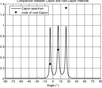
Fig. 1. Normalized Capon spectrum and roots found with root-Capon.
Additionally, the roots of the root-Capon polynomial are displayed in the complex plane, together with the unit circle, that allows us to visualize the effectiveness of this method in estimating the angles of arrival (Fig. 2). The angle of arrival of the sources is obtained from the phase of the roots whose magnitude is closed to 1. There are 3 roots having magnitude very close to 1 and corresponding to the 3 simulated sources.
Fig. 2. Angle of arrival estimation with root-Capon method.
-90 -75 -60 -45 -30 -15 0 15 30 45 60 75 90
0 0.2 0.4 0.6 0.8 1 1.2 1.4
Angle (°)
Comparison between Capon and root-Capon methods
Capon spectrum roots of root-Capon
-1.5 -1 -0.5 0 0.5 1 1.5
-1.5 -1 -0.5 0 0.5 1 1.5
Real part
Im
ag
in
ar
y
pa
rt
root-Capon method
Brazilian Microwave and Optoelectronics Society-SBMO received 2 June 2018; for review 21 June 2018; accepted 31 Oct 2018 Brazilian Society of Electromagnetism-SBMag © 2018 SBMO/SBMag ISSN 2179-1074
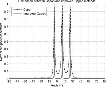
It is clearly shown from Fig. 3 that the two used spectral methods are able to find the directions of the three sources corresponding to -5, 10, and 25, but with different estimation precisions that depend on the width of the peaks. The performances in term of angle of arrival estimation of the proposed modified-Capon algorithm are gradually improved with a multiplicative factor 𝑀𝐹=3. This last realizes exactly an increase in the number of antennas. Thus, multiplying the number of antennas leads to widen the array, and this leads to improve the angle of arrival estimation performance because multiple antennas provide the diversity gain.
Fig. 3. Comparison between Capon and improved-Capon pseudo-spectrums.
Brazilian Microwave and Optoelectronics Society-SBMO received 2 June 2018; for review 21 June 2018; accepted 31 Oct 2018 Brazilian Society of Electromagnetism-SBMag © 2018 SBMO/SBMag ISSN 2179-1074
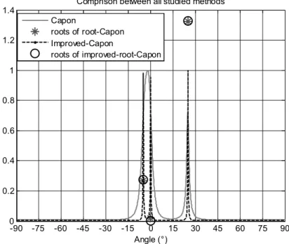
Fig. 4. Comparison between the studied algorithms when the DOAs are -5°, 0°, and 25°.
The polynomial versions offer good performances and smaller computational complexity than the pseudo-spectrum versions. The two polynomial algorithms are able to distinguish between two close signals while the classical Capon method failed to differentiate between them. In addition, the estimation error decreases if the separation between signals increases.
The complexity of the required operations in the scanning angle process stage to construct the spatial spectrum of the standard Capon method is 𝑀(𝑁 + 𝑁) for the number of multiplications and
𝑀(𝑁 + 1)for the number of additions, where 𝑀 is the number of angles to scan and 𝑁 is the number of antenna elements. The computational complexity of the improved-Capon slightly exceeds that of the standard Capon, and precisely in the multiplication operations which are 𝑀(𝑁 + 𝑁 + 1). The two rooting polynomial methods, that are developed in our work, are proposed to reduce the computation complexity of their original algorithm versions. Then, the Improved-root-Capon method can be evaluated as efficient computationally.
In order to compare the effectiveness and estimation performance in terms of mean square error (MSE) of the proposed polynomial method “root-Capon” with its enhanced version “Improved-root-Capon”, the application of the two methods in different simulation scenarios allows us to present the results mentioned in tables (I, II and III).
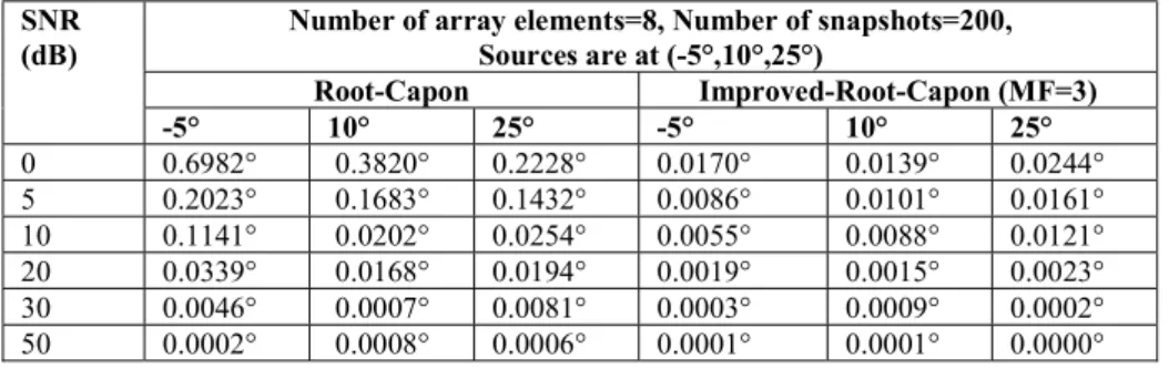
In the simulation scenario of Table I, we assume the number of snapshots is fixed to 200 for three different signals arriving on ULA from different directions. This simulation compares the variations in performance of our two AOA rooting methods with a variation of signal-to-noise ratio (SNR). The MSE is calculated for each SNR and enrolled for our algorithms in Table I. The performance
-90 -75 -60 -45 -30 -15 0 15 30 45 60 75 90
0 0.2 0.4 0.6 0.8 1 1.2 1.4
Angle (°)
Comprison between all studied methods Capon
roots of root-Capon Improved-Capon
Brazilian Microwave and Optoelectronics Society-SBMO received 2 June 2018; for review 21 June 2018; accepted 31 Oct 2018 Brazilian Society of Electromagnetism-SBMag © 2018 SBMO/SBMag ISSN 2179-1074
estimation of each AOA method can be clearly seen in these results: as the value of SNR improves the MSE of the two presented methods decreases. However, the improved-root-Capon technique gives still the best estimation compared with the root-Capon even for low SNR regime.
TABLE I:PERFORMANCE OF THE ROOTING METHODS FOR VARYING ARRAY SIGNAL-TO-NOISE-RATIO.
SNR
(dB) Number of array elements=8, Number of snapshots=200, Sources are at (-5°,10°,25°) Root-Capon Improved-Root-Capon (MF=3)
-5° 10° 25° -5° 10° 25°
0 0.6982° 0.3820° 0.2228° 0.0170° 0.0139° 0.0244° 5 0.2023° 0.1683° 0.1432° 0.0086° 0.0101° 0.0161° 10 0.1141° 0.0202° 0.0254° 0.0055° 0.0088° 0.0121° 20 0.0339° 0.0168° 0.0194° 0.0019° 0.0015° 0.0023° 30 0.0046° 0.0007° 0.0081° 0.0003° 0.0009° 0.0002° 50 0.0002° 0.0008° 0.0006° 0.0001° 0.0001° 0.0000°
We study the effect of changing the number of snapshots on the performance of the two rooting methods. In Table II, we simulate an ULA with 8 antenna elements and SNR = 10 dB for three signals arriving at (-5°, 10°, 25°). As expected, as the number of snapshots increases, the MSE of the both polynomial methods improves. Except the case of snapshots number less than the number of sources where the two methods fail to correctly estimate the directions of arrival. It also can be inferred that whatever the number of snapshots, the error of the improved-root-Capon is always poor as compared to that of root-Capon.
TABLE II. PERFORMANCE OF THE ROOTING METHODS FOR VARYING NUMBER OF SNAPSHOTS.
Snapshots Number of array elements=8, SNR=10dB, Sources are at (-5°,10°,25°) Root-Capon Improved-Root-Capon (MF=3)
-5° 10° 25° -5° 10° 25°
1 2.2179° 3.8377° 19.7489° 4.8044° 10.0810° 4.2898° 10 0.3125° 0.5474° 0.4183° 0.0677° 0.1662° 0.1349° 50 0.0561° 0.1633° 0.1463° 0.0596° 0.0931° 0.0227 ° 100 0.0610° 0.1360° 0.0434° 0.0297° 0.0100° 0.0108° 300 0.0327° 0.0395° 0.0385° 0.0148° 0.0052° 0.0011° 700 0.0095° 0.0102° 0.0159 ° 0.0010° 0.0002° 0.0007°
Brazilian Microwave and Optoelectronics Society-SBMO received 2 June 2018; for review 21 June 2018; accepted 31 Oct 2018 Brazilian Society of Electromagnetism-SBMag © 2018 SBMO/SBMag ISSN 2179-1074
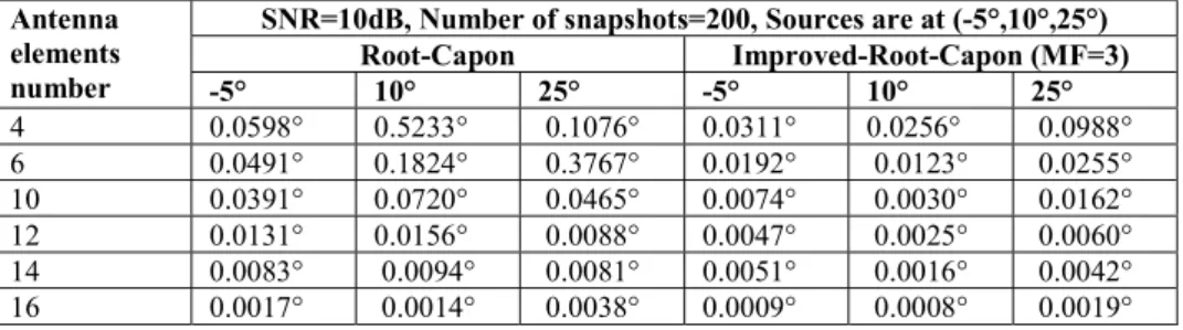
TABLE III.PERFORMANCE OF THE ROOTING METHODS FOR VARYING NUMBER OF ARRAY ELEMENTS.
Antenna elements number
SNR=10dB, Number of snapshots=200, Sources are at (-5°,10°,25°) Root-Capon Improved-Root-Capon (MF=3)
-5° 10° 25° -5° 10° 25°
4 0.0598° 0.5233° 0.1076° 0.0311° 0.0256° 0.0988° 6 0.0491° 0.1824° 0.3767° 0.0192° 0.0123° 0.0255° 10 0.0391° 0.0720° 0.0465° 0.0074° 0.0030° 0.0162° 12 0.0131° 0.0156° 0.0088° 0.0047° 0.0025° 0.0060° 14 0.0083° 0.0094° 0.0081° 0.0051° 0.0016° 0.0042° 16 0.0017° 0.0014° 0.0038° 0.0009° 0.0008° 0.0019°
While the multiplicative factor is an important term in the modification related to the method proposed in this work, and because the improved-root-Capon algorithm is chosen to be considered the best among the techniques studied here, it was worth following the influence of the variation of estimation error versus multiplicative factor value in case of a single source. The simulation results are displayed in Fig. 5. It can say, in brief, that the increase of the multiplicative factor value decreases considerably the error between theoretical and estimated angle values.
Fig. 5. Variation of estimation error versus multiplicative factor (MF) of the improved-root-Capon method.
By using a modified number of elements, the size of the antenna array remains the same, but the antenna processing stage, based on an arrival direction estimation algorithm, considers that the size of the antenna array is greater than the actual one. In other words, the advantage of the proposed algorithm is, on one hand, to increase virtually the number of antenna elements in order to achieve a significant improvement in terms of the algorithmic estimation resolution, and on another hand, to keep the same real number of the elements practically used in order to avoid other problems such as congestion or cost in the antenna system design that must meet compromises in terms of performance and implementation complexity.
1 1.5 2 2.5 3 3.5 4 4.5 5
0 0.5 1 1.5 2 2.5 3 3.5 4
4.5 Variation of estimation error versus multiplicative factor
Multiplicative Factor
E
st
im
at
io
n
Er
ro
r(
%
Brazilian Microwave and Optoelectronics Society-SBMO received 2 June 2018; for review 21 June 2018; accepted 31 Oct 2018 Brazilian Society of Electromagnetism-SBMag © 2018 SBMO/SBMag ISSN 2179-1074
V. CONCLUSION
The proposed variant of Capon can give more estimation accuracy than the conventional Capon method. This last which is a spectral-based method involves plotting the pseudo-spectrum against the angles and searching for the peaks, while root-Capon involves finding the roots of a polynomial which are numerical values.
The choice of the multiplicative factor value should be reasonable and suitable because, a high number of array elements can give, on one hand, true good resolution for Capon algorithm and reduced estimation error for root-Capon. However, on the other hand, this can lead to increase the processing time.
In concluding, we think it is safer say that our modified-algorithm, has clear performance improvements to offer as compared, in this work, to the other studied methods. In fact, we proposed the improved root-Capon as one of performing algorithms to reduce potentially the complexity of the standard Capon algorithm, increase its performance and its capability of resolution.
APPENDIX. PROOF OF IMPROVED CAPON AND IMPROVED ROOTING OF CAPON ALGORITHMS
For these two algorithms, we basically use the new array elements number 𝑁′ which is derived from the modification mentioned in the subsection C of this paper.
The new [𝑁′ × 1] complex envelope representation of the received signals can be expressed as:
𝒙′(𝑘) = 𝑨′(𝜃). 𝒔(𝑘) + 𝒗′(𝑘), 𝑘 = 1, ⋯ , 𝐾
(A1) Where 𝑨′(𝜃) is the [𝑁 × 𝐾] steering matrix, 𝒗′(𝑘) is the [𝑁′ × 1] vector of the noise, and 𝐾
denotes the number of snapshots.
The estimated covariance matrix 𝑹′ for the new vector 𝒙′(𝑘) and the 𝐾 snapshots number can be written as:
𝑹′ =𝐾1 𝒙′(𝑘)𝒙′ (𝑘)
(A2) Now, with the substitution of the new estimated covariance matrix 𝑹′ and the new steering matrix
𝑨′(𝜃), we can easily obtain the following improved-Capon spectrum formula:
𝑃 (𝜃) = 1
𝒂′(𝜃) 𝑹 𝒂′(𝜃)
Brazilian Microwave and Optoelectronics Society-SBMO received 2 June 2018; for review 21 June 2018; accepted 31 Oct 2018 Brazilian Society of Electromagnetism-SBMag © 2018 SBMO/SBMag ISSN 2179-1074
For the improved polynomial rooting of Capon the calculation of roots also depends on the new values of 𝑹′ and 𝑨′(𝜃).
Quite simply, we firstly extract from equation (A3) the following polynomial rooting formula:
𝐷(𝜃) = 𝒂′(𝜃) 𝑹 𝒂′(𝜃)
(A4) Then, we follow exactly the same steps employed for the mathematical development of the root-Capon method as enounced through the subsection B of the present research, to exploit a new technique for AOA estimation.
Finally, the estimation of the AOAs can be deducted from an equation of this from:
𝜽 = −𝑠𝑖𝑛 2𝜋𝑑 . 𝑎𝑟𝑔 (𝒛 )𝜆
(A5) Where 𝒛 are the 𝑖 closest roots to the unit circle.
REFERENCES
[1] L.C. Godara, “Application of antenna arrays to mobile communications. II. Beam-forming and direction-of-arrival considerations,” Proc. IEEE, vol.85, no.8, pp. 1195–1245, 1997.
[2] A. B. Constantine, I. I. Panayiotis, Introduction to Smart Antennas. Morgan & Claypool Publishers’ series, 2007. [3] B. G. Frank, Smart antennas with MATLAB. Second edition, Mc Graw-Hill education, 2015.
[4] M. S. Bartlett, “Periodogram analysis and Continuous spectra,” Biometrika, vol. 37, no.1-2, pp.1-16, 1950.
[5] J. Capon, “High-resolution frequency wave number spectrum analysis,” Proc. IEEE, vol. 57, no.8, pp.1408-1418, 1969. [6] J. P. Burg, “The relationship between maximum entropy spectra and maximum likelihood spectra,” Geophysics, vol.
37, no.2, pp. 375-376, 1972.
[7] O. R. Schmit, “Multiple emitter location and signal parameters estimation,” IEEE Trans. Antennas Propag., vol. 34, no. 3, pp. 276-280, 1986.
[8] R. Roy, K. Kailath, “Esprit-Estimation of signal parameter via rotational invariance techniques,” IEEE Trans. Acoust., Speech, Signal Processing, vol. 37, no. 7, pp. 984-995, 1989.
[9] V. Krishnaveni, T. Kesavamurthy, B. Aparna, “Beamforming for Direction-of-Arrival (DOA) Estimation-A Survey,”
International Journal of Computer Applications, vol. 61, no. 11, pp. 4-11, 2013.
[10]H. Van trees, Optimum Array Processing. Part IV of Detection, Estimation and Modulation Theory. Wiley, New York, 2002.
[11]T. L. Zhang, Y. Liu, G. S. Liao, “Algorithm on high resolution DOA estimation without sources number,” Journal of Electronics & Information Technology, vol. 30, no. 2, pp. 375-378, 2008.
[12]C. Liu, et al., “Modified Capon Beamformer for High-Resolution Direction-of-Arrival Estimation,” International Symposium on Nonlinear Theory and its Applications, NOLTA, September 14-18, Switzerland, pp. 116-119, 2014. [13]G. O. Glentis, “A Fast Algorithm for APES and Capon Spectral Estimation,” IEEE Transactions on Signal Processing,
vol. 56, no. 9, pp. 4207-4220, 2008.
[14]O. K. Abdulrahman et al., Modifying MVDR Beamformer for Reducing Direction-of-Arrival Estimation Mismatch,”
Arabian Journal for Science and Engineering, vol. 41, no. 9, pp. 3321–3334, 2016.
[15]S. W. Cho, J. H Lee, “Efficient Implementation of the Capon Beam-Forming Using the Levenberg-Marquardt Scheme for Two Dimensional AOA Estimation,” Progress in Electromagnetics Research, vol. 137, pp. 19-34, 2013.
[16]J. Selva, “An efficient Newton-type method for the computation of ML estimators in a uniform linear array,” IEEE Trans. Signal Processing, vol. 53, no. 6, pp. 2036-2045, 2005.
[17]T. S. Dhope, D. Simunic, R. Zentner, “Comparison of DoA Estimation Algorithms in SDMA System,” Automatika, vol. 54, no. 2, pp. 199-209, 2013.
[18]S. N. Shahi, M. Emadi, K. Sadeghi, “High resolution DOA estimation in fully coherent environments,” Progress in Electromagnetics researchC, vol. 5, pp. 135-148, 2008.
[19]J.C. Liberti, T. S. Rappaport, Smart Antennas for Wireless Communications: IS-95 and Third Generation CDMA Applications. Upper Saddle River, NJ: Prentice Hall PTR, 1999.
Brazilian Microwave and Optoelectronics Society-SBMO received 2 June 2018; for review 21 June 2018; accepted 31 Oct 2018 Brazilian Society of Electromagnetism-SBMag © 2018 SBMO/SBMag ISSN 2179-1074
[21]B. D. Rao, K. V. S. Hari, “Performance analysis of Root-MUSIC,” IEEE Transactions on Acoustics, Speech and Signal Processing, vol. 37, no. 12, pp. 1939-1949, 1989.
[22]Y. P Liao, A. Abouzaid, “Resolution Improvement for MUSIC and ROOT MUSIC Algorithms,” Journal of Information Hiding and Multimedia Signal Processing, vol. 6, no. 2, pp.189-197, 2015.