Universidade do Minho
Escola de Engenharia
Novembro de 2012Nuno Miguel Eira de Sousa
WildAniMAL
Novembro de 2012
Universidade do Minho
Escola de Engenharia
Departamento de Informática
Nuno Miguel Eira de Sousa
WildAniMAL
MAL Interactors Model Animator
Dissertação de Mestrado
Mestrado em Engenharia Informática
Trabalho realizado sob orientação de
i
Acknowledgements
I want to thank my thesis advisor José Creissac Campos for continuously helping me while doing this work, by making many corrections and valuable suggestions for the implementation of the WildAniMAL and for pointing errors and problems during the design and implementation of the tool.
I also want to thank Manuel Sousa for providing me with a practical example of an Ipod device model, that enabled me to show how the WildAniMAL plugin can be used. Additionally I thank him for testing the WildAniMAL plugin, with interactor models that he developed in his own work.
Finally, I want to thank my employer - Computer Graphics Center – for giving me a day a week for education, during the last three years, thus enabling me to conclude this master’s course with the current work.
ii
Abstract
The IVY Workbench is a tool for modeling and analysis of interactive systems which has been developed at the Department of Informatics of the University of Minho (http://ivy.di.uminho.pt). It's a platform developed in Java, using a plugins mechanism. The available plugins include a set of editors (textual and graphical) and tools to analyse the behaviour of the models. The experience on using the tool has demonstrated the need for a model animator which could enable a first interactive evaluation of the models. Therefore this dissertation describes the design and implementation of WildAniMAL - a MAL (Modal Action Logic) interactors models animator – as a plugin for the IVY Workbench. The plugin uses the NuSMV model checker simulations capabilities, and enables users to explore the formal models interactively.
iii
Resumo
A IVY Workbench é uma ferramenta de modelação e análise de sistemas interativos que tem vindo a ser desenvolvida no Departamento de Informática da Universidade do Minho (http://ivy.di.uminho.pt). Trata-se de uma plataforma desenvolvida maioritariamente em Java, utilizando um mecanismo de plugins. Os plugins existentes incluem um conjunto de editores (em modo texto e gráfico), e de ferramentas de análise do comportamento dos modelos. A experiência de utilização da ferramenta tem, no entanto, demonstrado a necessidade de um animador de modelos que permita efetuar uma primeira validação interativa dos mesmos. Sendo assim, esta dissertação descreve o desenho e implementação do WildAniMAL – um animador de modelos de MAL (Modal Action-Logic) Interactors – como plugin para a IVY Workbench. O plugin usa as capacidades de simulação do model checker NuSMV, e permite aos utilizadores explorar os modelos formais de forma interativa.
iv
Index
Acknowledgements _____________________________________________________ i Abstract _____________________________________________________________ ii Resumo ______________________________________________________________ iii Index ________________________________________________________________ iv Figures ______________________________________________________________ vii Acronyms ____________________________________________________________ ix Chapter 1 – Introduction ________________________________________________ 1 1.1. Goal __________________________________________________________________ 2 1.2. Structure Of The Document _______________________________________________ 2 Chapter 2 – Theoretical Background _______________________________________ 3 2.1. Model Checking _________________________________________________________ 3 2.2. NUSMV _______________________________________________________________ 5 2.3. Finite State Machine _____________________________________________________ 7 2.4. Binary Decision Diagrams _________________________________________________ 9 2.5. MAL Interactors ________________________________________________________ 11 2.6. SMV Language _________________________________________________________ 12 2.7. CTL __________________________________________________________________ 13 2.8. Conclusion ____________________________________________________________ 14 Chapter 3 – IVY Workbench _____________________________________________ 16 3.1. The IVY Workbench Approach ____________________________________________ 16 3.1.1 Creating Models ____________________________________________________________ 17v 3.1.2 Expressing Properties ________________________________________________________ 19 3.1.3 Verification ________________________________________________________________ 20 3.1.4 Trace Analysis ______________________________________________________________ 21 3.2. How To Create An IVY Workbench Plugin ___________________________________ 25 3.3. Conclusion ____________________________________________________________ 28 Chapter 4 – Related Work ______________________________________________ 29 4.1. CTTE _________________________________________________________________ 29 4.2. AniMAL _______________________________________________________________ 32 4.3. Conclusion ____________________________________________________________ 34 Chapter 5 – WildAniMAL Implementation Approaches _______________________ 35 5.1. Implementation Approaches _____________________________________________ 35 5.1.1 Generating a Finite State Machine _____________________________________________ 36 5.1.2 NuSMV Binary Decision Diagrams ______________________________________________ 37 5.1.3 NuSMV Simulation Capabilities ________________________________________________ 37 5.2. NuSMV Interactive Shell _________________________________________________ 39 5.2.1 Model Reading And Building __________________________________________________ 39 5.2.2 Simulation Commands _______________________________________________________ 40 5.2.3 Simulation Example _________________________________________________________ 41 5.3. Conclusion ____________________________________________________________ 46 Chapter 6 – WildAniMAL Implementation _________________________________ 47 6.1. WildAniMAL’s Architecture ______________________________________________ 47 6.2. WildAniMAL’s Source Code Description ____________________________________ 53 6.2.1 Animator Package __________________________________________________________ 53 6.2.2 Constraints Package _________________________________________________________ 62 6.2.3 NuSMV Package ____________________________________________________________ 64 6.3. Conclusion ____________________________________________________________ 68 Chapter 7 – Using WildAniMAL __________________________________________ 70 7.1. WildAniMAL’s Usage Example __________________________________________________ 70 7.2. Conclusion _________________________________________________________________ 80 Chapter 8 – Conclusions and Future Work _________________________________ 81
vi 8.1. Goal _________________________________________________________________ 81 8.2. Results _______________________________________________________________ 81 8.3. Future Work ___________________________________________________________ 83 References __________________________________________________________ 84 Appendix I – Build.xml _________________________________________________ 87 Appendix II – Ipod interactors model _____________________________________ 93
Fig
FIGURE FIGURE FIGURE FIGURE FIGURE FIGURE FIGURE FIGURE FIGURE FIGURE FIGURE FIGURE FIGURE FIGURE FIGURE FIGURE FIGURE FIGURE FIGURE FIGURE FIGURE FIGURE FIGURE FIGURE FIGURE FIGURE FIGURE FIGURE FIGUREgures
E 1 MODEL CHEC E 2 A GRAPH OF E 3 FSM EXAMP E 4 DIAGRAM FO E 5 ROBDD FOR E 6 IVY WORKB E 7 MODEL EDIT E 8 MODEL EDIT E 9 PROPERTIES E 10 BEHAVIOUR E 11 TRACE ANA E 12 TREE VISUA E 13 STATE BASE E 14 LOGICAL ST E 15 TABULAR V E 16 ACTIVITY D E 17 IVY WORK E 18 CTTE TOOL E 19 AN EXAMPL E 20 OVERVIEW E 21 A SIMPLE C E 22 THERMOM E 23 PROTOTYPE E 24 NUSMV SI E 25 INTERACTO E 26 STATE DIAG E 27 NUSMV SP E 28 THE RESULT E 29 THE RESULT CKING SYSTEM, A AN EXTREMELY B PLE OF A PARSER OR , R (X1⇔Y1)^(X2 ENCH ARCHITECT TOR PLUGIN (GRA TOR PLUGIN (TEX EDITOR. ... R TRACE. ... ALYSIS MECHANIS AL REPRESENTATI ED VISUAL REPRE TATES VISUAL RE VISUAL REPRESEN DIAGRAM VISUAL BENCH PLUGINS L, TAKEN FROM [ LE OF A TASK MO OF THE CTT NO CONCURTASKTRE ETER, TAKEN FRO E OF AN AIR CON MULATION EXAM ORS MODEL OF A GRAM OF GATE M PECIFICATION OF T OF PICK_STATE T OF SIMULATE – ADAPTED FROM [ BASIC PROCESS IN RECOGNIZING T TAKEN FROM [1 2⇔Y2) WITH VA TURE. ... APHICAL). ... XT). ... ... ... SMS (MARKERS). ON. ... ESENTATION. ... PRESENTATION. . TATION. ... REPRESENTATIO FRAMEWORK. . [25]. ... ODEL, TAKEN FRO TATION, TAKEN F EE TASK MODEL S OM [29]. ... DITION CONTRO MPLE. ... GARAGE GATE. .. MODEL. ... F THE GATE MODE –I –A COMMAN –I –A –K 1 COMM
vii [9], WITH THE IV N A FINITE STATE THE WORLD "NIC 16]. ... ARIABLE ORDERIN ... ... ... ... ... . ... ... ... ... ... ON. ... ... ... OM [25]. ... FROM [28]. ... SIMULATOR, TAK ... L PANEL, TAKEN ... ... ... EL. ... ND. ... MAND. ... VY WORKBENCH E MACHINE. ... E". ... ... NG X1<X2<Y1<Y ... ... ... ... ... ... ... ... ... ... ... ... ... ... ... KEN FROM [28]. ... FROM [29]. .... ... ... ... ... ... ... APPROACH. ... ... ... ... Y2, TAKEN FROM ... ... ... ... ... ... ... ... ... ... ... ... ... ... ... ... ... ... ... ... ... ... ... ... ... ... ... ... M [17]. ... ... ... ... ... ... ... ... ... ... ... ... ... ... ... ... ... ... ... ... ... ... ... ... ... ... 4 ... 8 ... 9 ... 9 ... 10 ... 17 ... 18 ... 18 ... 19 ... 21 ... 21 ... 22 ... 23 ... 23 ... 24 ... 24 ... 25 ... 30 ... 30 ... 31 ... 32 ... 33 ... 34 ... 38 ... 42 ... 42 ... 43 ... 44 ... 44
viii
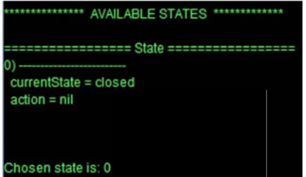
FIGURE 30 THE RESULT OF CHOOSING STATE 0. ... 45
FIGURE 31 STATE BASED DIAGRAM SHOWING THE SIMULATION PATH. ... 45
FIGURE 32 WILDANIMAL PLUGIN ARCHITECTURE AS A PACKAGE DIAGRAM. ... 48
FIGURE 33 MAIN PACKAGE CLASS DIAGRAM. ... 49
FIGURE 34 NUSMV PACKAGE CLASS DIAGRAM. ... 50
FIGURE 35 CONSTRAINTS PACKAGE CLASS DIAGRAM. ... 51
FIGURE 36 TRACES PACKAGE CLASS DIAGRAM. ... 52
FIGURE 37 GRAPHICAL USER INTERFACE IMPLEMENTED BY GUI CLASS. ... 55
FIGURE 38 IPOD MODEL CREATION WITH MODEL EDITOR PLUGIN. ... 71
FIGURE 39 IPOD INTERACTOR MODEL COMPILATION WITH PROPERTIES EDITOR PLUGIN. ... 72
FIGURE 40 RESULT OF PRESSING “GET INITIAL STATE” IN WILDANIMAL. ... 73
FIGURE 41 SIMULATION REACHED A “TOO MANY STATES” SITUATION. ... 74
FIGURE 42 STATE BASED REPRESENTATION OF THE TRACE CREATED IN THE SIMULATION. ... 75
FIGURE 43 TABULAR REPRESENTATION OF THE TRACE CREATED IN THE SIMULATION. ... 75
FIGURE 44 LOG REPRESENTATION OF THE SIMULATION. ... 76
FIGURE 45 CONSTRAINTS INSERTION. ... 77
FIGURE 46 RESULT OF APPLICATION OF THE CONSTRAINTS SENT. ... 77
FIGURE 47 STATE BASED REPRESENTATION OF A TRACE ORIGINATED IN A SIMULATION. ... 79
ix
Acronyms
BDD Binary Decision Diagrams CMU Carnegie Mellon University CTEE ConcurTaskTrees Environment CTL Computacional Tree Logic CTT ConcurTaskTrees
CUDD CU Decision Diagram Package ETC Enabled Task Collection FSM Finite State Machine
IRST Istituto per la Ricerca Scientica e Tecnologica IVY Interactors VerifYier
LTL Linear Temporal Logic MAL Modal-Action Logic RBC Reduced Boolean Circuit SAT Satisfiability Problem SMV Symbolic Model Verifier UI User Interface
1
Chapter 1 – Introduction
Developing complex systems will always be a complex endeavour. When developing interactive devices, we are faced with the challenge of understanding not only how the device must be built, but also how it will interact with its users, and how both device and users (the interactive system) will influence each other.
Formal (mathematically rigorous) methods have long been proposed as a means of dealing with complexity. When considering the behaviour of systems, model checking [1] has gained particular popularity. Several approaches to the application of model checking to reason about interactive systems (or interactive devices) have been put forward over the last seventeen years. See, for example, the work in [2], [3], or [4]. However, applying model checking is in itself a complex task. Both systems and Properties to be verified must be expressed in appropriate logics. In order to make model checking of interactive systems feasible, we must provide tools that help in the modelling and analysis process.
The IVY Workbench tool supports the modelling and verification approach put forward in [3]. The main goal of the tool is the detection of potential usability problems early in development of any interactive system. For that, the tool enables the automated inspection of interactive systems models. The tool supports a modelling and analysis cycle where the models are obtained by a modelling process based on an editor, the properties are expressed using a dedicated properties editor, the analysis is performed using the SMV model checker [5] (more specifically NuSMV [6], a reimplementation of that tool, that is available at http://nusmv.fbk.eu), and the counter-examples visualized using a dedicated traces visualiser. The tool has been applied to the analysis of different devices, from control panels in the automotive industry [7], to medical devices such as infusion pumps [8]. While model checking through NuSMV, enables a thorough analysis of all possible behaviours of a model, the continuous use of the tool has highlighted the need for a
2
lighter weight approach to the initial validation of the models. In fact, experience has shown that before the analysis of a given design begins, there usually happens a first phase of model validation, where the interest is in establishing that the model behaves as expected. Experience also shows that doing this through model checking becomes cumbersome. What is needed is the possibility of interactively explore the behaviour of the models: manually trigger events and observe how the system evolves. Hence the need was identified of developing a component aiming at assisting the modelling and analysis process, by providing functionalities to simulate and validate the model being created: WildAniMAL (Watch It vaLiDation Animator for MAL).
1.1. Goal
The goal of this work is to develop a new plugin – WildAniMAL – for the IVY Workbench tool, supporting the animation of MAL interactor models. In order to implement it, three possibilities will be studied:
a) representing a MAL interactors model as a Finite State Machine (FSM) and use that to drive the animation;
b) use the BDD (Binary Decision Diagrams) representation of the MAL interactors model, created by the NuSMV model checker to perform the animation;
c) use the NuSMV model checker simulations commands, available on its interactive mode, to perform the animation.
1.2. Structure Of The Document
This first chapter has presented the motivation and goals of the work. The remaining of the dissertation is structured as follows. Chapter 2 introduces the main concepts needed to understand the work. Chapter 3 introduces the IVY workbench tool. Chapter 4 describes some related tools. Chapter 5 discusses alternatives to implementing the WildAniMAL plugin, and chapter 6 the implementation produced. Chapter 7 describes an usage example. The dissertation ends, in Chapter 8, with a discussion of results and ideas for further work.
3
Chapter 2 – Theoretical
Background
This chapter presents the theoretical background needed to explain the WildAniMAL implementation and all the concepts related to its use, and the use of the IVY Workbench, in which it will be integrated.
Section 2.1 presents Model Checking the technology used by the IVY Workbench to perform verification. Section 2.2 presents NuSMV that is the model checker used in IVY Workbench, and therefore also used to implement WildAniMAL’s functionalities. Section 2.3 presents Finite State Machines, a mathematical model of computation, and also a state’s representation, widely used to describe computer programs. Section 2.4 presents Binary Decision Diagrams, the data structure used to represent a Boolean function. Two representations used in NuSMV as internal representations. Section 2.5 presents the MAL interactors language used to create models that will be simulate in the WildAniMAL plugin, and Section 2.6 presents the SMV language, the language into which MAL interactors models are compiled for verification and (now) animation.
Finally, CTL is presented, that is a temporal logic that is used to express properties over the interactors model. These properties can be verified using NuSMV model checker.
2.1. Model Checking
Clarke [9] formally describes the Model Checking problem as:
Let M be a Kripke structure (i.e., state-transition graph). Let f be a formula of temporal logic (i.e., the specification). Find all states s of M such that M; s |= f.
T satisf T Figure F mode Sectio
That is, given fy the specific The structure e 1. There th A pre A mo temp the IV Figure 1 Mo Figure 1 inclu el checking on 3.1. n a state-tran cation. e of a typica he two mains eprocessor odel check poral formula VY Workbenc odel checking udes IVY Wo process. Th sition graph l Model Che s components r that extracts ker, that is,
a and determ ch this is NuS g system, ada rkbench’s pl he IVY Work 4 and a specif ecking system s of a model s a state tran an engine th mines whethe SMV). apted from [9 ugins and se bench appro fication, we w m, as Clarke checking sy nsition graph hat takes the er the formul 9], with the I ervices that h oach to Mod want to find a defined it [9 stem are pre from a prog e state trans a is true or n VY Workbenc help in the se del Checking all states in M 9], is describ esented: gram or circu sition graph not (in the c
ch approach everal steps g is present M that bed in it; and a ase of . of the ted in
5
There are other verification techniques other than Model Checking, such as Automated Theorem proving or Proof Checking. Therefore is useful to present the advantages that Model Checking has when compared to them. Some of these advantages are:
It provides counterexamples. In a model checker, a counterexample (an execution trace) is produced to show why a specification does not hold. This is a great advantage because counterexamples are great to debug complex systems. Some people use Model Checking just for this feature;
It uses Temporal Logics that can easily express properties for proving over the behaviour of modelled systems. One example of these Temporal Logics is CTL, which is described in Section 2.7. CTL is used in the IVY Workbench tool.
In the opposite side there are also some disadvantages and one of the major ones is State
Explosion. In [3] the authors describe this problem as related to the size of the finite state
machine (this concept will be described in Section 2.3) needed to specify a given system. A specification can generate state spaces so immense that it becomes impossible to analyse the entire state space. To attenuate this problem, Symbolic Model Checking was developed. When the traversal of the state space is done considering large sets of states at a time, and is based on representations of states sets and transition relations as formulas, binary decision diagrams or other related data structures, the model-checking method is considered Symbolic. With that technique state spaces as large as 1020 may be analysed [10]. NuSMV is a model checker that
uses that method and will be described in the following Section.
2.2. N
USMV
NUSMV is a symbolic model checker that was first presented in [6] and [11]. It is the result of a joint project between Carnegie Mellon University (CMU) and Istituto per la Ricerca Scientica e Tecnologica (IRST) and is the final product of an effort of reengineering, reimplementation and extension of CMU SMV, the original BDD-based model checker developed at CMU [5].
Over the years NuSMV had several contributions that improved it with more functionality, as can be seen in its official site1. Now it combines a BDD-based model checking component that
6
exploits the CUDD2 library developed by Fabio Somenzi at Colorado University, and a SAT-based
model checking component that includes an RBC-based Bounded Model Checker, which can be connected to the Minisat SAT Solver3 and/or to the ZChaff SAT Solver4. The University of Genova
has contributed SIM, a state-of-the-art SAT solver used until version 2.5.0, and the RBC package used in the Bounded Model Checking algorithms.
In [12] we can see the current main functionalities that it provides:
allows for the representation of synchronous and asynchronous finite state systems; allows for the analysis of specifications expressed in Computational Tree Logic (CTL)
and Linear Temporal Logic (LTL), using BDD-based and SAT-based model checking techniques.
provides Heuristics for achieving efficiency and partially controlling the state explosion;
provides a textual (interactive mode) and a batch mode interface to interact with its users.
NuSMV, as a model checker, can verify properties of a finite system and for that to be possible a model of the system (in fact, in terms of model checking, a specification of the system) has to be created. NuSMV uses the SMV Language (see Section 2.7) to define the specifications used as input. In [13] it is described how this language can be used to allow for the description of Finite State Machines (FSM) which can be completely synchronous or completely asynchronous. More specifically the SMV Language is used to describe the transition relation of the FSM that describes the valid evolutions of the state of the FSM.
In the IVY Workbench, that model is created in the MAL Interactors language (see Section 2.5), that is easier to learn and can be compiled (using the IVY Workbench i2smv service) into a SMV specification. After having a SMV specification, NuSMV can verify that a model satisfies a set of desired properties specified by the user. For that, it uses two Temporal Logics: CTL or LTL.
One useful feature that NuSMV has is that it provides the user with the possibility of simulating a NuSMV specification. As stated in [13], this way the user can explore the possible
2 http://vlsi.colorado.edu/~fabio/CUDD/ Last visited in 10-28-2012. 3 http://minisat.se/ Last visited in 10-28-2012.
7
executions (traces) of the NUSMV specification. In this way, the user can check the specification correctness, before actually engaging in the verification of properties. An example of the use of this feature can be seen in Section 5.2.3.
2.3. Finite State Machine
When modelling the behaviour of systems, State Machines are one of the oldest and best ways known. They define the state of a system at a particular point in time and characterize its behaviour based on that state.
If we want to model and design software systems we can apply the State Machines method by identifying the states the system can be in, which inputs or events trigger state transitions, and what system behaviour is expected in each state. The execution of the software can be seen as a sequence of transitions that move the system through its various states.
The characteristics of a system that enable it to be modelled as a Finite State Machine (FSM) are [14]:
The system must be specifiable as a finite set of states;
The system must have a finite set of inputs and/or events that can trigger transitions between states;
The behaviour of the system at a given point in time depends upon the current state and the input or event that occur at that time only;
For each state the system may be in, behaviour is defined for each possible input or event;
The system has a particular initial state.
T math A Figur The concept ematically) [ is is is is autom is An example o re 2 A graph tual definitio 15] as a quin
the input alp a finite, non-s an initial non-sta the state-tra maton it beco s the set of fi of the graphic of an extrem on of the F ntuple phabet (a fini -empty set of ate, an eleme nsition funct omes nal states, a cal represent 8 mely basic pro
SM can be ite, non-empt f states. ent of . tion: (possibly em tation of a FS ocess in a fin expressed , where: ty set of sym , i.e., mpty) subset SM is presen
nite state mac more forma bols). (for a nond returns a of . ted in Figure chine. ally (in this
deterministic set of states e 3. case c finite s).
2.4
B repre repre A acycl F4. Binary
Binary Decis esent a Boole esentation of Andersen [17 ic graph with one a se two varia Figure 3 FSMy Decisio
ion Diagram ean function sets or relati 7] provides h: or two termi et of variable functions lo able node. Figure M example ofon Diagr
s (BDD) [16 (see Figure ons. a formal def nal nodes of e nodes u of ow(u) and e 4 Diagram 9 f a parser recrams
6] can be de 4 for an ex finition of a f out-degree z out-degree high(u). A for cognizing the efined as a xample). We BDD. He de zero labeledtwo. The two variable va
, taken from
e world "nice
data structu can also say efines it as 0 or 1, and o outgoing e ar(u) is asso m [16]. ". re that is us y it a compr a rooted, di
edges are giv ociated with sed to ressed rected ven by each
W define linear A Fig When mentio es a BDD as r order x1 < x An (O)BDD i (uniq and and (non low(u gure 5 ROBD oning BDDs Ordered (OB x2 < … < xn. is Reduced ( queness) no high-success var(u) = var( n-redundant t u) ≠ high(u). DD for (x1⇔y1 it is import BDD) if on al R(O)BDD) ( two distinct sor, i.e., (v); low(u) = l tests) no vari 1)^(x2⇔y2) w 10 tant to ment ll paths throu (see Figure 5 nodes u and low(v); high(u iable node u with variable tion if they a ugh the grap 5) if d v have the u) = high(v) i has identica ordering x1< are ordered h the variabl same variab mplies u = v al low- and h <x2<y1<y2, ta or not. And les respect a ble name an v; high-successo aken from [1 dersen given d low- or, i.e. 17].
11
In most cases, when BDDs are referred to, it is implied that we are referring to Reduced Ordered Binary Decision Diagrams.
Bryant [18] studied the BDD potential for being used to create efficient algorithms. He introduced a fixed variable ordering (for canonical representation) and shared sub-graphs (for compression). After that he extended the sharing concept to several BDDs, i.e. one sub-graph by several BDDs and, doing that, he defined the data structure Shared Reduced Ordered Binary Decision Diagram. That new structure is normally what people have in mind when mentioning BDDs.
The NuSMV model checker uses BDDs, because they are very efficient and can be used to create efficient algorithms, as shown in [18]. The efficiency of algorithms is important in the area of Model Checking, and because of that the use of BDDs by NuSMV was an obvious choice.
2.5. MAL Interactors
MAL interactors follow from the notion of interactor put forward in [19]: an object with the capability of rendering part of its state to some presentation medium. A MAL interactor is defined by:
a set of typed attributes that define the interactor's state; a set of actions that define operations on the set of attributes;
a set of axioms written in MAL [20] that define the semantics of the actions in terms of their effect on interactor's state.
The mapping of the interactor's state to the presentation medium is accomplished by decorating the attributes with modality annotations. MAL axioms define how the interactor's state changes in response to actions being executed on the interactor. In [3] the axioms are defined in five types. In the syntax of each type, the notation prop(expr1,..,exprn) is usedto denote a formula
on expressions expr1 to exprn using propositional operators only. Also, the names a1 to an denote interactor attributes and ac denotes an action. The five types are:
Invariants – these are formulae that do not involve any kind of action or (reference) event (i.e. simple propositional formulae). They must hold for all states of the interactor;
12
Initialisation axioms – these are formulae that involve the reference event ([]). They define the initial state of the interactor;
o Syntax: [] prop(a1,..,an).
Modal axioms – these are formulae involving the modal operator. They define the effect of actions in the state of the interactor;
o Syntax: prop([ac] a1,..,[ac]ag, ah,..,an).
Permission axioms – these are deontic formulae involving the use of per. They define specific conditions for actions to be permitted to happen;
o Syntax: per(ac) → prop(a1,..,an)
Obligation axioms – these are deontic formulae involving the use of obl. They define the conditions under which actions become obligatory.
o Syntax: prop(a1,..,an) → obl(ac)
2.6. SMV Language
The SMV language will be used as an intermediate representation of the MAL interactors model. Therefore an explanation of the main aspects of the SMV language is needed. The following description of the language is adapted from [3] and [12].
An SMV specification is defined as a collection of modules. Each module defines a Finite State Machine (FSM) and consists of a number of state variables, input variables and frozen variables, a set of rules that define how the module makes a transition from one state to the next and Fairness conditions that describe constraints on the valid paths of the execution of the FSM.
A state model is defined as an assignment of values to a set of state and frozen variables. State variables can change their values throughout the evolution of the FSM. Frozen variables cannot, as they retain their initial value, and that is what distinguishes the two. Input variables are used to label transitions of the Finite State Machine.
An example of an SMV specification is the following:
MODULE main -- attributes VAR
13
lastDisplay: {MainMenu, Music, Playing, OFF}; playbackState: {playing, paused, stoped}; display: {MainMenu, Music, Playing, OFF}; -- actions
VAR
action: {pause, longPlay, play, nil}; -- axioms
INIT display = OFF
INIT playbackState = stoped INIT lastDisplay = MainMenu INIT currentSong = 0
TRANS next(action)=pause -> playbackState = playing
TRANS next(action)=play -> playbackState = stoped | playbackState = paused
INIT action = nil
To create a SMV specification the following list of declarations is used: VAR allows the declaration of state variables;
IVAR allows the declaration of input variables;
FROZENVAR allows the declaration of frozen variables; INIT allows the definition of the initial states of the model; INVAR allows the specification of invariants over the state.
TRANS allows the definition of the behaviour of the model. In these definitions, the operator next is used to refer to the next state;
FAIRNESS allows the declaration of fairness constraints, that is, conditions that
must hold infinitely often over the execution paths of the model.
2.7. CTL
When reasoning about the behaviour of a system is needed, CTL can be used to express the properties for that purpose. The detailed description of CTL and its formal description are available in [21]. A more compact description of its operators is given here. As other similar languages CTL provides propositional logic connectives but it also allows for operators over the computation paths that can be reached from a state.
14 A - for all paths (universal quantifier over paths); E - for some path (existential quantifier over paths). and over states in a computation state:
G - used to specify that a property holds at all the states in the path (universal quantifier over states in a path);
F - used to specify that a property holds at some state in the path (existential quantifier over states in a path);
X - used to specify that a property holds at the next state in the path;
U - used to specify that a property holds at all states in the path prior to a state where a second property holds.
These operators provide for an expressive language because combining them it is possible to express important concepts such us:
universally: AG(p) - p is universal (for all paths, in all states, p holds);
inevitability: AF(p) - p is inevitable (for all paths, for some state along the path, p holds);
possibility: EF(p) - p is possible (for some path, for some state along that path, p holds).
2.8. Conclusion
This chapter presented all the theoretical background needed to explain the WildAniMAL implementation and the tool in which it is integrated – the IVY Workbench.
Section 2.1 presented Model Checking that is the area in which this work is framed, and Section 2.2 presented NuSMV that is the model checker used widely in IVY Workbench, and which will also be used in the WildAniMAL plugin.
Sections 2.3 and 2.4 presented Finite State Machine and Binary Decision Diagrams, two representations studied as possible approaches for WildAniMAL’s internal data structure. BDD is used also in NuSMV as one of its data structures.
Section 2.5 presented the MAL interactors language used to create interactor models, and Section 2.6 presented the SMV language that will be used as an intermediate representation of the first one, because it is the language NuSMV uses.
15
Finally, CTL was presented. This language is used to express properties over the interactor models, created with the MAL interactors language, and compiled to a NuSMV specification.
16
Chapter 3 – IVY Workbench
This chapter presents the IVY Workbench tool that supports the modelling and analysis of interactive systems. It is a plugins platform (developed in Java) that includes a set of editors and tools to analyse the models’ behaviour.
Section 3.1 presents the IVY Workbench approach, relating to model checking, that consists on creating a MAL model, expressing properties over it, making a verification with the help of the NuSMV model checker and analysing its results.
Section 3.2 describes how to create a new plugin for the IVY Workbench, as this is useful to know how to implement the proposed WildAniMAL plugin.
3.1. The IVY Workbench Approach
In [3] and [4] an approach to the application of model checking to the analysis of interactive systems is put forward. The approach is based in the development of models of the interactive device, and in their verification trough model checking against properties that encode assumptions about the usages of the device.
Figure 6 shows the architecture of the tool, added with the proposed WildAniMAL plugin. As it can be seen, the tool consists on a number of plugins, and uses NuSMV as the verification engine. In this section the different plugins are described (except WildAniMAL, which will be discussed later, see Chapter 7).
3.1.
A MAL mode [22]).1 Creati
A MAL mode model creat es: Graphical and Text (seing Mode
el is construc tion is suppo (see Figure ee Figure 8) t Figure 6 IVYls
cted compos orted by the 7) that uses that provides 17 Y Workbench sing interacto e Model Edit a notation s s code compl architecture ors in a hier tor plugin of similar to UM etion facilitie . rarchical form the tool. Th L class diagr es. m. The proc he plugin ha rams (descri ess of as two bed inFigure 7 Mode Figure 8 Mo 18 el Editor plug odel Editor p gin (Graphica plugin (Text). al).
3.1.
T assum T Work prope descr param the u the to for th.2 Expre
The propertie mptions abou The process bench tool erties typicall ribed in [23] meters. After ser of the too ool has an a e parameterssing Pro
es for verific ut the expect of expressin (see Figure y verified of . Each patte r choosing th ol has only to ssisted mod rs of the patteoperties
cation are w ted behaviou g properties 9). The plu any interactiv rn describes he most suite o define the e, in which t ern. Figure 19 written in CT r of the devic is supported ugin is based ve system. T its intent, p ed pattern fo values of the the user sele9 Properties L [1]. Prope ce. d by the Prop d on sets o The patterns rovides a pra or the propert e parameters ects attribute s Editor. erties are wr perties Edito f patterns th used by the I actical exam ty he or she s of the patte es and action ritten that ex or plugin of th hat capture IVY workbenc ple and has wants to ex ern. For doing
ns from the xpress he IVY usual ch are some press, g that, model
20
3.1.3 Verification
The verification step is performed by the NuSMV model checker. To make the verification possible, MAL interactor models are compiled to the SMV language. A detailed description of the verification approach is out of the scope of this dissertation. For the discussion that follows what is important is that, when a given property is not verified, NuSMV tries to provide a behaviour of the model (a trace) that demonstrates the falseness of the property in question. These traces (see Figure 10 for an extract) consist of a sequence of states of the model that violates the property under scrutiny.
Because of limitations on the SMV input language, when compared to MAL interactors, the compilation step mentioned above introduces a series of auxiliary variables in the model. This means that the trace is not at the same level of abstraction as the interactor model being verified. One aspect were this is particularly evident is the treatment of actions. Because SMV models do not have an explicit notion of action, the compilation process introduces a special attribute - action - used for modelling, in each state, which action has just occurred.
Another aspect that deserves mention is a mismatch in the execution models of both languages. At MAL interactors level, the actions of different interactors can happen in an asynchronous way. Thus, an interactor can execute one action while the others remain inactive. At the SMV level, however, the transitions occur in a synchronous way. This means that when a module performs a transition all modules in the model must also perform a transition. To model asynchronous state transitions, it becomes necessary to introduce a special action nil that at the MAL interactors level (what we will call the logical level from now on) corresponds to nothing happening, while at SMV level (what we will call physical level from now on) represents a state transition (to a state with the same attributes values i.e. to the same logical state). This way, the SMV module corresponding to an interactor can perform a state transition associated to a given action, while the others execute the action associated to nil (that is, maintain the state).
3.1.
T and s as m of the mode appro C depen and c analy and i repre.4 Trace
The traces pr states existing entioned abo e trace's me el. A typical opriate repres Counter-exam nding on the complex. The ysis step, helin discoverin esentations a
Analysis
roduced by t g at the SMV ove). Thus, it eaning can b l example w sentation of t mple traces c e complexity e Traces Vis ping in deter ng possible s nd trace ana Figure Figure he verificatio V code level (s t is necessar be performe would be el the notion of can, howeve of the mod sualizer plugi rmining what solutions to i lysis mechan e 11 Trace A 21 10 Behaviou on process d some of whic ry to revert th d at the lev limination o f action. er, reach sizeel. Hence th in, of the IVY t the problem it. To achiev nisms (marke Analysis mech ur trace. o, as we can ch were intro he compilatio vel of abstrac f attribute a es in the ord heir analysis Y Workbench m is that is b ve these goa
ers) that can
hanisms (ma n expect, men oduced at the on process so ction of the action, repla der of the hu can become h tool, aims being pointed als the plugin be seen in F
rkers).
ntion the var e compilation o that the an original inte acing it by undreds of s e time cons at facilitatin d out by the n resorts to Figure 11. riables n step, nalysis eractor some states, uming ng this trace, visual
T The available Trace - th Tree (see State Bas Logical S trace stat process; Tabular (s Cadence Activity D Activity di visual repres he original tex Figure 12) -sed (see Figu tates (see Fi tes are pre-p see Figure 1 Labs; Diagram (see iagrams (follo sentations ar xtual represe tree represe re 13) - grap igure 14) - r rocessed to 5) - tabular r e Figure 16) owing the no Figure 12 Tr 22 re fully descr entation prod entation of th phical represe representatio eliminate art representatio ) - represen otation of UM
ree visual rep
ibed in [24] uced by SMV e trace state entation of th n similar to tificial states on similar to tation focuse L 2.0 describ presentation.
and are the f V;
es;
he trace state the previous
introduced b the one exis ed on action bed in [22]. . following: es; s one in whic by the comp sting in the S ns that reso ch the pilation SMV of orts to
Figu Figu ure 13 State re 14 Logica 23 Based visua al States visu al representat al representa tion. ation.
F Figure Figure 15 Tab e 16 Activity 24 bular visual r Diagram vis representatio ual represent n. tation.
3.2
T imple simpl pane Figure T. How T
The IVY Work ementing an lification pur so that the u e 17, the Mo The interface publ Exce cycle proc tool.To Creat
kbench is a m interface t poses a plug user can seleodel Editor Figu e methods tha lic void i eption th e of the too essing and a
te An IVY
modular tool that defines gin can also ect between , Properties ure 17 IVY Wo at must be im init(IServer his method in l. It receives also a param 25Y Workbe
based on plu the method be called a all the toolss Editor and orkbench Plu mplemented r coreServ nitializes the s a paramet meter that co
ench Plu
ugins. A plug ds needed tool. Each to loaded into t d Traces An ugins Framew to construct ver, IToolP Tool. This m ter that is th ntains a refeugin
gin is integrat for integratio ool will be pl he framewor nalyzer tools work. a tool are th Properties method is call he server us erence to theted into the t on purposes laced on a t rk. For exam s are represe he following: prop) th led once in t sed to hand e properties o tool by s. For abbed ple, in ented. hrows he life le the of this
26
public void initGUI(JFrame main, JComponent rootContainer) this method is used to initialize the Graphic User Interface for the tool. This method is also called once only in the life cycle of the tool. It receives the main JFrame of the IVY Workbench tool and also receives the container in which the tool graphic component can be added.
public void gainFocus() this method is to be invoked whenever the tool is selected in the main tabbed pane of IVY Workbench tool. With this method we can control what we want to do each time the tool gains control. For example if some global data is changed by others tools then the current tool can also change its state (by changing graphical elements or internal data) to reflect them.
public void loseFocus() this method is used whenever the tool loses the control (is de-selected). With this method we can control what we want to do when the user switches to other tool. For example the current tool can put some data in a global area (common to all tools) so that the other tools can query if some global data is available, and if so reflect some changes on their own states, by changing graphical elements or internal data.
public boolean needsSaving() this method is used to tell if the tool needs to save its data when a project is being saved.
public boolean needsFocus(int event) this method is used to return the status related to focus. It receives a parameter that is the event by which the tool needs focus. The event codes are the following:
o int EVENT_OPEN_PROJECT = 0; o int EVENT_NEW_PROJECT = 1; o int EVENT_SAVE_PROJECT = 2; o int EVENT_CLOSE_PROJECT = 3; o int EVENT_EXIT_PROGRAM = 0.
27
public void newProject(IProjectProperties proj) this method is invoked whenever the main application creates a new project. It receives the project properties (name, project working directory, author, etc.).
public void openProject(IProjectProperties proj, String[] files) this method is invoked whenever the main application opens a project. It receives the project properties and also the paths of the folders belonging to this tool.
public String[] saveProject(IProjectProperties proj) this method is invoked whenever the user wants to save the current project. It will be up to the tool to save its own data files. This method receives the project properties as a parameter and returns the paths of the folders belonging to this tool.
public void closeProject(IProjectProperties proj) this method is invoked whenever the IVY user wants to close the current project. It receives the project properties.
public void exit() this method is invoked whenever the user exits the IVY Workbench.
The configuration file plugin.xml is needed to properly configure the tool. The following text explains how to fill the data fields of this configuration file.
The structure of the XML file is the following:
<?xml version="1.0"?>
<!DOCTYPE plugin PUBLIC "-//JPF//Java Plug-in Manifest 0.4" "http://jpf.sourceforge.net/plugin_0_4.dtd">
<pluginid=’tool name’ version=’tool version’ > <requires>
<importplugin-id="CoreSystem"/> </requires>
28
<runtime>
<libraryid=’tool library name’path=’tool jar filename’type="code"> <doccaption="API documentation">
<doc-refpath="api/index.html" caption="javadoc"/> </doc>
</library>
<librarytype="resources"path="icons/"id="icons"/> </runtime>
<extension plugin-id="CoreSystem"point-id="Tool"id=’tool name’> <parameterid="class"value=’tool java main class name’ /> <parameterid="name"value=’tool name’ />
<parameterid="description"value=’tool description’ /> <parameterid="icon"value=’tool icon filename’ /> </extension>
</plugin>
The values between quotes have to be replaced to fill the configuration file. For example, to make the configuration file of Model Editor tool the values are instantiated in this way:
‘tool name’= “ModelEditor”
’tool version’= “0.0.1”
’tool library name’= “Model Editor”
’tool jar filename’= “ModelEditor.jar”
’tool java main class name’= ”Editor.Editor”
‘tool description’= “Model Editor description”
‘tool icon filename’= “modelEditor.gif”
In the tool’s directory a “build.xml” file is also needed. This file is used to build the tool with the help of the “plugin.xml” configuration file. The build.xml (see Appendix I) is the same for any tool (only the project name can be changed).
3.3. Conclusion
This chapter presented the IVY Workbench tool that supports the modelling and analysis of interactive systems. Section 3.1 presented the model checking based approach supported by the tool. Section 3.2 described how to create a new plugin for that tool.
29
Chapter 4 – Related Work
This chapter describes CTTE (ConcurTaskTrees Environment) a task modeling tool that has animation and simulation strategies that are similar to the ones intended to be used on the proposed MAL models animator plugin. A previous IVY Workbench plugin - aniMAL - that had a similar goal to this work will also be described.
4.1. CTTE
CTTE5 (see Figure 18) is an environment for editing and analysing task models. Its main goal
is to support the design of interactive applications focusing in the humans and their activities. In [25] the concepts behind tasks models are presented. In is an important model because it indicates the logical activities that an application can support. A task is defined as an activity that should be performed by the user to reach a goal in the system. A goal can be a desired modification of state or a query to obtain information on the current state of the system. Figure 19 presents an example of a Tasks model.
CTTE uses ConcurTaskTrees (CTT), introduced by Fabio Paternó in [26] and [27]. CTT is a graphical notation (see Figure 20 for an example) with a set of operators used to describe the relationships between tasks.
Figure 19
Figure 18 CT
9 An example 30 TTE tool, take
e of a task m
en from [25]
model, taken f .
C Conc reach depen The f the s speci C in a perfo CTTE provid urTaskTree h a pre-define nding on wha first step in s same time a fic task mod CTTE’s tasks list. Double-c rmed, the en Figure 20 es a simula involves sim ed goal. In a at tasks have simulating Co nd that is c el is referred s simulator is clicking on a nabled tasks 0 Overview of ation functio ulating, in s ConcurTaskT e been perfor oncurTask-Tr alled an ena to as an ena a basic one a task will si are updated 31 f the CTT not onality that some way, t kTree, tasks a rmed, some rees is to ide abled task s abled task co e (see Figure imulate the accordingly. tation, taken is described he execution are disposed tasks are en entify the task set. The set
ollection (ETC 21). It displa performance from [28]. d in [28]. T n of specific in a hierarch abled and ot ks that are lo of all enable C).
ays the curre e of that task
The simulat tasks in ord hical style. T thers are dis ogically enab ed task sets ently enabled k. When a t tion a der to hat is, abled. bled at for a d tasks task is
C the C simul differe MAL some I action reach tasks
4.2
A Work of the action T of the IMode updat Visua value Figure CTTE is a goo CTTE environ lation capab ences to the models in t ething that do t is expected ns of the MA hable states ( of CTTE.. AniMA
AniMAL, des bench. Its m e interface to n, of a widge The AniMAL e IVY Workb el data is u tes it with m alizer plugin s, representi 21 A simple od case stud ment (see Fi bilities. This proposed W the other), a oes not happ d that the Wi AL interactor (enabled by aAL
scribed in [2 most salient fe o be used du t in order to tool obtains bench. More pdated by t model data, updates it w ing behaviou e ConcurTask y on how a M gure 21) to t concept an WildAniM plug nd also that en in CTTE. ldAniMAL plu s will be rep a interactor a 29], is a pr eature is that uring the anicreate the pr the data tha specifically, two other pl
which consi with fail trac rs of the mod 32 kTree task m MAL models the present w nd the capa gin will be th t we have a ugin will hav presented by action on a s rototype of a t of supportin mation. It al rototype. at it needs to , from the I ugins of the ists of intera ces (sequenc del). odel simulat animator sho work is its co bilities are e supported ttributes in t ve a similar b y similarly to specific state a plugin tha ng the definit lows the ass o perform its Model (inter e IVY Workbe actors, attrib
ces of state
or, taken from ould function oncept of ena described in model (Task the states of behaviour to CTTE tasks, e) will be sim at was deve tion, at runtim ociation, to e function from ractors mode ench. The M utes and ac s, defined b m [28]. n. The releva abled tasks a n [28]. The ks in one cas of the MAL m that of CCTE , and the po milar to the en loped for th me, of a pro each attribut m the CoreS el) data stru ModelEditor ctions. The T by their attri nce of and its main se and model, E. The ossible nabled he IVY totype te and System ucture. plugin Traces butes’
W mode or ma choos have autom T I attrib show T graph these provid propt intera What is intere el it pulls from anual. First sing which g the plugin p matically, the The default c f the mappin ute. For exam w the changes The list of w hic evolution e cases (e.g. de an easier totype with t actors model esting and us m the CoreSy it creates an graphical elem perform that en the interac components’ interactor – r attributes – r actions – ren ng is perform mple, for a t s in the temp Fi widgets in An of the values State or Ac r insight into the different . seful in AniM ystem. It use n interactor ments will re mapping au ctors’ attribut rendering is rendered as rendered usi ndered as bu med manuall emperature perature value gure 22 The niMAL is ext s of the attrib ctivity Diagram o the behavio t widgets us 33 MAL is that it es a mapping tree from th ender each o utomatically.
tes and actio as follows: panel; ng the defau uttons. ly, we can c attribute we e, as modelle rmometer, ta tensible, wh butes, instea ms). Theses our of an in sed for each
can generat g generation he data mod of the interac If we reques ons are rende
lt widget for hoose the w can use a th ed by the att aken from [2 ich makes i ad of the trad widgets are nteractors mo h of the att e a UI protot strategy that el. Then we tors’ attribut st for the ma ered with defa
their type; widget that is hermometer ribute. 9]. t very appea ditional repre e more famil odel. Figure ributes of a
type from the t can be auto e can opt be
tes and actio apping to be fault compon s assigned to (see Figure aling to prov esentations u
iar and pote 23 presents an Air-Condit e data omatic etween ons, or e done ents. o each 22) to vide a sed in entially s a UI tioning
A traces anima
4.3
T previo usefu Figu AniMAL’s an s, That is d ate the intera. Concl
This Chapter ous IVY Work ul insights int ure 23 Protot imation capa ifferent from actors modellusion
r described kbench anim to what the W type of an air abilities, how m what has ls themselves CTTE (Conc mation plugin WildAniMAL p 34 r condition co wever, are lim been defined s. curTaskTrees n - aniMAL – plugin should ontrol panel, mited. The to d as WildAn s Environme was also de be. taken from [ ool is only ab IMAL’s goal: ent) a task escribed. Bo [29]. ble to anima : the capabi modelling to oth plugins p ate fail ility to ool. A rovide35
Chapter 5 – WildAniMAL
Implementation Approaches
This chapter discusses possible WildAniMAL implementation approaches. Section 5.1 discusses three implementation alternatives. Section 5.2 presents the chosen implementation approach: NuSMV Simulation Capabilities.
The NuSMV model checker provides an interactive shell where commands can be entered. The commands are grouped by the functionality they provide. There are eight main groups: Model Reading and Building, Simulation, Checking Specifications, Bounded Model Checking, Checking PSL Specifications, Execution, Traces, and Administration.
In the context of the present work, we are interested in those commands that help perform an interactive simulation of a NuSMV specification. Having that in mind, the groups of commands which are important to mention are: Model Reading and Building, and Simulation.
Sections 5.2.1 and 5.2.2 provide commands’ descriptions that are focused on those aspects (options and environment variables) that are effectively used in this work. More detailed descriptions can be found in [12].
Section 5.2.3 provides a NuSMV simulation example where all the presented commands are used.
5.1. Implementation Approaches
In this Section, the main approaches to implementing the WildAniMAL plugin will be analysed. Three approaches are considered. Section 5.1.1 looks at the possibility of generating and using a Finite State Machine representation of the MAL interactors model to drive the
36
animation. Section 5.1.2 looks at using the BDD representation of the MAL interactors model (created by NuSMV, the verification engine used by IVY Workbench) instead of creating our own finite state machine. Finally, Section 5.1.3 looks at the possibility of using NuSMV's simulation commands, available on its interactive mode, to perform the animation.
5.1.1 Generating a Finite State Machine
This approach can be described as transforming the MAL interactors model into a Finite State Machine (FSM) model. An introduction to the theory behind FSM is available in Section 2.3.
To use this approach an algorithm to translate MAL models into some FSM representation has to be developed and implemented. That work can be complex and time consuming and also tests of the algorithm implementation's correctness are needed. Due to these reasons this approach can be risky, and good results cannot be guaranteed beforehand.
The main advantage of this approach is that only the original MAL model is used, and the results from the simulation process are easily interpreted in the context of, and incorporated into, the MAL’s model iterative creation process. Other advantage is that, if this approach can be efficiently implemented, then it will be as easy to perform an interactive simulation of the MAL’s model (creating the FSM one step at a time) as it will the full generation of its FSM model. Because the algorithm will be custom made it will be easily adaptable to any need desired.
To face this approach's risks, NuSMV's flat model FSM capabilities can be used. These capabilities are supported by the following commands:
build flat model - Compiles the flattened hierarchy into a Scalar FSM;
build boolean model - Compiles the flattened hierarchy into boolean Scalar FSM; write flat model - Writes a flat model to a file;
write boolean model - Writes a flat and boolean model to a file.
However, if the NuSMV FSM capabilities are used, then the main advantage stated above can be lost, due to the translation process between MAL model and the NuSMV generated FSM model. The simulation will no longer happen at the abstraction level of the MAL models, but at the level of the NuSMV specifications created from those models.
37
5.1.2 NuSMV Binary Decision Diagrams
This approach can be described as using the BDD representation of the MAL interactors model, created by the NuSMV model checker, to perform the animation.
Binary Decision Diagrams (presented in Section 2.4) are used by the NuSMV model checker to perform model checking over the NuSMV model. These diagrams are not easily understandable and can be difficult to use for the purpose of implementing the WildAniMAL plugin.
This approach is not the best one because the initial MAL interactors model is translated to a NuSMV model that is read by NuSMV model checker and transformed into BDD. Because two translations steps are made, doing the analysis of the results obtained by animating the BDD, and using them to help the modeling process of a MAL interactors model, will be a daunting task. This is because several artificial variables can be added and transformations made between the two models and the BDD.
5.1.3 NuSMV Simulation Capabilities
The NuSMV model checker has simulations commands that can be used to help implement the proposed MAL interactors model animator plugin. An example of the NuSMV’s simulation capabilities is presented in Figure 24.
F Availa when the n from with t the fo T WildA are n Figure 24 sho able States is n the CTTE’s next enabled the MAL inte the NuSMV m ollowing: read_mo pick_sta simulate The difficulty AniMAL plugi ot well suited F ows the ava s similar to th
user interac (we can als eractors mod model check odel Rea ate Picks e Perform of this appro n. However, d to be called Figure 24 Nu ilable states he concept o ctively selects so say availa del, in the IVY ker. The NuS ds a NuSMV a state from ms a simulatio oach is that the comman d from an ext 38 uSMV simula at a given m of Enabled Ta s a task to p able) tasks a Y Worbench t SMV comman V fille into NuS the set of in on from the c these comm nds are only ternal proces tion example moment in t asks in CTTE perform and re. Because tool, it can be nds that can SMV; nitial states; current selec mands must available in ss. e. he simulatio . Enabled Ta CTTE’S simu e the SMV M e used for sim n be used for
ted state; be invoked f interactive m
on. The conc asks are calc ulator shows Model is pro
mulation pur r that purpos
from the pro mode, and as cept of ulated s what duced rposes se are posed s such
39
Conceptually the main problem with this implementation approach is that the SMV Model is slightly different from the initial MAL interactors model (as stated in Section 5.1.2). Therefore a process of constant translation and interpretation of animation results from SMV model to MAL model has to be made and that can be problematic and inefficient. Nevertheless, this is still better than directly using BDDs (NuSMV uses the BDDs to run the simulation), were there would be two steps between the original model and the representation our tool would use to support the animation.
Considering the above, this approach was the chosen one for the implementation of the WildAniMAL plugin.
5.2.
NuSMV Interactive Shell
The NuSMV Interactive Shell offers an interaction mode that initiates a read-eval-print loop, in which commands can be executed. The activation of the shell is done by invoking the model checker with the “-int” option:
system prompt> NuSMV -int <RET> NuSMV>
When the default “NUSMV>” shell prompt is displayed, the system is ready to accept and execute user commands.
A NuSMV command is a sequence of words. The first word represents the command to be executed and the remaining words are its arguments. With the “set” command it is possible to assign values to environment variables, which in turn influence the behaviour of the commands.
5.2.1 Model Reading And Building
The commands in this group are used for the parsing and compilation of the model into a BDD and are the following:
40
If the -i option is not specified, the command reads the file specified in the environment variable Input_File. If the option is specified the command sets the environment variable
input_file to model-file, and reads the model from the specified file.
go - Initializes the system for verification.
This command is responsible for reading the model (unless it has already been read), and generating a BDD from it. The model is first flattened, which includes instantiating modules by substituting their actual parameters for the formal parameters, and then prefixing the result with each particular instance’s name, scalar variables are encoded to create a boolean model, and then the BDD is generated.
5.2.2 Simulation Commands
The commands in this group allow simulating a NUSMV specification and are the following:
pick state [ -i [-a] ]
Chooses an element from the set of initial states, and makes it the current state (replacing the old one). The chosen state is stored as the first state of a new trace, which will grow in number of states, as simulation evolves. The state can be chosen according to different policies, which can be specified via command line options. By default the state is chosen in a deterministic way.
Options:
-i enables the user to interactively pick up an initial state. The user is requested to
choose one state from a list of possible states. If the number of possible states is too high, then the user has to specify some further constraints on the values of the variables in the current state;
-a by default, states only show those variables that have changed from the previous
41
whether they have are changed and unchanged with respect to the previous state. This option works only if the -i option has been specified.
simulate [-i [-a]] [-k steps]
Performs a simulation from the current selected state. The command generates a sequence of at most steps states (representing a possible execution of the model), starting from the
current state. The current state can be set via the pick_state command.
Options:
-i enables the user to interactively choose every state of the trace, step by step. As
with pick_state, if the number of possible states is too high, then the user has to specify constraints on the state attributes. These constraints are used only for a single simulation step and are forgotten in the following ones.
-a again, this makes NuSMV display all the state and frozen variables (changed and
unchanged) during every step of an interactive session (which is not done by default).
-k steps this option defines the maximum length of the path to be generated. The
default value is determined by the default simulation steps environment variable
shown_states (ranges between 1 and 100, and default is 25).
5.2.3 Simulation Example
To illustrate the use of the NuSMV simulation commands a model of a garage gate will be used. This model will be specified in the interactors language mentioned earlier in section 2.5. This specification can be seen in Figure 25.
TTo understan Figu nd what this m F ure 25 Intera model repres Figure 26 Sta 42 ctors model sents we can ate Diagram o of a garage g see the stat
of gate mode gate. te diagram in
el.
W NuSM H mode s N N
With the IVY MV specificat Having this N e. To start the system prom NuSMV> go NuSMV> Y Workbench ion. Figure NuSMV spec e simulation mpt> NuSMV tool we ca e 27 NuSMV cification it is we have to d -int gate.smv 43 an compile t specification s possible to do the followi v the interacto n of the gate o simulate it ing: ors model, in model. t using the N n Figure 27 NuSMV inter , to a ractive
T we ha use t trace N This c T autom T with v N and N The previous ave to choos the interactiv he wants to NuSMV> pic command ha This result m matically cho To proceed w value 1, whic NuSMV> sim NuSMV return sequence o e an initial st ve approach, build. So we
ick state –i
as the followi
Figure eans that thi sen as the in with the simu
ch will make
imulate -i –a
ns the availa
Figure 2
f programs r tate from the in which the e have to use i -a ng result tha 28 The resu is model has nitial state. lation we hav the simulatio a -k 1
ble states (se
9 The result 44 reads the mo e possible ini e user is ab e the followin at is shown in ult of pick_sta s only one ini
ve to use the on advance o ee Figure 29 of simulate – odel to the N tial states of le to interact g command: n Figure 28.
ate –i –a com tial state, an e simulate co one step. The
). –i –a –k 1 co uSMV system the model. I tively choose mmand. d because of ommand with e command i ommand. m. After doin In our case w e the states
f that the sta h a paramete is: ng that we will of the te is er k