Universidade Nova de Lisboa
Faculdade de Ciências e Tecnologia
Departamento de Engenharia Química
Imperial College London
Department Engineering Chemical
Por
Mafalda Pessoa Lopes
Dissertação apresentada na Faculdade de Ciências e
Tecnologia da Universidade Nova de Lisboa para a obtenção do
grau de Mestre em Engenharia Química e Bioquímica
Orientadores: Andrew G. Livingston e João Paulo Crespo
Co-Orientador: Iwona Soroko
2
“The best way to have a good idea is to have a lot of ideas”
3
Acknowledgements
I would like to thanks the following persons and institutions for help with accomplishment of this work:
- Professor João Paulo Crespo (Faculdade de Ciências e Tecnologia) - Professor Andrew Livingston (Imperial College London)
- Iwona Soroko (Imperial College London) - Dr.ª Inês Baptista (Imperial College London)
- Faculdade de Ciências e Tecnologia - Universidade Nova de Lisboa - Imperial College of Science, Technology and Medicine of London - My family
4
Abstract
This work covers experimental and theoretical research related to the impact of the polymer structure of
commercially available polyimide and polyetherimides as well as the formation conditions on the
performance and structure of polyimide Organic Solvent Nanofiltration membranes. The influence in some
membrane formation parameters such as polymer choice, solvent system composition, chemical
crosslinking, solubility, humidity and coagulation bath temperature on the performance of PI membranes
was investigated. A series of integrally skinned asymmetric membranes were prepared using different
polyimide polymers, like Lenzing P84, P84 HT, Matrimid 5218 polyimide membranes and also
polyetherimides membrane Ultem 1000.
Non-crosslinked membranes were used to evaluate the influence of the polyimide choice and solvent
system choice- DMF/1,4-Dioxane, NMP/THF and DMSO/Acetone in terms of performance and
morphology. Non chemically modified membranes in DMF/1,4-Dioxane solvent system demonstrated low
reproducibility. Polyimide P84 was found to generate tighter membranes with better rejection and higher
flux performance than the other polyimides in study. Calculations were made to test the hypothesis that
solubility parameters interaction can be a useful tool in theoretical predictions of PI OSN membranes
performance and structure. Membrane formation conditions influenced membrane performance, but not to
such extension as polymers and solvent system composition choice. SEM pictures revealed a significant
difference in membranes morphology. The presence of macrovoids was higher in P84 and HT than in
Matrimid and Ultem. These studies open up future possibilities for controlling the MWCO of different PI
5
Table of Contents
Acknowledgements ...3
Abstract ...4
Table of Contents ...5
List of Figures ...8
List of Tables ... 10
Nomenclature ... 11
List of Symbols ... 12
1. Literature Review ... 13
1.1 Introduction ... 13
1.2 Membrane Separation Processes ... 14
1.2.1 Microfiltration (MF) and Ultrafiltration (UF)... 15
1.2.2 Nanofiltration (NF) and Reverse Osmosis (RO) ... 16
1.2.3 Organic Solvent Nanofiltration ... 17
1.3 Membrane Preparation ... 18
1.3.1 Membranes Types ... 18
1.3.2 Membranes Materials... 19
1.3.3 Synthetic Membranes Preparation ... 19
1.3.4 Membrane Morphology ... 23
1.4 Transport Models ... 29
1.4.1 Pore-flow model ... 30
1.4.2 Solution-diffusion model ... 30
1.5 Organic Solvent Nanofiltration (OSN) ... 31
1.5.1 OSN membranes materials ... 31
1.5.2 Polyimides ... 32
1.5.3 Commercially available polyimides ... 32
1.5.4 Characterisation Techniques used for Nanofiltration Membranes ... 33
1.5.5 Applications of OSN membranes ... 34
1.5.6 Challenges in OSN ... 34
1.6 Implications of Literature Review and Research Motivation ... 35
2. Project Objectives and Research Strategy ... 36
3. Experimental ... 37
3.1 Chemicals ... 37
3.1.1 Test Solution ... 37
3.1.2 Polymers ... 37
3.1.3 Other Chemicals ... 39
6
3.3 Membrane Filtration ... 40
3.3.1 Dead-End ... 40
3.3.2 Cross-Flow ... 41
3.4 Experimental Setup ... 42
3.5 Membrane Characterisation ... 43
3.5.1 Flux Performance determination ... 43
3.5.2 Molecular Weigh Cut Off determination (MWCO) ... 43
3.5.3 Scanning Electron Microscopy (SEM) ... 44
4. Non-Crosslinked Membranes ... 45
4.1 Introduction ... 45
4.2 Experimental ... 47
4.2.1 Membrane Preparation ... 47
4.2.2 Membrane Characterisation ... 47
4.2.3 Experimental setup ... 47
4.3 Results and Discussion - Solvent System: DMF/1, 4-DIOXANE ... 48
4.3.1 Parameters ... 48
4.3.2 Membrane Performance in Cross-flow filtration ... 48
4.3.3 Membrane Morphology in Scanning Electron Microscopy ... 51
4.4 Results and Discussion - Solvent System: NMP/THF ... 53
4.4.1 Parameters ... 53
4.4.2 Membrane Performance in Cross-Flow filtration ... 53
4.4.3 Membrane Morphology in Scanning Electron Microscopy ... 55
4.5 Results and Discussion – Solvent System: DMSO/ACETONE ... 57
4.5.1 Parameters ... 57
4.5.2 Membrane Performance Cross-Flow Filtration ... 57
4.5.3 Membrane Morphology in Scanning Electron Microscopy ... 58
4.6 Conclusions ... 59
5. Solubility Parameter ... 60
5.1 Introduction ... 60
5.2 Solubility parameter determination ... 62
5.2.1 Solvent mixtures ... 62
5.2.2 Polymers ... 62
5.3 ∆δ Calculations (∆δP/S, ∆δS/NS,∆δP/NS) ... 64
5.3.1 ∆δP/S Calculations ... 64
5.3.2 ∆δS/NS Calculations ... 65
5.3.3 ∆δP/NS Calculations ... 65
5.4 Conclusions ... 66
7
6.1 Introduction ... 67
6.2 Influence of Humidity... 67
6.2.1 Experimental ... 67
6.2.2 Results and Discussion ... 68
6.3 Influence of Temperature of Coagulation Bath ... 70
6.3.1 Experimental ... 70
6.3.2 Results and Discussion ... 70
6.4 Conclusions ... 71
7. Crosslinked Membranes ... 72
7.1 Introduction ... 72
7.2 Experimental ... 73
7.2.1 Membrane Preparation ... 73
7.2.2 Membrane Characterisation ... 73
7.2.3 Experimental Setup ... 73
7.3 Results and Discussion - Solvent System: DMF/1,4-DIOXANE ... 73
7.3.1 Parameters ... 73
7.3.2 Membrane Performance in Cross-Flow filtration ... 74
7.4 Results and Discussion - Solvent System: NMP/THF ... 75
7.4.1 Parameters I ... 75
7.4.2 Membrane Performance in Cross-Flow filtration ... 75
7.4.3 Parameters II ... 76
7.4.4 Membrane Performance in Dead-End filtration ... 76
7.6 Conclusions ... 79
8. Conclusions Remarks and Future Work ... 80
9. References ... 81
8
List of Figures
Figure 1.1- Schematic representation of membrane separation process ... 14
Figure 1.2- Schematic representation of two phases system separated by a membrane ... 14
Figure 1.3 - Range and pressure in various pressure driven membrane processes. ... 15
Figure 1.4- Classification of membranes. ... 18
Figure 1.5- Schematic asymmetric polymeric membrane. ... 20
Figure 1.6- Schematic drawing depicting the principle of immersion-precipitation technique. ... 21
Figure 1.7- Schematic representation of a ternary system with a liquid-liquid demixing gap. ... 22
Figure1.8- Concentration-Polarisation ... 26
Figure 1.9- Aromatic polyimide repeatable unit. ... 32
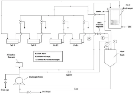
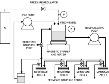
Figure 3.1- Schematic of experimental pressure cell used in the testing of membranes in dead end filtration ... 40
Figure 3.2- Schematic of cross flow filtration apparatus used in the testing of membranes in cross flow conditions. ... 41
Figure 3.3- Schematic of a filtration cell used in the testing of membranes in cross flow conditions. ... 41
Figure 3.4 - Fluid flow of dead-end and cross-flow filtration. ... 42
Figure 3.5 - METcell cross-flow testing apparatus. ... 42
Figure 3.6- Chromatogram of Oligomers Separation ... 43
Figure 4.1- Rejection performance of 18 wt% PI membranes prepared from DMF/1,4-DIOXANE solvent mixture in a ratio (A) 3/1 (B) 1/1 ... 48
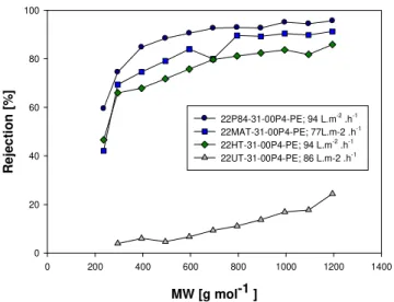
Figure 4.2- Rejection performance of 22 wt% PI membranes prepared from DMF/1,4-DIOXANE solvent mixtures in a ratio 3/1. ... 49
Figure 4.3- SEM pictures of the membranes (A) 18P84-3/1-00P4-PET (B) 18MAT-31-00P4-PET (C) 18HT-31-00P4-PET membrane (D) 18UT-18HT-31-00P4-PET. ... 51
Figure 4.4 - SEM pictures of the membranes.(A) 18P84-11-00P4-PET (B) 18MAT-11-00P4-PET (C) 18HT-11-00P4-PET (D) 18UT-18HT-11-00P4-PET . ... 51
Figure 4.5 - SEM pictures of the membranes.(A) 18P84-13-00P4-PET (B) 18MAT-13-00P4-PET (C) 18UT-13-00P4-PET. ... 52
Figure 4.6 - Rejection performance of wt% 22PI membranes prepared from NMP/THF solvent mixture in a ratio: (A) 3/1 and (B) 1/2; 1/1 ... 53
Figure 4.7- SEM pictures of the membranes: (A) 22P84-31-00P4-PET (B) 22MAT-31-00P4-PET (C) 22HT-31-00P4-PE (D) 22UT-22HT-31-00P4-PET ... 55
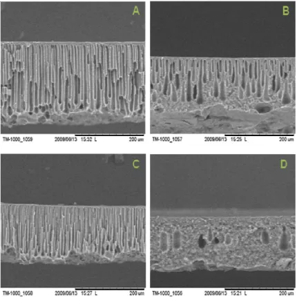
Figure 4.8- SEM pictures of the membranes: (A) 22P84-11-00P4-PET (B) 22MAT-11-00P4-PET (C) 22UT-11-00P4-PET. ... 55
Figure 4.9- SEM pictures of the membrane: (A) 22MAT-12-00P4-PET (B) 22UT-12-00P4-PET ... 55
Figure 4.10 - (A) Rejection performance and (B) Toluene flux profile of 22 wt % P84 membrane prepared from DMSO/ACETONE solvent mixtures in a 3/1 and 5/1 ratio. ... 57
Figure 4.11- SEM pictures of the membranes: (A) 22P84-31-00P4-PET (B) 22MAT-51-00P4-PET ... 58
9
Figure 6.2- Rejection performance and acetone flux profile of membranes casted in different humidity
conditions. ... 69
Figure 6.3- Rejection performance of membranes prepared in different temperatures of coagulation bath. 71
Figure 7.1- Rejection performance of crosslinked PI membranes prepared from DMF/1,4-DIOXANE solvent
mixture in ratio 1/3, 3/1 and 1/1. ... 74
Figure 7.2- Rejection performance of crosslinked PI membranes prepared from NMP/THF solvent mixture
in ratio 3/1. ... 75
Figure 7.3- Rejection performance of crosslinked PI membranes prepared from NMP/THF solvent mixture
in ratio 1/1, 2/1 and 3/1. ... 76
Figure 7.4- FTIR-ATR spectra of non-crosslinked and crosslinked membranes. ... 78
10
List of Tables
Table 1.1 - Examples of polymers used to prepare solvent stable asymmetric membranes. ... 31
Table 3.1 - Molecular weight of commercial polyimides and polyetherimides ... 39
Table 3.2 - Molecular Weight from individual species identified in the standards PS580 and PS 1050. ... 44
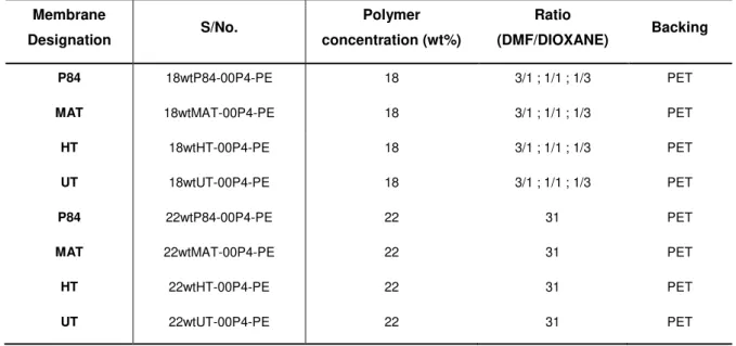
Table 4.1- Characteristics of the membranes prepared from commercially available polyimides and polyetherimides. ... 48
Table 4.2 - Characteristics of the membranes prepared from commercially available polyimides and polyetherimides. ... 53
Table 4.3- Characteristics of the membranes prepared from commercially available polyimides. ... 57
Table 5.1- Molecular masses (M), densities (ρ) and solubility parameters (δ) of solvents used in this Study. ... 62
Table 5.2- Solubility parameters of Solvent mixtures calculated with equation 19. ... 62
Table 5.3- Solubility parameters of Solvent mixtures calculated with equation 20. ... 62
Table 5.4 -Solubility parameter component group contributions ... 63
Table 5.5- ∆δP/S calculated using values of polymers solubility parameters based on group contribution method. Values of ∆δ of solvent mixtures taken from Table 5.3. ... 64
Table 5.6- ∆δP/S calculated using values of polymers solubility parameters based on group contribution method. Values of ∆δ of solvent mixtures taken from Table 5.3. ... 64
Table 5.7- ∆δS/NS. Solubility interaction value between solvent and non-solvent. Using literature value of water solubility parameter and solvent mixtures solubility taken from Table 5.3. ... 65
Table 5.8- ∆δS/NS. Solubility interaction value between solvent and non-solvent. Using literature value of water solubility parameter and solvent mixtures solubility taken from Table 5.3. ... 65
Table 5.9- ∆δS/NS. Solubility interaction value between polymer and non-solvent. Using literature value of water solubility parameter and values of polymers solubility parameters based on group contribution method. ... 65
Table 7.1 - Characteristics of the membranes prepared from commercially available polyimides and polyetherimides. ... 73
Table 7.2 - Characteristics of the membranes prepared from commercially available polyimides and polyetherimides. ... 75
11
Nomenclature
MWCO Molecular Weight Cut Off
OSN Organic Solvent Nanofiltration
MW Molecular Weight
NF Nanofiltration
UF Ultrafiltration
MF Microfiltration
DMF N,N- Dimethylformamide
DMSO Dimethyl sulfoxide
IPA Isopropanol
P84 Polyimide P84 (Lenzing AG)
UT Polyetherimide Ultem 1000
MAT Polyimide Matrimid 5218
HT Polyimide P84 HT
PEG Polyethylene glycol (MW 400 g/mol)
PI Polyimide
PEI Polyether-imide
PAI Polyamide-imide
PES Polyethersulfone
RO Reverse Osmosis
SEM Scanning Electron Microscopy
AFM Atomic Force Microscopy
THF Tetrahydrofuran
NMP N-methyl-2-pyrrolidinone
HDA 1,6-Diaminohexane
PP Polypropylene
12
List of Symbols
∆Π Osmotic pressure difference
∆P Pressure difference
A Area of membrane
t time
Di Fick’s law diffusion coefficient
E Tensile modulus
Fc Capillary force
Fr Resistance of a membrane matrix
Ji Flux
l Membrane thickness
ni Diffusion flux of component i
R Gas constant
r Pore diameter
T Temperature
Tg Glass transition temperature
i Chemical potentials of component i
υi Molar volume
γi Activity coefficients of component i
Cpermeate,Cp,i Concentration of permeate of compound i
Cretentate, Cr,i Concentration of retentate of compound i
Cfeed, Cf,i Concentration of feed of compound i
13
1. Literature Review
1.1 Introduction
Organic Solvent Nanofiltration (OSN) is an emerging, competitive technology for conventional separation
and purification processes such as evaporation, distillation and liquid chromatography. It is being
successfully applied in a variety of chemical processes, e.g. catalyst recovery/reuse, solvent recycling,
chiral separations or ionic liquid separation.5-7
Even though it is a very recent technology, it holds a huge potential because it allows separation of organic
mixtures in a molecular level by only applying pressure and working usually at mild temperatures. At this
molecular level, where rejection occurs, interactions between solvent and solute, solute and membrane and
solvent and membrane are also important in membrane performance. The main challenge for the
expansion of organic solvent nanofiltration membranes is the development of membranes that are stable in
a wide range of organic solvents which present both high solvent permeabilities and adequate rejections for
molecules in the 200-1000 g mol-1 molar mass range.1
A significant step towards the efficient application of reverse osmosis and nanofiltration was the
development of asymmetric type membranes. These membranes, which are capable of very high filtration
rates, were first developed by Loeb and Sourirajan from cellulose acetate for water desalination. Phase
inversion method was introduced for the first time for preparation reverse osmosis (RO) membranes from
cellulose-acetate/acetone/water system.8
In phase inversion process, a polymer solution is transformed from a liquid into a solid state. The process
of solidification initiates with transition from one liquid state into two liquids (liquid-liquid demixing). At a
certain stage during demixing, one of the liquid phases (with higher polymer concentration) will solidify and
then the solid matrix is formed. There are several techniques based on phase inversion concept.
Immersion precipitation is the most often chosen technique.9,15,18,19
Improvement of polymer membranes applicable in OSN is required and relevant trends in this field include
preparation of novel “tailored” polymer membranes with well-defined molecular weight cut off (MWCO)-
14
1.2 Membrane Separation Processes
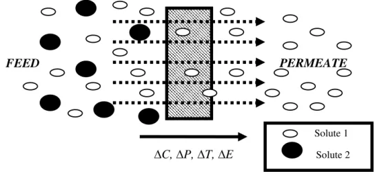
Membrane processes are characterized by the fact that the feed stream is divided into two streams, into
retentate or concentrate stream and the permeate stream. Either of these streams can be the ‘product’ of
the process.1
Figure 1.1- Schematic representation of membrane separation process1.
Membrane itself is the central part of every process and is understood as a selective barrier between two
phases. Transport through the membrane takes place because of the differences in physical or/and
chemical properties between the membrane and the permeating components.2
Figure 1.2- Schematic representation of two phases system separated by a membrane1.
Driving force for the transport of species across the membrane is required and rarely such driving forces
occur alone, it is often the result of a combination. Driving forces are usually in the forms of the potential
gradient, pressure gradient, electric potential gradient or temperature gradient (∆C, ∆P, ∆T, ∆E).
The performance or efficiency of a given membrane is determined by two parameters; its flux and
permeation rate through the membrane. In fact, the nature of the membrane (its structure and material)
determines the type of application ranging from the separation of microscopic particles to the separation of
molecules of an identical size or shape.
C, P, T, E
FEED
PERMEATE
Solute 1
15
Figure 1.3- Range and pressure in various pressure driven membrane processes89.
Reverse osmosis, Nanofiltration, Ultrafiltration and Microfiltration are related processes differing principally
in terms of the size of the molecules it retains.The flux through the membrane is approximately inversely
proportional to the membrane thickness.3
1.2.1 Microfiltration (MF) and Ultrafiltration (UF)
MF and UF are pressure-dependent processes, which remove dissolved solids and other substances from
the fluid (liquid or gas) to a lesser extent than Nanofiltration and Reverse Osmosis. MF membranes have
larger pores in the range of 0.1-10 µm, while UF membranes generally present pore diameters from 0.01
µm to 0.1 µm. The smaller the nominal pore size, the higher the removal capability. Microporous
membranes remove all bacteria and other microbial cells, large colloids, blood cells, yeast and very large
and soluble macromolecules3. This kind of membranes can be implemented in many different water
treatment processes when particles with a diameter greater than 0.1 mm need to be removed from a
liquid1. Examples of Microfiltration applications are:
- Cold sterilisation of beverages and pharmaceuticals;
10-3 – 10-2 10-4 – 10-3
10-2 – 10-1
16
- Clearing of fruit juice, wines and beer;
- Separation of bacteria from water (biological wastewater treatment);
- Effluent treatment;
- Separation of oil/ water emulsions;
- Pre-treatment of water for Nanofiltration or Reverse Osmosis;
- Solid-liquid separation for pharmacies or food industries;
UF membranes retain suspended solids and solutes of high molecular weight (103 - 106 Da) while water
and low molecular weight solutes pass through the membrane.4 This separations process is used in
industry and research for purifying and concentrating macromolecular solutions. UF can also be applied for
pre-treatment of water for Nanofiltration or Reverse Osmosis. Pre-treatment of water is very important
when these filtration techniques are applied, because membrane fouling can easily disturb the purification
process. Pre-treatment is not only important for Nanofiltration and Reverse Osmosis processes, but also for
the above-mentioned microfiltration and ultra filtration processes.
Most materials that are used in UF are polymeric and are naturally hydrophobic. Common polymeric
materials used in UF include: Polysulfone (PS), Polyethersulfone (PES), Polypropylene (PP), or
Polyvinylidenefluoride (PVDF).4
Examples of fields where ultra filtration is applied are:
· The dairy industry (milk, cheese)
· The food industry (proteins)
· The metal industry (oil/ water emulsions separation, paint treatment)
· The textile industry
1.2.2 Nanofiltration (NF) and Reverse Osmosis (RO)
NF and RO are used when low molecular weight solutes such as inorganic salts or small organic molecules
have to be separated from the solvent. In comparison of UF with NF/RO, denser membranes are required
with a higher hydrodynamic resistance and as a consequence to the latter, a much higher pressure must
be applied to force the same amount of solvent through the membrane. The pressure used in reverse
osmosis ranges from 20 to 100 bar; in nanofiltration, from about 10 to 30 bar.4,1,10
Currently, in RO and NF applications, very thin membranes are used. They have a thin active non-porous
layer and a porous supporting layer that gives the membrane mechanical stability.10 This support layer
gives the membrane protection from breaking or ripping. The active layer is responsible for the membrane’s
selectivity and for nearly all resistance to mass transport. The membranes displaying this combination of an
active layer and a support structure are called asymmetric membranes. Membranes applied in NF/RO that
are mostly asymmetric have asymmetric structure with a dense top layer (thickness<1 µm) supported by a
17
NF is a technique mainly applied for the removal of organic substances, such as micro pollutants and
multivalent ions because it usually have high rejections to most dissolved organic solutes with molecular
weights above 100-200 g.mol-1 and good salt rejection at concentrations below 1000-2000 ppm salt.
RO is the process of forcing a solvent from a region of high solute concentration through a membrane to a
region of low solute concentration by applying a pressure in excess of the osmotic pressure. This is the
reverse of the normal osmosis process, which is the natural movement of solvent from an area of low
solute concentration, through a membrane, to an area of high solute concentration when no external
pressure is applied. This process is best known for its use in desalination (removing the salt from sea water
to get fresh water), but has also purified naturally occurring freshwater for medical and industrial
processes.11,12
Almost all RO membranes are made from polymers, cellulose acetate and polyamide. They are generally
composite or asymmetric membranes, as it was refereed before, and the support material is commonly
polysulfone while the thin film is made from various types of polyamines.11
1.2.3 Organic Solvent Nanofiltration
Nanofiltration (NF) is a membrane separation process in which small molecules like antibiotics, dyes,
vegetable oils or catalysts are removed from a mixture. Previously the research has been mainly focused
on aqueous systems. In recent years, NF has found applications in organic solvents like acetones, esters,
alkanes, aromatics.
OSN is a membrane separation process which use requires solvent-resistant membranes that preserve
their separation characteristics under more aggressive conditions of strongly swelling solvents and
elevated temperatures. This membrane filtration technology uses either polymeric or inorganic membranes
that cover molecular weight cut-offs in the range 200 to 1000 Da.
Studies have shown the high stability of OSN membranes in commonly applied organic solvents such as
acetone or toluene. Crosslinking of OSN membranes has been shown to achieve stability of the
membranes even in a harsh environment of polar protic solvents such as N,N-dimethylformamide. OSN
membranes are reported to be suitable for a broad range of applications including chiral separation of drug
intermediates, homogeneous catalyst recovery or monomer separation from oligomers.
In recent years, there has been an increase in interest in polyimide (PI) and polyetherimides (PEI) as a
suitable polymer for manufacturing OSN membranes, as they show excellent thermal and chemical stability
in a wide range of organic solvents.15,16,69,77 Commercially available PI membranes, STARMEMTM
(W.R.Grace & CO., USA), have been widely used in several OSN applications. The STARMEMTM series of
18
Organic Solvent Nanofiltration (OSN) is a new field of membrane technology of a great interest to industry.
It shows potential applications ranging from petro-chemistry to pharmaceutical industry. The main
advantages associated with the use of OSN are:
- Process simplification
- Mild processing conditions
- Energy savings
- Product recovery
1.3 Membrane Preparation
1.3.1 Membranes Types
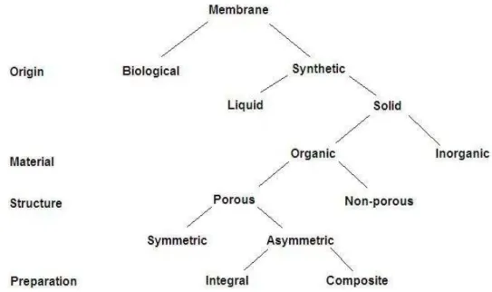
Membrane can be classified according to nature, i.e., biological or synthetic membranes. This is an
essential first distinction since the two types of membranes differ completely in structure and functionality.
The latter can be subdivided into living and non-living membranes.
Synthetic membranes can be subdivided into organic (polymeric or liquid) and inorganic (ceramic, metal)
membranes.13 Another means of classifying membranes is by morphology or structure. This is also a very
illustrative route because the membrane structure determines the separation mechanism and hence the
application. Organic membranes can be classified into two main groups: open porous membranes, which
are applied in microfiltration and ultrafiltration, and the dense nonporous membranes, applied in gas
separation and pervaporation.1 If we confine ourselves to porous organic membranes, two types of
membranes may be distinguished, i.e. symmetric or asymmetric membranes. Furthermore, depending on
the method of preparation, asymmetric polymer membranes can be either integral, when the whole
structure is prepared within the same step from the same material, or composite, in which case the
membrane consists of different layers.13
19
1.3.2 Membranes Materials
Choosing the proper materials for a specific membrane is also very important. The selection of a material
for OSN membranes can be based on the next characteristics: film forming properties, chemical and
thermal stability, commercial availability and price, and affinity for the components in the feed.
Generally membrane materials can be classified into three types: synthetic polymers (e.g. polyethylene,
polypropylene, polyamides, polysulphones, polycarbonates, polyimides), modified natural products (e.g.
cellulose, rubber, wool) and miscellaneous (e.g. ceramic, inorganic, liquid). A good membrane material is
chemically resistant, thermally and mechanically stable, and has a high selectivity and permeability.8 Since
this project revolves around polymeric membranes, these will be discussed in more detail.
Polymeric membranes generally fail to maintain their physical integrity in organic solvents because of their
tendency to swell or dissolve. However, it is possible to obtain UF or NF membranes for non-aqueous use
by preparing them from polymer materials that are more solvent resistant. Polyimides meet these
expectations. In the literature, asymmetric aromatic polyimide membranes, which can withstand high
pressure, high temperature, and organic solvents were successfully prepared and applied in UF and NF
processes. It can be obtained denser membranes for nanofiltration by adding additives - either volatile
solvents such as acetone, tetrahydrofuran, 1,4-dioxane, or diethyleneglycol dimethylether (DGDE).15;16,17
Also, some researchers have indicated that polyimides have great potential as the next generation of
membrane materials because of their good gas-transport properties, thermal and mechanical properties,
and chemical stability.
1.3.3 Synthetic Membranes Preparation
The type of membrane depends mainly on the material used and the kind of technique employed. There
are a number of different techniques available to prepare polymeric membranes such as sintering, track
etching, stretching and phase inversion.1,2
1.3.3.1 Phase inversion
In phase inversion process, a polymer solution is transformed from a liquid into a solid state. The process
of solidification initiates with transition from one liquid state into two liquids (liquid-liquid demixing). At a
certain stage during demixing, a solid polymer-rich phase(with higher polymer concentration) will solidify
forming the solid matrix and a liquid polymer-poor phase will form the pores the membrane.23 This phase
separation concept can be induced by several methods:15,18,19
Immersion precipitation: Immersion of cast polymer into a coagulation bath of the non-solvent. The solvent exchange leads to the precipitation of the polymer. Most of the membranes prepared commercially are
20
Thermal precipitation: The solvent quality decrease when the temperature is lowered. After demixing is induced, the solvent is removed by extraction, evaporation or freeze drying.21
Solvent evaporation: Polymer is dissolved in a mixture of volatile solvent and less volatile non-solvent. During the evaporation of the solvent, the solubility of the polymer decreases and the phase separation can
occur. In solvent evaporation, an important aspect is the temperature of the casting solution
Precipitation from the vapour phase: Casting the polymer solution in an environment saturated with the non-solvent. This prevents evaporation of the solvent and precipitation takes place when the non-solvent
vapour penetrates into the solution.20
Phase inversion, developed by Loeb and Sourirajan in the early sixties, became one of the most adaptable,
economical and reproducible formation mechanisms for the polymeric asymmetric membranes. These
membranes for water desalination were first prepared from cellulose-acetate/acetone/water system19. The
key for high performance is the very thin skin-layer which makes a high selectivity and permeability
possible. Membranes made by the Loeb-Sourirajan technique involve the precipitation of casting solution
by immersion-precipitation 9, 18.
Figure 1.5- Schematic asymmetric polymeric membrane30.
The most common technique used commercially to produce asymmetric membrane is phase inversion via
immersion precipitation22, so this work will mainly focus on this technique.
1.3.3.2 Immersion-precipitation
The polymer is dissolved in an appropriate solvent or mixture of solvents and it is formed the solution
usually named dope solution or casting solution (10-30 wt%). Then the dope solution is cast on a
supporting layer (backing), for example non-woven polyester or polypropylene, by means of a knife. The
casting thickness varies from 50 to 500µm.The process follows with the polymer film immersed into a
coagulation bath consisting of a nonsolvent (usually water).Water adsorption and loss of solvent cause the
film to rapidly precipitate from the top surface down. A casting solution consisting of only one phase is
precipitated into two phases: a solid, polymer-rich phase that forms the matrix of the membrane and liquid,
polymer-poor phase that forms the membrane pores9,15,77.
21
Figure 1.6- Schematic drawing depicting the principle of immersion-precipitation technique1.
1.3.3.3 Liquid-liquid demixing
The thermodynamic behaviour of a polymer solution subjected to immersion precipitation can be
represented in a polymer/solvent/non-solvent phase diagram. In the phase diagrams, three types of phase
separation behaviour can be identified: liquid-liquid demixing, solid-solid demixing and solid-liquid
demixing. However it is the liquid-liquid demixing that plays a central role in the generation of the required
morphology.
There are two mechanisms well known for liquid-liquid demixing: nucleation and growth (NG) and spinodal
decomposition (SD).20 NG occurs when the polymer system departs from the homogeneous and stable
region to the metastable region which is located in the spinodal and binodal lines in the phase diagram. SD,
the less frequent mechanism, occurs when the system enters an unstable region which is located between
the polymer-non-solvent axis and spinodal in the phase diagram. Again, two different phases are formed,
but instead of developing well-defined nuclei, two co-continuous phases will be formed.
1.3.3.4 Ternary system
In the ternary diagram the corners of the triangle represents the pure components, polymer, solvent and
nonsolvent80. A point located on one side of the triangle represents a mixture consisting of two corner
components although any point inside the triangle represents a mixture of the three components. The tie
lines connect points on the binodal that are in equilibrium, one end of these tie lines is rich in polymer and
the other one is poor in polymer. The initial procedure for membrane formation based on these ternary
diagrams is always to prepare a homogeneous (thermodynamically stable) polymer solution. In fact, most
of the commercial phase inversion membranes are prepared from multi-component mixtures, but in order to
22
Figure 1.7- Schematic representation of a ternary system with a liquid-liquid demixing gap25.
In the region (I) of the diagram there is the initial polymer solution in stable. Metastable region (II) is
between binodal and spinodal curve and there is where the polymer solution ‘phase separates’ into a
polymer-lean and polymer-rich phase. Region (III) represents unstable, two-phase region.
Strathmann et al.25 present the process of the membrane formation as a line through phase diagram. As
demonstrated in figure 1.7, during membrane formation the system changes from a composition A, this
represents the initial casting solution, to a composition D, which represents the final membrane. At
composition D, two phases are in equilibrium, a solid (polymer-rich) phase which forms the membrane
structure and a liquid (polymer-poor) phase, which constitutes the membrane pores filled with nonsolvent.
The entire phase inversion process follows the path from A to D in which the solvent is exchanged by the
nonsolvent.25 Point B indicates the concentration at which the precipitation begins.
At some point, the viscosity is high enough for the precipitated polymer to be regarded as a solid. This
composition is presented as point C on polymer-non-solvent axis and determines the overall morphology of
the membrane24.
Although this theory assumes a precipitation path as a single line representing the average composition of
the whole membrane which is not completely correct because the rate of precipitation and the precipitation
path represented through the phase diagram differ throughout the membrane layer, from the dense top
layer to the porous bottom of the membrane. Secondly, the precipitation process does not follow a
determinate path.
Ternary diagram is separated into a homogeneous phase and an area representing the demixing gap (area
23
reported in literature the interaction parameters studied give an indication of the size and location of this
demixing gap.
The polymer solvent interactions may be determined using swelling measurements. The solvent
non-solvent interactions can be calculated from the activities and the polymer non-solvent interaction can be
determined from osmometry measurements. The Flory Huggins parameter may be estimated using the
Hildebrand solubility parameter80,82.
Phase diagrams can predict whether or not a solution of a certain solvent is suitable for membrane
formation.
1.3.4 Membrane Morphology
1.3.4.1 Skin formation
When the cast film is immersed in the coagulation bath it initiates an exchange between the solvent and
nonsolvent. At the surface of the film, the concentration of the solvent quickly reaches a value rendering
phase separation to start. Underneath the top layer, the nonsolvent concentration is too low to induce
phase separation. For that reason, phase separation first takes place at the surface of the film resulting in
an increase of the polymer concentration in the surface layer. Obtained dense skin layer hinders further flux
of nonsolvent into and solvent out of the immersed polymer film.
A formation of a dense skin layer is favoured when following factors apply:
- a higher initial polymer concentration of the casting solution, which favours the conditions for a larger super saturation in the top layer prior to nucleation;
- a lower tendency of the nonsolvent to diffuse into the top layer delays nucleation till sufficient solvent depletion of high polymer concentration has been obtained;
- lower temperature of the coagulation bath increases the super saturation resulting in a decreased growth kinetics of nuclei formed30.
Structure of the top layer is strictly dependent on the diffusion ratio of solvent to nonsolvent.31 The ratio can
be thus expressed by the equation:
1 2
n
n
k
=
Equation 1where
n
1 andn
2are the diffusion flux of nonsolvent and solvent, respectively. When the k value of the skinlayer is large due to rapid diffusion of solvent into a coagulation bath or low rate of nonsolvent diffusion into
24
top layer caused by solvent depletion and net movement of the polymer in the direction perpendicular to
the surface induced by a very steep gradient of the polymer chemical potential at the surface of the film.
When the k value of the top layer is not large enough, a porous top layer is formed. The following diffusion
rate of the sublayer is only slightly affected by the top layer due to its high porosity and big pore size.
If the top layer only limits the diffusion of nonsolvent, then the k value of the sublayer is large as in the case
of the skin layer and the composition path of the sublayer, as it enters the solidification region resulting in
dense structure formations.31
To obtain integrally skinned asymmetric membranes dry/wet method is widely applied. Here, prior to
immersion in the coagulation bath, evaporation of solvent is allowed. This results in an increase of polymer
concentration in the top layer. When the solvent in the casting solution has a high boiling point, elevated
temperatures are necessary to obtain a dense skin layer. To avoid the high temperatures during the
evaporation step, more volatile solvents such as acetone, tetrahydrofuran (THF), 1,4-dioxane, can be
added to the casting solution. White et al. prepared membranes with PI/NMP/THF solutions69.
1.3.4.2 Skin of Nanofiltration membranes
The microstructure of nanofiltration polymer membranes typically consists of a dense nanoporous top layer
of several tens to hundreds of nanometers which gradually evolves into a meso and microporous region.
Although the determination of the pore size of the top layer is not the only property description needed to
understand the transport mechanism through the nanofiltration membranes, it is considered one of the
most important ones. The most common technique used to estimate the size of the nano-pores is
cross-flow filtration measurements. By using specific molecules with different molecular weight and fitting their
retention curves in function of the permeate flux a molecular weight cut-off (MWCO) is calculated.
There is no universal definition of MWCO however, most often it is defined by plotting the rejection of
solutes versus their molecular weight, and interpolating this data to find molecular weight corresponding to
the 90% rejection83.
1.3.4.3 Membrane Morphology from Immersion Precipitation
According with Kimmerle and Strathmann51, there are five structural elements in the morphology of
membranes prepared by immersion precipitation: macrovoids, nodules, cellular structures, bi-continuous
structures and unconnected latex.
Macrovoids
Two types of structures can be obtained in the sub layer of asymmetrical membranes, one is sponge-like
25
of the membrane thickness. The presence of macrovoids is undesirable, in general, because they may lead
to a weak spot in the membrane which is to be avoided especially when high pressure is applied, i.e, they
cause mechanical weakness in the membrane.1 Most of the techniques that can be used to delay the onset
of demixing will also result in the disappearance of macrovoids and includes increasing the viscosity of
polymer solution.31,36
Nodules
Nodules are partly fused spherical beads with a diameter of approximately 25-200 µm and results from a
very rapid precipitation conditions during membrane formation37. They are frequently observed in the dense
top layer of the membranes. While the theory of nodule formation is disputed,37 two aspects have been
established: (i) The diffusion process of solvent and non-solvent are rapid compared to the mobility of the
polymer molecules; (ii) Nodules occur in thin surface layers of high polymer concentration.
Cellular Structures
These structures are present in most membranes prepared by delayed precipitation. Broens et al.49 have
shown that the formation of such structure is the result of the nucleation and growth of the polymer poor
phase. The delay time for demixing is important and under rapid demixing (<1 sec.)21, the membranes
formed will have a thin top layer and a sub-layer with macrovoids. If the delay time is slow (few seconds to
minutes), the membranes will have a dense and thick top layer due to the high concentration of the polymer
solution at the onset of demixing. The porosity and degree of interconnectivity between the pores will also
be low 50.The speed of demixing depends on the mass transfer in solution as well as the thermodynamics
of the system as described by the phase diagrams 22.
Bi-continuous morphologies
Membranes with bi-continuous morphologies have a highly interconnected pore structure or contain a layer
with a highly interconnected pore structure. These formations can be due to spinodal decomposition or can
be the result of coalescence of polymer poor droplets generated by bimodal decomposition.1
1.3.4.4 Polymeric membrane drawbacks
Furthermore, some factors affect the membrane performance significantly and should be avoided when
possible. These are called limiting factors and are explained as follows.
Concentration-polarization
Concentration polarization is most common in pressure- driven membrane separations where it can reduce
the flux of molecules through the membrane. Concentration polarization occurs when the dissolved
molecule is being rejected and accumulate in front of the membrane, causing its concentration at the
26
With all polarisation phenomena (concentration, temperature polarization), the flux at a finite time is always
less than the original value. When steady state conditions have been attained a further decrease in flux will
not be observed.1In the laboratory, increasing the turbulence of the feed fluid controls concentration
polarization, this is achieved by stirring.
A typical concentration figure for the rejected component is shown in figure 1.8.
Figure1.8- Concentration-Polarisation31.
Compaction
Compaction is the mechanical deformation of a polymeric membrane matrix present in pressure-driven
membrane processes. Compaction causes collapse of a porous structure of the membrane thus reducing
the effective pore size of the membrane and permeate flux.22After relaxation, the flux will generally not
return to its original value since the deformation process is often irreversible. The extent to which
compaction occurs is dependent on the applied pressure and membrane morphology.
Membrane Fouling
Membrane fouling is the effect caused by the accumulation of feed constituents at the membrane surface
leading to their adsorption and this is often observed when solutions containing biological materials (e.g.
proteins, macromolecules or microorganisms) and their metabolic products have to be processed.
Restoration of membrane performance may be possible in some cases through cleaning. However this
may not be possible in cases where fouling results in changes to the membrane structure.
Anti-foulants and pre-treatment technologies might be integrated into the system to prevent/reduce the
effects of fouling39. A source of practical membrane anti-foulants, pre-treatment strategies may be found in
the Membrane filtration handbook for aqueous systems.53
Membrane fouling is influenced by the chemical nature of the membrane material and the feed solution
27
1.3.4.5 Parameters influencing performance and morphology of OSN membranes
There are several key factors during membrane fabrication that influence the membrane morphology.
These variations are true for most polymers used to prepare membranes. Factors such as the use of
additives, the temperature of casting solution and the evaporation time also change the morphology of the
membranes and may indirectly change the separation performance of membranes, i.e, control the cut-off
performance of membranes. The factors are:
Choice of solvent/non-solvent system: Selection of a particular system in order to prepare membranes by immersion precipitation, the polymer must be soluble in the solvent and the solvent and the non-solvent
(e.g. water) must be completely miscible.1Many polymers can be dissolved in aprotic solvents i.e
N,N-dimethylformamide (DMF); N-methyl-2-pyrrolidinone (NMP);Dimethyl sulfoxide (DMSO) and others. This
miscibility of the components is described by the free energy of mixing.
When the solvent and non-solvent get lower affinity there is a reduction in the gradient of the tie lines in two
phase region in the ternary diagram. Mixtures that have high affinity e.g. DMF result in instantaneous
demixing forming the morphology with a thin top layer with macrovoid24,54. Conversely if there is low affinity
between the mixtures then this will delay the onset of demixing forming the dense and thick top layer. A
way to delay the onset of demixing is to add solvent to the coagulation bath1.
Polymer concentration: The polymer concentration in the casting solution has a significant effect on membrane structure and properties. A low polymer concentration in the casting solution tends to favour the
formation of finger like structures whilst a high concentration favours the sponge like structures24. The
polymer concentration can also alter the performance of the membranes, where several authors
demonstrated that permeability decreases with higher selectivity as polymer concentration in the casting
solution increases1,23,47. However, the increasing of initial polymer concentration in the casting solution
leads to concentrated zone in the polymer film/non-solvent interface favouring the sponge likes structures.
Composition of coagulation bath: The composition of the coagulation bath (non-solvent) may also influence the type of morphology produced. The composition of solvent in the coagulation bath can be used to switch
from a porous to a nonporous membrane.1 Deshmukh and Li55 showed this experimentally using a
PVDF/DMAc/water system and changing the ethanol:water content in the coagulation bath. As the ethanol
concentration in water bath was increased from 0% to 50%, the long finger like structure near the outer wall
of the fibre slowly changed through a short finger-like structure to a sponge-like structure.
Composition of the casting solutions: The addition of volatile co-solvent (e.g. Dioxane, Acetone and Tetrahydrofuran (THF)) to casting solutions offers an alternative method to modify the selectivity of
asymmetric membranes1,47,56. By allowing partial evaporation of co-solvent between casting and immersion
precipitation step, a skin-layer with elevated polymer concentration can be formed. This densified skin-layer
28
slowing down the diffusion of solvent and non-solvent. Casting membrane from polymer solution with an
optimal co-solvent and solvent ratio allows forming an asymmetric membrane with a defect free top,
ultra-thin and dense skin-layer on top of a highly porous sub-layer with sponge-like structure. Successful control
over the MWCO of membranes fabricated from polyimide (PI) 57and polyether-imide (PEI) through variation
of the ratio between solvent and co-solvent in the dope solution are demonstrated.
Also non-solvent may be added to the casting solution to affect the type of morphology of the membrane.
The amount of non-solvent added must be in the homogeneous region such that demixing does not occur,
which means that the composition must be in the one-phase region in the ternary diagram where all the
components are completely miscible with each other. As with the case of changing the composition of the
coagulation bath, changing the composition of the casting solution has a similar effect.
Other relevant parameters which´s may influence polymeric membranes performance and
morphology.
There are several other key factors, in addition to the complex formulation of the casting solution that also
influence the final structure of the membranes after immersion process and may indirectly change the
separation performance of membranes. They include:
- Temperature of coagulation medium
- Evaporation time
Temperature of coagulation medium: Increasing coagulation bath temperature obviously enhances the exchange rate of solvent and non-solvent, resulting in membranes with higher porosities and more
macrovoids by numbers and sizes1. However, several opposing observations are reported. A significant
loss in permeability and slight decrease in rejections are observed with increasing medium temperature
using PES membranes.58 Whereas, an increasing medium temperature promotes salts rejection of PAN
membranes. Concomitantly with the presence of inorganic additives, higher temperature promotes the
formation of an interconnected pore structure and hence providing higher permeation rate59.
Evaporation time: Similar to addition of co-solvent into the casting solution, increasing the evaporation time before phase immersion forms a skin-layer with elevated polymer concentration and hence inducing a
delayed in the demixing time.1,60 This forms membrane with a dense top-layer and whilst reduces the
permeability and giving a higher selectivity as shown for PI47,61, PEI and CA 50 membranes. Evaporation is
often achieved by forcing a convective air flow over the cast film or by allowing the film to evaporate in the
air freely. Several factors such as evaporation time, temperature and relative air humidity must be taken
into consideration to achieve a controlled process. In parallel to the higher rejections, the macrovoids
29
1.3.4.6 Post treatment
Post treatments are often introduced into membrane fabrication processes to improve the separation
performance, long-term stability and also to provide a reproducible, reliable and easy hand-able
membranes at large scale. The crucial role of post-treatment membranes has often been over-looked and
not explicitly reported in literature. The post-treatment frequently used are: thermal annealing, crosslinking,
drying and conditioning and others.
1.3.4.7 Crosslinking of Membranes
In order to increase the membranes chemical, mechanical and thermal stability, these can be crosslinked.
However, this is often at the expense of a decrease in permeability. Crosslinking gives the membrane the
solvent resistant characteristics. Most significantly, this causes the polymers to become insoluble.
A number of strategies for crosslinking the PI-based membranes have been proposed including the use of
radical initiated (thermally or via the use of UV) and chemical crosslinking62.Post casting modification of
polymer films provides the easiest method of manipulation as this allows the desired morphology of the
membranes to be attained via phase inversion followed in aggressive conditions.
As for OSN the membrane stability of the under layer is as critical as the separating layer due to solvent
permeation, effective crosslinking of the whole membrane must be achieved. Several chemical crosslinking
strategies for use in membranes have been proposed and include the inclusion of condensable crosslinking
sites during polymer preparation and the use of di/poly-amines in a ring opening reaction62.
1.4 Transport Models
The selective control of the permeation rate of different species is the most important property of the
membranes. The transport of the species through the membrane is principally controlled by driving force
and whether the membrane exhibits active or passive transport properties. Chemical potential gradient is
the driving force and is a result of pressure, temperature, concentration difference or electromotive force. 42-44
There are two main models commonly used describing the membranes transport mechanism: pore flow
model developed by Sourirajan and Matsuura and solution-diffusion model proposed by Lonsdale et al 45,
modified later by Wijmans and Baker.41
30
1.4.1 Pore-flow model
The pore flow model is used to describe the permeation through porous membranes (ultrafiltration,
microfiltration).It assumes that solvent transport occurs by pressure-driven convective flow through pores in
the membranes. Separation of different permeants is achieved based on size exclusion, the incompatibility
of molecule parameters such size, shape and charge, with the pores in the membrane.
Phase inverted membranes have a structure similar to a system of closely packed spheres.25 In such
cases, the Hagen-Poiseuille equation is modified for spheres to give the Carmen Kozeny equation:
x P S K J ∆ ∆ − ⋅ ⋅ ⋅
= 23 2
) 1 ( ε η
ε Equation 2
In this equation J is solvent flux, K the Kozeny constant, ε the porosity, S the surface area per unit volume,
∆P the differential pressure across the membrane, η liquid viscosity and ∆x the membrane thickness.
1.4.2 Solution-diffusion model
The solution-diffusion model became a more applied model to describe transport through pore-less
membranes, especially in RO, pervaporation and gas permeation in polymer films. This model assumes
that the permeating species dissolves in the membrane and diffuses through it, down a concentration
gradient. Separation is achieved due to differences in the amount that dissolves in the membrane and the
rate at which it diffuse through the membrane.
The solution diffusion model gives the following simplified expression for the solvent flux:
(
π
)
υ
υ
∆
−
∆
≈
−
−
−
=
P
T
R
l
c
K
D
T
R
p
p
l
c
K
D
J
i i i i i i i i i i0 0
0
(
)
exp
1
Equation 3For the case of the solute, the term
−
υ
i(
p
0−
p
i)
R
T
is small and equation 3 may be reduced to:(
j jl)
S D(
j jl)
i i
j
c
c
B
c
c
l
K
D
J
=
0−
=
− 0−
Equation 4Where cj0 is the bulk solute concentration (no concentration polarisation) in the feed stream, Cjl the solute
31
1.5 Organic Solvent Nanofiltration (OSN)
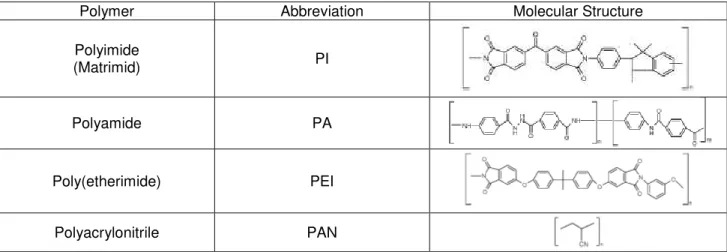
1.5.1 OSN membranes materials
In OSN membranes, polymeric and ceramic are utilized as a major materials. Two types of polymeric
membranes can be distinguished: integrally-skinned asymmetric membranes and composite membranes.
It is required that a polymer to prepare OSN membranes exhibits outstanding thermal and chemical stability
in an environment of organic solvent. It is know that Polyimides (PI) meet these requirements.
The chemical resistance and high selectivity of the type of polymers available in the market make polymeric
membranes still relevant for the scientist community. The polymer itself should be ideally chemically,
thermally and mechanically stable for forming OSN membranes. Solvent stability of the polymeric
membrane is often related to the chemical structure of the polymer and the presence of certain structural
elements, e.g. aromatics groups, imide bonds. Generally, copolymerization also induces rigid segments
which impart solvent resistance. The table 1.1 shows some polymers that have been used to prepare
solvent stable asymmetric via immersion precipitation.
Table 1.1 - Examples of polymers used to prepare solvent stable asymmetric membranes.
Polymer Abbreviation Molecular Structure
Polyimide
(Matrimid) PI
Polyamide PA
Poly(etherimide) PEI
Polyacrylonitrile PAN
The advantage of high selectivity and chemical resistance of the type of polymers available in the market
make polymeric membranes still relevant for many scientists. Many chemically stable polymer types such
as polyacrylonitrile (PAN), polyimide, polyether-imide (PEI), polyamide-imide (PAI), polyethersulfone (PES),
cellulose acetate (CA) and etc. have been used to prepare solvent stable asymmetric NF and/or RO
membrane via immersion precipitation.
Recently, many scientists have been integrating blends of different types of polymer to modify membranes
for better performance. Blending is simply an economic method used to combine favourable properties
32
successfully demonstrate the enhancement of polyimide (PI) based pervaporation membranes selectivity
by blending a hydrophobic polymer with a highly hydrophilic polymer
1.5.2 Polyimides
Figure 1.9- Aromatic polyimide repeatable unit14.
Polyimide (PI) belong to the important class of organic materials know as ‘high performance’ polymers
because of their exceptionally high thermo-oxidative stability’. The structural composition of aromatics
polyimides consists of heterocyclic imide and aryl groups, which are linked sequentially by simple atoms or
groups.
1.5.3 Commercially available polyimides
Commercial polyimide (PI) OSN membranes have been show to give good performances in several
organic solvents (e.g. toluene, methanol, ethyl acetate etc. ) but are however unstable in amines and have
generally poor stability and performance in polar aprotic solvents such as methylene chloride (DCM),
tetrahydrofuran (THF), N,N-dimethyl formamide (DMF) and n-methyl pyrrolidone (NMP) in which most of
these membranes are soluble.
Chemically crosslinked PI membranes are reported to withstand even an aggressive solvent such as
N,N-dimethylformamide (DMF).
Commercial polyimide materials which are commonly used to prepare OSN membranes include:
- Matrimid-5218 (Ciba Geigy Corp., USA) is a copolymer of
5(6)-amino-1-(4’aminophenyl)-1,3-trimethylindane and 3,3’-4,4’-benzophenonetetracarboxylic dianhydride
-Lenzing P84 (HP Polymers, Austria) is a copolymer of 3,3’-4,4’-benzophenonetetracarboxylic dianhydride
and a mixture of di(4-amino-phenyl)methane and toluenediamine.
Both polymer types were reported to show outstanding chemical resistance, economically viable flux and
high rejection of hydrocarbon species in polar and non-polar organic solvent systems. However, most of
33
1.5.4 Characterisation Techniques used for Nanofiltration Membranes
1.5.4.1 Membrane performance
Membranes are usually characterized by the solvent flux and molecular weight cut-off (MWCO).
The flux (J) or permeation rate is obtained by measuring the volume of permeate per unit area of the
membrane per unit time, using the following equation:
= t A V J Flux m P
,
Equation 5
The MWCO defined as the molecular weight of the molecule that is 90% rejected by the membrane.
MWCO is interpolated from a plot of rejection versus the MW of the test compounds. The rejections(R)
percentages are calculated following the equation
% 100 1 (%) , , × − = i R i p i C C ejection
R
Equation 6
The concentrations are taken from permeate, after steady state achieved, and retentate solution. The
values are calculated through HPLC analysis.
1.5.4.2 Membrane Structure
Surface analysis techniques can be used to characterise the chemical nature of the membrane surface,
which may necessary for the investigation of solution adsorption, solute-membrane interaction or chemical
changes after chemical post-treatment.
Microscopy methods are widely used to determine the membrane morphology, especially Scanning
Electron Microscopy (SEM) in the NF membrane industry. SEM only gives qualitative information about the
membrane morphology and an estimation of the membrane skin thickness, because the resolution is not
high enough to visualise the pores in the skin of an asymmetric NF membrane.
FESEM (Field Emission Scanning Electron Microscopy) has a much better resolution, of about 1 nm. For
FESEM as well as for SEM, membranes have to be dried and coated with charge conducting layer, with a
thickness of the order of nm, which is also the size of the pores in the membrane. This might cause
problems in interpreting the obtained electron micrographs.
TEM (Transmission Electron Microscopy) of dried membranes has a higher resolution (< 1nm ), but often
34
ATM (Atomic Force Microscopy) is method used to characterize the surface morphology of a membrane. In
general, this technique does not reveal the possible position and size of a pore, but it is an indication of
surface roughness or corrugations.
FTIR-ATR (Fourier Transform Infrared Spectroscopy – Attenuated Total Reflectance) is one of the most
common techniques described in literature to chemically analyse the surface of the polymeric membrane.
1.5.5 Applications of OSN membranes
When membranes achieved good stability and performance in organic solvents, pressure driven membrane
separation can be integrated in organic processes such as: products recovery; solvent exchange; organic
solvent purification (in order to reuse them).
Examples of OSN practical applications are:
1. Homogenous catalyst separation (separation of homogeneous transition metal complexes from the
reaction products and solvents);
2. Edible oil processing (removal of phospholipids and pigments (“degumming”), extraction solvent
recovery and deacidification of the oil);
3. Processes in petrochemical industry (dewaxing process, production of high quality aromatics, removal of
sulphur);
4. Processes in pharmaceutical industry (concentration of antibiotics or pharmaceutical intermediates out of
organic solvents, recovery of solvents used in preparative HPLC, solvent exchange is in pharmaceutical
synthesis chains).
1.5.6 Challenges in OSN
OSN membrane technology application is still challenging and there are many issues that need to be
addressed and understood. Improvements and advances in OSN membrane technology must be
introduced to further expand this new technology into many areas of the industry. The key issues to be
addressed to provide a regulatory-compliant chemical resistant membrane element include:
- Membranes with improved chemical stability in a broad range of organic solvents
- Membranes with a higher fidelity for separation between molecules
- Membrane components that provide excellent solvent, thermal and mechanical stability