Universidade de Aveiro 2013
Departamento de Química
Ana João
Vicente Correia
Automontagem de péptidos para formação de
biomateriais nanofibrais
I Universidade de Aveiro 2013 Departamento de Química
Ana João
Vicente Correia
Automontagem de péptidos para formação de
biomateriais nanofibrais
Peptide self-assembly for nanofibre biomaterials
Dissertação apresentada à Universidade de Aveiro para cumprimento dos requisitos necessários à obtenção do grau de Mestre em Bioquímica, ramo de Bioquímica Clínica, realizada sob a orientação científica do Doutor Maxim Ryadnov , Investigador Principal no National Physical Laboratory, Doutor Angelo Bella, Investigador Auxiliar no National Physical Laboratory e Doutor Professor Pedro Domingues, Professor Auxiliar do Departamento de Química da Universidade de Aveiro
Este trabalho foi financiado pela FCT, União Europeia, QREN, FEDER e COMPETE (PEst-C/QUI/UI0062/2013)
III
“Nothing in life is to be feared, it is only to be understood. Now is the time to understand more, so that we may fear less" Marie Curie
V
o júri
Presidente Prof. Dr.ª Rita Maria Pinho Ferreira
professora auxiliar convidada do Departamento de Química da Universidade de Aveiro
Prof. Dr. Pedro Miguel Dimas Neves Domingues
professor auxiliar do Departamento de Química da Universidade de Aveiro
Dr. Maxim Ryadnov
investigador principal no National Physical Laboratoy – United Kingdom
Dr.ª Alisa Rudnitskaya
investigadora auxiliar do Departamento de Química da Universidade de Aveiro
Dr. Angelo Bella
VII
Acknowledgments I would like to express my sincere gratitude to my supervisor Dr. Max Ryadnov from the National Physical Laboratory for all the help
and support given during my research for this thesis. I extend my thanks also to my co- supervisor Dr Angelo Bella who expertise was indispensable to the outcome of this work. I am also extremely grateful to Professor Pedro Domingues from Aveiro University for invaluable help throughout this endeavour. I would also thanks to Lloyd Ryan for his patience when helping me with the set-up process in the laboratory. Thanks to Adelina Pereira for edited this thesis.
A word of gratitude to my friend Fátima Santos for being there for me when the going got tough.
Thanks to my parents, Armando Correia and Armandina Correia and my sister Tatiana Correia for their unequivocal support and loving.
Last but not least, my most thanks to Pedro Filipe for his unfaltering support. I could not have it without him.
palavras-chave Biomateriais, péptido-amfifílico, auto-montagem, regeneração de tecidos
resumo Ao longo da última década, o processo de auto-montagem peptídica têm
suscitado considerável interesse pela sua capacidade de gerar novos biomateriais com diversas aplicações, incluindo a regeneração de tecidos e cosméticos. Biomateriais com base peptídica são agrupados de baixo para cima a partir de pequenos blocos de construção. O presente estudo concentra-se na utilização de diferentes motivos estruturais peptídicos para a construção de biomateriais fibrosos. Neste trabalho, diferentes péptidos amfifílicos foram sintetizados utilizando o processo de síntese peptídica do estado sólido para formar distintas estruturais peptídicas. A capacidade de auto-montagem e propriedades biológicos foram caracterizados utilizando dicroismo circular, espectroscopia, microscopia electrónica de transmissão e determinada a concentração mínima inibitória. Os espectros de dicroísmo circular revelaram bobina aleatória e conformações β-folha para as estruturas amfifílicas. A maioria das imagens de TEM revelou estruturas fibrais à nanoescala e foi observada alguma atividade antimicrobiana. Efetivamente, os resultados demonstram que os péptidos sintetizados possuem capacidades de auto-montagem para formarem supraestruturas nanofibras, não revelando no entanto fortes propriedades antimicrobianas. Este trabalho apresenta novos designs de biomateriais com potenciais aplicações em reparação de tecidos através da capacidade de formação de nanofibras
keywords Biomaterials, peptide-amphiphile, self-assembly, tissue regeneration
abstract Over the last decade self-assembling peptide systems have attracted
considerable interest as novel biomaterials for use in different applications including tissue regeneration and cosmetics. Peptide-based biomaterials are assembled from small building blocks from the bottom up. This study is focused on the use of different peptide folding motifs as building blocks for the construction of fibrous biomaterials. Different peptide amphiphiles (PAs) were synthesized using solid phase synthesis and their folding, self-assembly and biological properties were characterized using circular dichroism (CD) spectroscopy, transmission electron microscopy (TEM) and minimal inhibitory concentration (MIC) assays. CD spectra showed random coil and β-sheet conformations for the amphiphiles. TEM revealed nanoscale fibre structures for most of the PA’s, some of which displayed antimicrobial activity. Effectively, the results demonstrate that the designed peptide self-assembles into nanofibre suprastructures. However, the peptides were not strongly antimicrobial and formed fibrillar structures. This work introduces new biomaterial designs with potential applications as nanofibre scaffolds for tissue engineering.
Table of contents
Ackonwledgments Resumo Abstract Table of contents Table of figures Table of abbreviationChapter 1 – Introduction
1 1.1 - Biomaterials 11.2 – Peptide – based biomaterials 1
1.3 – Peptide self-assembly 3
1.3.1 – Features of peptides used as building blocks 3
1.3.2 – Proteins folding motifs 4
1.3.2.1 – α- helix and β-sheet 4
1.3.2.2 - Collagen 7
1.4 – α-helix and coiled-cloil based biomaterials 11
1.4.1 – Design principles 11
1.4.2 – Assemblies based on coiled coil 13
1.5 – Peptide-amphiphile – based biomaterials 17
1.6 – Aim and objectives 20
Chapter 2 – Materials and Methods
212.1 – Soild Phase peptide Synthesis 21
2.1.1 – Soild support 22
2.1.2 - Linkers 23
2.1.3 – Fmoc an Boc strategy in solid phase peptide synthesis 24
2.1.4 – Coupling methods 25
2.2 – Characterization of crude peptides 26
2.2.1 – Coupling High Performance Liquid Chromatography (HPLC) to a Mass Spectrometer ( MS) 26 2.2.2 – Circular Dichroism (CD) 27 2.3 - Experimental 29 2.3.1 – Materials 29 2.3.2 - Methods 30
2.3.2.1 – General Peptide Synthesis 30
2.3.2.2 – Fmoc and Boc deprotection 30
2.3.2.3 – Cleavage of MBHA rink amide resins and removal of protection groups 31
2.3.2 – RP-HPLC 31
2.3.3 – Circular Dichroism 31
2.3.4 – Transmission Electron Microscopy 32
2.3.5 – Antibacterial activity 32
Chapter 3 – Self-Assembly of peptide-amphiphile
333.1 - Introduction 33
3.2 – Results and discussion 34
3.2.1 – α-helix – amphiphile structure 34
3.2.2 – Peptide-amphiphile structure 40
General conclusion and future work 52
Table of figures
Figure 1.1: Examples of protein structural motifs, schematics (top) and transmission electron micrographs (bottom).
Figure 1.2: a) Schematic representation of amino acids. R is the side chain specific to each amino acids (b) Peptide bond (amide bond) between two amino acids. The amide bond is a chemical covalent bond that results from the reaction between the carboxyl group of an amino acid and the amine group of another.
Figure 1.3: a) Structure of α-helix displaying the hydrogen bond between N-H group and CO group. Representation of 3.6 residues per turn . b) Model protein classes.
Figure 1.4: Structures of parallel and anti parallel β-sheet which show the difference in hydrogen bond patterns.
Figure 1.5: The peptide sequence and self-assembled material. Peptides with DPro-LPro adopt β-hairpin conformation and TEM revealed entangled fibrils with a width of 3 nm each. Peptides with LPro-LPro adopted extended β-strand conformation and TEM revealed fibrils.
Figure 1.6:a ) Molecular structure of collagen-like peptide (Ac-Pro-Hyp-Gly-HH3)
triple helix. b) The molecular surface.
Figure 1.7: Structural Hierarchy of Collagen.
Figure 1.8: a) Amino acid sequence of collagen-mimetic peptide indicating the distinct domains found in its structure. b) Interhelical electrostatic interactions yielding triple-helical protomers.
Figure 1.9: High magnification transmission electron micrographs reveal a well defined periodic structure.
Figure 1.10: Global parameters of a coiled-coil structure.
Figure 1.11: Schematic side view representations of two–stranded parallel and antiparallel coiled coils. The residues of one helix are labelled a-g, while those of the other helix are marked a`- g`. a) Illustration of a parallel coiled coil showing both N termini. Potential interactions between g´and e residues are indicated. b) Representation of an antiparallel coiled coil where the N terminus is shown on the left and C terminus on the right. Potential interaction between g`and g residues.
Figure 1.13: a ) The peptide sequence of SAF-p1 and SAF-p2a comprised of two blocks each. A and B blocks for SAF-p1 and C and D blocks for SAF-p 2a. b ) B complements C and A complements D. This connection results in a sticky-ended dimer. Figure 1.14: The discontinuous design of a) CCNN and b) DDCC peptide. β-alanine causes a kinked structure rather than a straight one because of the flexibility induced by this residue.
Figure 1.15: TEM of a) Straight fibres formed between SAF-p1 and SAF-p2a in 1:1
ratio. b) Fibres formed by adding CCNN peptide to SAF-p1/SAF-p2a in 1:1:1 ratio. c) Fibres formed by adding DDCC peptide to SAFp1/SAF-p2a in 0,01:1:1 ratio.
Figure 1.16: Chemical structure of peptide-amphiphile. Region 1 is a hydrophobic segment with 16 carbons. Region 2 consists of four consecutive cysteines. Region 3 is a flexible linker with 3 glycines. Region 4 is a single phosphorylated serine. Region 5 shows the cell adhesion ligand ( RGD).
Figure 1.17: Self-assembly of PA in the form of a cylindrical micelle.
Figure 1.18: Sequence of PA1. The molecule includes a hydrophobic region (C16), a
glycine region and a charged headgroup.
Figure 1.19: a) Cryo-TEM Images of PA1. This peptide-amphiphile forms nanofibres. b) PA 9 with N-methylated glycine in position 1. This peptide-amphiphile forms spherical micelles.
Figure 2.1: Solid Phase Peptide Synthesis. The green square is a temporary protecting group of an amino group, X, Y and Z are side chains and the red circle depicts a side chain protecting group.
Figure 2.2: Occurrence of polymerization between styrene and DVB. Figure 2.3: Synthesis of MBHA resin.
Figure 2.4: Deprotection process using TFA.
Figure 2.5: Hydroxybenzotriazole and derivative additive (top) and uronium salts (below). Figure 2.6: MALDI-TOF with reflectron.
Figure 2.7: CD instrumentation.
Figure 2.8: Representative CD spectra for α-helix (blue line), β-sheet (red line) and random coil (black line).
Figure 3.1: Lipoprotein design: a) Peptide sequence used in the study b) schematic of micelle structure
Figure 3.2: CD spectra at 20º C for AC1 at 50 µM (black line), 100µM (red line), 200 µ (blue line) in 10 mM MOPS.
Figure 3.3: CD spectra for peptide AC1 at 10º C (black line) and at 90º C (red line) in 10 mM MOPS.
Figure 3.4: Negatively stained transmission electron micrographs of peptide AC1. Assembly conditions in 10 µM MOPS at pH 7.4, left overnight at 20° C (top) and at melting (below)
Figure 3.5: Antimicrobial activity for Escherichia coli at 4.5 hours and 24 hours. Each value was done in duplicate.
Figure 3.6: Antimicrobial activity for Pseudomonas aeruginosa at 4.5 hours and 24 hours. Each value was done in duplicate.
Figure 3.7: Antimicrobial activity for Staphylococcus aureus at 4.5 hours and 24 hours. Each value was done in duplicate.
Figure 3.8: Peptide –amphiphile types used in the study
Figure 3.9: CD spectra at 20° C for peptide AC3 at 50 µM (black line), 100µM (red line), 200 µ (blue line)
Figure 3.10: CD spectra at 20° C for peptide AC4 at 50 µM (black line), 100µM (red line), 200 µM (blue line )
Figure 3.11: CD spectra at 20° C for peptide AC5 at 50 µM (black line), 100µM (red line), 200 µM (blue line)
Figure 3.12: Negatively stained transmission electron micrographs of peptide AC3. Assembly conditions in 10 µM MOPS at pH 7.4 left overnight 20° C.
Figure 3.13: Negatively stained transmission electron micrographs of peptide AC4 (top) and peptide AC5 (below). Assembly conditions in 10 µM MOPS at pH 7.4 left overnight at 20° C.
Figure 3.14: PA types used in the study.
Figure 3.15: CD spectra at 20ºC for AC6 at 50 µM (black line), 100µM (red line), 200 µM (blue line)
Figure 3.16: CD spectra at 20ºC for peptide AC7 at 50 µM (black line), 100µM (red line), 200 µM (blue line)
Figure 3.17: CD spectra at 20ºC for peptide AC8 at 50 µM (black line), 100µM (red line), 200 µM (blue line )
Figure 3.18: CD spectra at 20° C for peptide AC9 at 50 µM (black line), 100µM (red line), 200 µM (blue line)
Figure 3.19: Negatively stained transmission electron micrographs of peptide AC6 (top) and peptide AC7 (below). Assembly conditions in 10 µM MOPS at pH 7.4 left overnight at 20° C.
Figure 3.20: Negatively stained transmission electron micrographs of peptide AC8 (top) and peptide AC 9 (below). Assembly conditions in 10 µM MOPS at pH 7.4 left overnight at 20° C.
xix
Table of abbreviation
ESE - European Society for Biomaterials
FACIT - fibril associated collagens
TEM - Transmission Electron Microscopy
SAF - self-assembling fibers
PA - peptide-amphiphile
CD - circular dichroism
FT-IR - Fourier transform infrared spectroscopy
PA – Peptide – amphiphile
MOPS - 3-(N-morpholino)propanesulfonic acid
DIPEA – dilauryphosphatidyglycerol
EDT – 1,2-Ethanedithiol
HCTU–(2-(6-Chloro-1H-benzotriazole-1-yl)-1,1,3,3-tetramethylamininum hexafluorophosphate)
HBTU - O-Benzotriazole-N,N,N’,N’-tetramethyl-uronium-hexafluoro-phosphate
TBTU - O-(Benzotriazol-1-yl)-N,N,N',N'-tetramethyluronium tetrafluoroborate
RP HPLC – Reverse Phase- High Performance Liquid Chromatography
MS – Mass Spectrometer
MALDI ToF – Matrix assited laser desorption ionization time- of- fight
MIC – Minimal inhibitory concentration
Pbf – 2,2,4,6,7-pentamethylbenzofuran-5-sulfonyl
TFA- trifluoroacetic acid
TIS – triisopropyl silane
xx
PEGA - Polyethylene Glycol Polyacrylamide
CLEAR - cross-linked ethoxylate acrylate
PEG - polyethylene glycol
DVB – divinylbenzene DMF- dimethylformamide DMC – dichloromethane MBHA – methylbenzhydrlamnine Fmoc - 9H-fluoren-9-ylmethoxycarbonyl Boc - tert-butyolxycarbonyl HOBt – Hydroxybenzotriazole HOAt - 1-hydroxy-7-azabenzotriazole UV – ultraviolet TCEP - tris(2-carboxyethyl)phosphine
1
Chapter 1 - Introduction
1.1 - Biomaterials
In 1976, the European Society for Biomaterials (ESE) defined a biomaterial as “a nonviable material used in a medical device, intended to interact with biological systems” (1, 2 ). However, the current definition put forward for a biomaterial is “a material intended to interface with biological systems to evaluate, treat, augment or replace any tissue, organ or function of the body (3 ,4). Biomaterials have been investigated because of their many potential biological functions, such as releasing polypeptide growth factors, blocking antibody permeation and serving as matrices to guide tissue regeneration (3,5).
Biomaterials have become a promising area of research with successful applications in medicine and bioengineering (6). Different chemical systems have been developed as biomaterials, including synthetic polymers, and recently, molecular design based on biological structure. Polymeric biomaterials with inorganic systems have been used in tissue engineering, particularly in orthopaedic research (7). Hydrogels differ from most biomaterials as they do not dissolve in water and have also found use for biomedical applications (3).
1.2 - Peptide-based biomaterials
Complementary strategies can be used in the fabrication of molecular biomaterials. These materials can be generated by stripping down or molecule-by-molecule assembly (5, 6). However, molecular self-assembly is considered to be the most powerful approach in the fabrication of novel materials. Peptides self-organize to form a distinct structure with a specific functionality (8). For this reason, this process has been exploited for the production of synthetic material where proteins are versatile building blocks for fabricating materials.
2
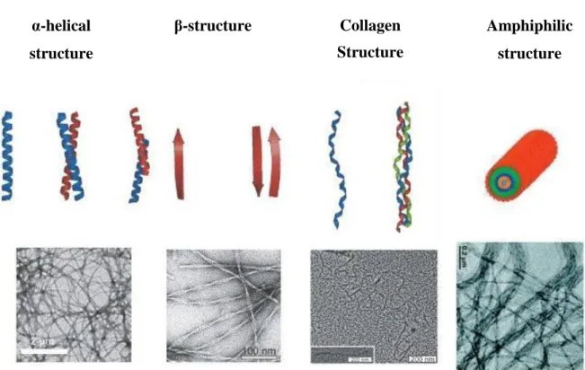
Much research has been focused on self-assembling peptides that produce supramolecular structures with very distinct features. Different structural motifs can be used as self-assembling building blocks. For example, α-helix, β-sheet, collagen and amphiphilic peptides have been shown to give different supramolecular morphologies (Figure 1.1). Other examples include ionic self-complementary peptides, which is a type of surfactant-like peptide, surface nano-coating peptides and molecular switches (6). All these structures can be cross-linked together to form fibrous structures. α-helical structure β-structure Collagen Structure Amphiphilic structure
Figure 1.1: Examples of protein structural motifs, schematics (top) and transmission electron micrographs (bottom) (6).
3
Biomaterials play an important role in many activities, for example, as matrices to guide tissue repair, and in the stimulation of a vascularization response releasing growth factors (9). In the future biomaterials will assume an important role in medicine and be used in a wide variety of non-medical applications through biological design and the incorporation of dynamic behaviour (10). For these reasons the study of these peptide-based materials is a promising field of research and of interest for use in the fabrication of different materials for a wide range of applications.
1.3 – Peptide self-assembly
1.3.1- Features of peptides used as building blocks
The molecular arrangement of peptide materials has been investigated over the past years (10). Their molecular structures may be constituted by biological, organic and/or inorganic compounds (10). For this reason, understanding molecular structure is a crucial step when building a new biomaterial.
Self-assembly is a process in which biological entities (building blocks) are spontaneously organized to form a supramolecular structure (11, 12). However, this mechanism displays special interactions that enable the construction of a novel material (13). The driving forces of molecular self-assembling are non-covalent interactions, such as hydrophobic, ionic, Van der Walls forces and hydrogen bonds, which are essential for the specific association between different building blocks. Among the building blocks used are short peptides (12).
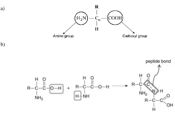
Peptides are polymers of α-amino acids connected through peptide bond (amide bond) (Figure 1.2b) (8). The bond formation occurs between the carboxyl and the amide group present in all natural amino acids. An amide bond is formed between two amino acids through the release of a water molecule where the α-carbon is a chiral centre asymmetric (Figure 1.2a) (8). What characterizes each of these molecules is the variable group R side chain, which provides different properties and biological functions. In nature there are 20 amino acids. These are divided into polar and non-polar structures, as well as according to charge (positive or negative) (8).
4
a)
b)
Figure 1.2: a) Schematic representation of amino acids. R is the side chain specific to each amino acids (2) b)Peptide bond (amide bond) between two amino acids (2). The amide bond is a chemical covalent bond that results from the reaction between the carboxyl group of an amino acid and the amine group of another.
1.3.2- Protein folding motifs
1.3.2.1 –α-helix and β-sheet
The mechanism by which the protein folds to form different structures is not yet fully understood (14, 15). Knowing how the amino acid sequence interacts to form a 3-D structure is a crucial to understanding their contribution to the protein folding process (16) There are two main folding motifs in proteins: α-helices and β- sheets (17).
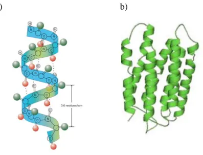
The α-helix structure is characterized by hydrogen bonds between the N-H group of an amino acid (α) and its C=O group (i +4, i+7), as seen in figure 1.3. Generically, it could be described as the coiling of the amino acid sequence around a
5
virtual axis. Experimental measurements indicated a periodicity of 3.6 amino acids per helical turn (figure 3) (18).
a) b)
Figure 1.3: a) Structure of α-helix display the hydrogen bond between N-H group and CO group. Representation of 3.6 residues per turn (3) . b) Model protein classes (16).
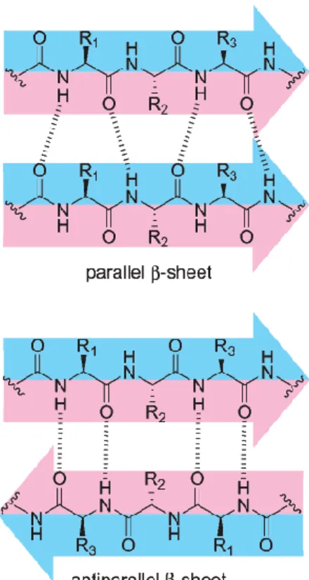
The β-sheet structure consists of different β-strands laterally connected by hydrogen bonds between their NH and C=O groups along the peptide/protein backbone- (19). The type of arrangement and relationship between the sequential strands is defined by hydrogen bonds. In a parallel arrangement, all strands are oriented in the same direction (Figure 1.4). However, when the orientation of the strands is opposite an antiparallel β sheet is formed (Figure 1.4) (19). The torsion angles that β-sheet can adopt depend on the type of the side chain formed by amino acid residues.
The formation of parallel β sheet in protein aggregation is associated with some neurodegenerative diseases like Alzheimer’s, Parkinson’s and prior disease (19, 20). Many researchers have sought to understand the factors that lead to amyloid formations, such as protein sequence and environment conditions. Other studies have focused their investigation on the variety of β-sheets that derive from amyloid protein (21).
6
Figure 1.4: Structures of parallel and anti parallel β-sheet which show the difference in hydrogen bond patterns. (19)
The secondary structure of peptide molecules has gained considerable interest among researchers who work in the field of self-assembly (21). The β-sheet can be a fundamental element of a building block for nanomaterials using proteins (22). Consequently, the importance of this secondary structure is currently being investigated due to its potential for the development of a new structure design for various applications. Lorraine et al studied four peptides and have proposed designs that bring about the formation of β-sheet at the air-water interface (23). They quantified the intermolecular interactions that take place between phase behaviours, which allowed these researchers to explore the relationship of self-assembly and its role in the production of composite biomaterials (23).
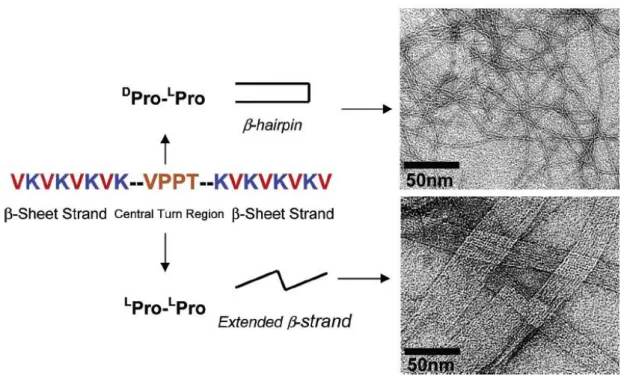
Matthew et al, on the other hand, have designed a new peptide with two β-sheets containing hydrophobic valine and hydrophilic lysine residues in alternation (14). The central sequence contains diproline translated as Pro-Pro, which opens up conformation and supports trans linkage. The DPro-LPro sequence undergoes intermolecular folding and adopts a β-hairpin conformation, which self-assembles as
7
β-sheet-rich hydrogels. Contrarily, peptide with an L
Pro-LPro sequence adopts an extended β-strand and self-assembles as amyloid fibril. Figure 1.5 shows both folded peptides along the fibril axis translated as formation of intermolecular β-sheet hydrogen and extended β-strand. These structures exhibit characteristics similar to those of amyloid fibril, which, when assembled, are stable at different Ph levels and temperatures (14).
Figure 1.5: The peptide sequence and self-assembled material. Peptides with DPro-LPro adopt β-hairpin conformation and TEM revealed entangled fibrils with a widhth of 3 nm each. Peptides with LPro-LPro adopted extended β-strand conformation and TEM revealed fibrils (14).
1.3.2.2 – Collagen
Collagen, which exhibits very characteristic folding, is the most prevalent protein in the animal kingdom (24). This protein is located at diverse sites with specific functions, playing a key role in maintaining tissue and cellular size and shape (25). Because of this key structural feature, collagens have acquired significant interest within the scientific community (26).
8
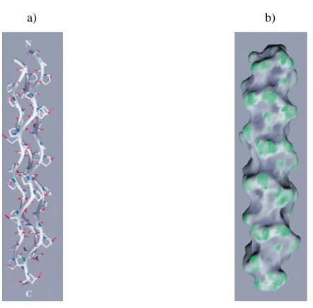
The structure of collagen was determined by X-Ray diffraction over 50 years ago. It is characterized by a triple helix with three different polypeptide chains (α-helix) that are combined to fold together to the left (27,29). Amino acid composition consists of a repeated tripeptide with a X Y Gly sequence, in which Proline (Pro) and hydroxyproline (Hyp) are predominant in the X and Y positions, respectively (Figure 1.6) (28, 30). The latter amino acids (Pro and Hyp) help to stabilize the triple helix, while glycine (Gly) facilitates hydrogen bonding and intermolecular cross-link.
a) b)
Figure 1.6: a ) Molecular structure of collagen - like peptide (Ac-Pro-Hyp-Gly-HH3) triple helix (28). b) The molecular surface (28)
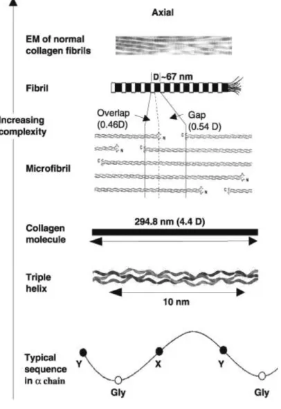
The collagen self-assembly has not been fully understood, but several methods describe this process like a periodic fibrilar assembly (31). Some studies have indicated that fibers consist in building blocks with periodicities (29). Three peptide chains forming the triple helical collagen molecule of 294, 8 nm in length and 1,5 nm in diameter (24). Hydrophobic and electrostatic interactions are involved in the arrangement of the collagen monomers where several molecules form a microfibril. These microfibrils have been suggested that to be the building blocks of fibril with a
9
67 nm (D-period) periodicity axial (24). The figure 1.7 shows the hierarchical organization of collagen.
Figure 1.7: Structural Hierarchy of Collagen (29).
Nearly 30 types of collagen proteins were identified and described with different structures, organization and localization (30). These are characterized by a complex structure, splice variants, self-assembly ability and several biological functionalities. Collagen can be classified as fibril-forming collagens, microfibrillar collagens, anchoring fibrils, hexagonal network forming collagens, fibril associated collagens (FACIT), transmembrane collagens and multiplexins (31).
Rele et al have described the solid phase synthesis of collagen-mimetic triple helix peptide promoters (32). According to these authors, the primary sequence
10
comprises three different X Y Gly domains, where the Pro-Hyp-Gly central core is flanked with Glu ( negative charged) or Arg ( positive charged) peptide repetition (Figure 1.8a). The presence of strong electrostatic and hydrogen bonds between staggered positions allows the formation of thermodynamic stable complexes (Figure 8b).
a)
b)
Figure 1.8: a) Amino acid sequence of collagen-mimetic peptide indicating the distinct domains found in its structure. b) Interhelical electrostatic interactions yielding triple-helical protomers (32).
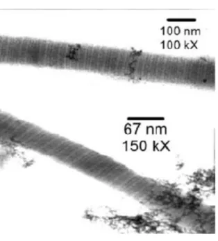
Figure 1.9 shows a Transmission Electron Microscopy (TEM) image of a synthetic peptide which was self-assembled into a periodic fibrous structure. After a long period of incubation the formation of ~70 nm diameter uniform micron-length fibres was observed. The capacity to design periodic elements into reliable assemblies can facilitate fabrication and tailored ordered materials for several applications.
11
Figure 1.9: High magnification transmission electron micrographs reveal a well defined periodic structure (32).
1.4– α-helix and coiled coil–based biomaterials
In reality, the coiled coils domain is present in several proteins that play important biological functions. The examples of these proteins are transcription factors, muscle myosin, tumour suppressors and cytoskeleton proteins. For this reason, coiled coil domains have attracted special interest for use in the design of new synthetic peptides.
1.4.1 –Design principles
The coiled coil structure was originally observed in native proteins (33). This structure consists of two or more α-helixes that are wound into a superhelix (34, 35). Coiled coil is characterized by the distance of a full-turn of the superhelix (“pitch”), by the angle between the helix and its axis (“pitch angle”) and the angle between two neighbouring helices (“helix-crossing angle”) (36). Figure 1.10 shows the global parameters of a coiled-coil.
12
Figure 1.10: Global parameters of a coiled-coil structure [37].
Usually α-helix requires 3.6 amino acids per turn. However, a coiled coil helix shifts to the left and accommodates 3.5 residues per turn (18). This allows the repetition of side chains after every sequence of seven residues. The design of coiled coil peptides is based on heptad repeats. The heptad amino acids are also named
abcdefg, where a and d are hydrophobic, e and g are positions often occupied by
charged amino acids, and the remaining amino acids are generally hydrophilic residues (35, 36). Hydrophobic residues have an important role in structure stability during the self-assembly process, forming the helix interface, while the amino acids in e and g positions allow electrostatic recognition (33).
The α-helices can be combined to form parallel or antiparallel homodimers or heterodimers. (34). The orientation of coiled coil helices is determined by the interaction between the two heptads residues (33). Figure 1.11 shows amino acid repetition and illustrates the two different orientations that can be found between α-helix in a coiled coil. In a parallel coiled coil the residues in d position of one α-α-helix interacts with the amino acids of the neighbouring α-helix in the same position. (37). On the other hand, in a antiparallel coiled coil the α-helix runs in the opposite direction to that of a parallel coiled coil, which means that the residues found at d position interact with the amino acid found at a position. These different orientations have been exploited to design several synthetic peptides.
13
a) b)
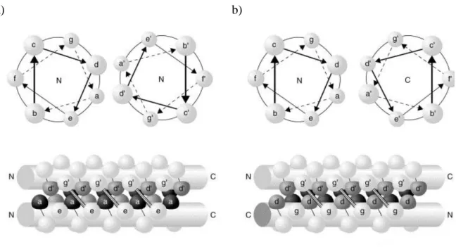
Figure 1.11: Schematic side view representations of two–stranded parallel and antiparallel coiled coils.
The residues of one helix are labelled a-g, while those of the other helix are marked a`- g`. a) Illustration of a parallel coiled coil showing both N termini. Potential interactions between g´ and e
residues are indicated. b) Representation of an antiparallel coiled coil where the N termini is shown on the left and C terminus on the right. Potential interaction between g` and g residues (38).
1.4.2. – Assemblies based on coiled-coil
The success in the development of novel designed molecules from spontaneously peptide-based building blocks has motivated further research in molecular design. The design of a coiled coil covers every type of structure from parallel and antiparallel homodimers to parallel and antiparallel heterodimers (39). Most peptides with self-assembly capacity described in literature use a solid phase peptide synthesis technique as it is very efficient (40, 41). In light of this, some researchers have sought to design α-helix coiled coil with the ability to grow and form fibrous aggregates (42, 43).
Many works suggest that α-helix coiled coil plays an important role in the promotion of peptide self-assembly. Woolfson and co-workers described peptides based on parallel folding of a coiled coil, which allows for the understanding of the
14
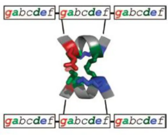
design principles of self-assembly in peptide systems (36, 39). The peptides the authors investigated consisted of heptad repeats with isoleucine and leucine in hydrophobic positions a and d, respectively. The research group introduced glutamates and lysines in g and d positions to allow the occurrence of ionic interactions. (Figure1.12). The resulting fibres were straight, rod-shaped and micro in length.
Figure 1.12: Dimeric coiled coil heptad with specific residues at g, a, d and e positions (36).
Dong et al described four coiled coil peptides which are differentiated by the amino acids found at b, c and f positions (44). These particular amino acids were selected with the aim to form a dimeric coiled coil. The researchers demonstrated that nanofibres are formed when the concentration of a peptide increases. In addition, they observed that introduction of positive charge residues at b, c and f positions results in the appearance of nanofibres with diameters of 4 nm. On the other hand, in the absence of positive charge residues self-assembly created fibres 20 or more nanometres in diameter. This observation led to the creation of an alternative mechanism for self-assembly.
In previous works Woolfson et al introduced the concept of self-assembling fibres (SAF)(45). This system comprises a design with two complementary de novo leucine-zipper peptides that form a sticky ended heterodimer (46). Each peptide is 28 residues-long that assemble and mix to form fibres. The mature SAF samples were
15
prepared with a mixture of SAF-p1 and SAF-p2 (39). The primary sequence of these is characterized by heptad repeat, HPPHPPP, where H is hydrophobic and P polar residues. Ryadnov et al applied the SAF concept to produce heterodimers in a parallel coiled coil (47). SAF peptides have different subunits, namely A and B domains in SAF-p1 and C and D regions in SAF-p2. Thus, A and D regions complement each other, whilst B is complementary to C (Figure 1.13b). In this investigation, SAF-p2 was re-designed as SAF-p2a because the latter interacted better and more efficiently with SAF-p1 (see Figure 1.13a). This combination improved affinity between the two protofibrils, and resulted in the formation of straight fibrils, as shown in Figure 1.15a.
a
b
Figure 1.13: a) The peptide sequence of SAF-p1 and SAF-p2a comprised of two blocks each. A and B blocks for SAF-p1 and C and D blocks for SAF-p2a. b ) B complements C and A complements D. This connection results in a sticky-ended dimer (47).
Another alternative explored by the authors was the introduction of discontinuities into the SAFs fibres, which brought about kinks and splits in the two new peptides CC NN and DD CC, respectively. The CCNN peptide is comprised of two copies of block C linked by the C-termini, while both N-termini remain free. This enabled the interaction between the two blocks. However, the two copies of C blocks are joined by β-alanine to give flexibility to the peptide structure. The DDCC peptide follows a similar principle:
16
two copies of D blocks are linked via N-termini while C-termini remain free. Figure 1.14 schematically shows the conception of both peptides. Due to differences in their sequence blocks, fibres with distinct characteristics were observed (Figure 1.15).
a) b)
Figure 1.14: The discontinuous design of a) CCNN and b) DDCC peptide. β-alanine causes a kinked structure rather than a straight one because of the flexibility induced by this residue (47).
a) b) c)
Figure 1.15: TEM of: a) Straight fibres formed between SAF-p1 and SAF-p2a in 1:1 ratio. b) Fibres formed by adding CCNN peptide to SAF-p1/SAF-p2a in 1:1:1 ratio. c) Fibres formed by adding DDCC peptide to SAFp1/SAF-p2a in 0,01:1:1 ratio (47).
17
1.5- Peptide-Amphiphile
Amphiphilic molecules are constituted by distinct hydrophobic and hydrophilic segments (48). This structure consists of a peptide attached to a hydrophobic alkyl tail. Aliphatic tails in an aqueous solution tend to aggregate, while the peptide portion packs on the surface. It is well known that self-assembly leads to the formation of nanofibres with a structure similar to that of cylindrical micelles (49). This formation is possible due to a number of interactions like dipole-dipole, hydrogen bond, nonspecific van der Walls interaction and hydrophobic force.
Self-assembly of peptide-amphiphile (PA) has raised interest in scaffolding of new biomaterials for many applications (50). Self-assembled PA can adopt various morphologies by choosing different residues and alkanes. Stupp et al have designed a peptide-amphiphile with a hydrophobic tail and a hydrophilic peptide head (Figure 1.16) (51). This peptide was synthesized by standard solid phase chemistry according to the following specific features: 1) four cysteine amino acids were incorporated to form disulfide bonds between adjacent molecules. 2) the serine was phosphorylated at the peptide end to attract calcium and other ions, and to regulate and facilitate the mineralization of hydroxypatite. 3) Arg-Gly-Asp (RGD) sequence was introduced into the peptide to promote cell attachment to the nanofibres. The last of these characteristics would be beneficial for biomedical applications. TEM imaging suggests that assembled peptide-amphiphile forms nanofibres and is stable in an alkaline solution (Figure 1.17).
18
Figure 1.16: Chemical structure of peptide-amphiphile. Region 1 is a hydrophobic segment with 16 carbons. Region 2 consists of four consecutive cysteines. Region 3 is a flexible linker with 3 glycines. Region 4 is a single phosphorylated serine. Region 5 shows the cell adhesion ligand ( RGD) (51).
Figure 1.17:Self-assembly of PA in the form of a cylindrical micelle (51).
Later Hartgerink and co-workers reported a prototypic peptide amphiphile containing 12 amino acids and an alkyl tail with 16 carbons (52). The importance of hydrogen bonds in self-assembly was investigated through a set of 26 PA’s, including 19 N-methylated variants and 7 alanine mutants. PA1 has a linker region (seven glycines) connecting the hydrophobic segment to the head group, which consists of Glu-Arg-Gly-Asp-Ser (ERGDS) sequence (Figure 1.18). The remaining PA consists of peptides with alanine mutations.
19
Figure 1.18: Sequence of PA1. The molecule includes a hydrophobic region (C16), a glycine region and a charged head group (52).
These peptides displaying alanine mutations were analyzed by circular dichroism (CD), Fourier transform infrared spectroscopy (FT-IR) and TEM. It was found that the four amino acids close to the core are critical for self-assembly of PAs into nanofibres. For this reason, by selectively eliminating the key hydrogen it is possible to change the nanostructure resulting from self-assembly. Thus, this study helps to understand the self-assembly mechanism of peptide-amphiphile.
20
1.6 - Aim and objectives
Biomaterials have led to great improvements in many applications due to their specific characteristics. The aim of the present work is to fabricate a new biomaterial with capacity to self-assemble by synthesizing and characterizing a new peptide with different folding.
The specific objectives of this work are:
1. Design and synthesis of a new peptide with different folding using the solid phase peptide synthesis method;
2. Purification using High Performance Liquid Chromatography (HPLC); 3. Biophysical characterization of generated models in aqueous and membrane environments and analysis by circular dichroism (CD)
4. The use of electron transmission microscopy (TEM) to confirm the presence of nanofibres.
21
Chapter 2 - Methods and Materials
2.1-Solid Phase Peptide Synthesis
Solid Phase Peptide Synthesis (SPPS) as conceived and demonstrated by Merrifield can provide oligopeptides and small proteins (53, 54). The strategy is based on the use of amino acid side chain protection and the attachment of a C-terminal amino acid to an insoluble polymeric support (i.e. solid) via a linker (55). Side chains that may be reactive and an α-amino group are protected with temporary protecting groups to avoid them reacting with each other (56). The process starts with the coupling of the first amino acid to the resin followed by the deprotection of the α-amino protecting group. After this a second protected amino acid can be introduced in the growing sequence. This cycle is repeated until the required peptide sequence is assembled. At the end of the synthesis, the protecting groups are removed and the bond between the C-terminal amino acid and the polymeric support is cleaved with a specific reagent (56). Figure 2.1 shows the scheme of solid phase peptide synthesis.
Figure 2.2: Solid Phase Peptide Synthesis. The green square is a temporary protecting group of an amino group, X, Y and Z are side chains and the red circle depicts a side chain protecting group (53).
22
The main advantage of this method is that there are only two reactions, the amide bond formation and deprotection. These require optimization and the use of excess solvents and reagents, as well as the removal of by-products by simple washing (53,57). On the other hand, SPPS has its limitations, namely the number of peptides achievable is restricted (maximum 50 amino acids) and the fact that the method implies the use of a large quantity of expensive solvents (53).
2.1.1 – Solid Support
Different solid supports have been developed over time. The resins normally used as supports are polyethylene glycol polyacrylamide copolymer (PEGA) resin, cross-linked ethoxylate acrylate resin (CLEAR), polyamide resin and polyethylene glycol (PEG) (58). However, of these the most widely used in solid phase synthesis is a cross-linked polymeric resin obtained from the co-polymerization of styrene and divinylbenzene (DVB) (figure 2.2)(58). Polystyrene is a co-polymer of linear vinyl benzene.
23
The quantity of divinylbenzene used for cross-linking is about 1-2% (56). Consequently, this resin has an increased hydrophobicity that can affect the peptide assembly (57).
2.1.2 – Linkers
The choice of linkers depends on the synthesis method used, hence the development of a large number of linkers. Linkers in solid phase synthesis provide an anchor point on the solid support. During peptide synthesis the linker should be stable (60). Among the several linkers used in SPPS, Wang resin is one of the most popular. This is a Merrifield resin with a Wang linker, which results from the reaction between p-hydroxybenzyl and methyl-4-hydroybenzoate (61). After coupling, this intermediate is reduced in the ester group by LiAIH4 (61), and at the
end of the synthesis the resin is treated in acidic conditions with 95%TFA (trifluoroacetic acid) to cleave the ester linked (60, 61).
MBHA (methylbenzhydrlamnine) resin is used in the synthesis of peptide amides (62). This resin is prepared from N-[(benzotriazol-1-yl)(p-tolyl)methyl]formamide or N-[formamido(p-N-[(benzotriazol-1-yl)(p-tolyl)methyl]formamide as shown in the figure 2.3(57, 62). Upon completion of synthesis, the peptide is cleaved from the resin by 95%TFA.
24
2.1.3 – Fmoc and Boc strategy in solid phase peptide synthesis
In amino acids the side chain group, R, defines their structure and properties. Side chains in amino acids can be reactive and may interfere with the formation of the amide bond if not protected. For this reason, protecting groups are necessary for a side chain and an α-amino protection group (56). Fmoc (9H-fluoren-9-ylmethoxycarbonyl) and Boc (tert-butyolxycarbonyl) are two different α-amino protecting groups used in SPPS (56). The choice between Fmoc or Boc depends on the nature of the resin (53, 56). In Fmoc peptide synthesis basic conditions are used to remove the α-amino protecting group after each coupling, but the side chain protecting groups are removed in acidic conditions at the end of the synthesis simultaneously with the cleavage of the resin (56).
The Boc protecting group is removed using strong acids such as TFA. As shown in figure 2.4, tert-butyl carbonium ions are formed during deprotection (57). Fmoc is a base labile group and is removed under strong basic conditions typically using piperidine.
25
2.1.4 – Coupling methods
In SPPS the carboxyl group of amino acids needs to be activated by reagents, for example, cyclohexylcarbodiimide (DCC) (57). Hydroxybenzotriazole (HOBt) is a common additive used in combination with carbodiimides for amide bond formation (1). However, a HOBt derivative HOAt( 1-hydroxy-7-azabenzotriazole) has been shown to give better results as it is more reactive and reduces recemization (57, 63). Uronium and phosphonium salts have been described as excellent reagents. HBTU and TBTU belong to the uronium salt group, whereas PyBOP and BOP are phosphonium salts (57). However, the most popular coupling reagents are HBTU and TBTU, which are differentiated only by counterions - PF6– and BF4– , respectively.
Figure 2.5 depicts the structures of different coupling reagents.
HOBt HOAt
HBTU/TBTU
26
2.2 – Characterization of crude peptides
2.2.1 - Coupling High Performance Liquid Chromatography (HPLC) to a Mass Spectrometer (MS)
Chromatographic techniques, such as High Performance Liquid Chromatography (HPLC), are used to separate a mixture of compounds that are dissolved in a solution, whilst Reverse Phase (RP) HPLC is the most common method used for peptide purification (64, 65). This technique has a hydrophobic stationary phase and a hydrophilic mobile phase. In general, the column supports are composed of hydrocarbon alkane chains attached to silica (stationary phase) and the polar solvent is used in a mixture of water and an alcohol (mobile phase)(65). In this method, when a peptide solution passes through the column, a strong interaction occurs between the hydrophobic phase and apolar molecules in solvents. The attraction between stationary phase and polar molecules is low (64), while hydrophobic molecules in solution tend to form Van der Walls interactions with the stationary phase (65). Thus, the polar molecules will move through the column faster than non-polar molecules.
Mass Spectrometry (MS) is a powerful analytical tool (66, 67). Matrix-assited laser desorption ionization (MALDI) is one of the most commom ionization methods. This soft ionization technique uses a laser beam to convert biomolecules into gas phase ions that are then accelerated by an electric field and separated according to their mass-to-charge ratio (m/z) (68). The gas-phase ions are generated from a solid matrix mixture by laser, causing the vaporization of the analyte (67, 69). MALDI has the advantage of producing singly charged peptide ions, hence minimizing spectral complexity (67). When the mass is measured using the time of flight of the ions in a drift tube, the analyzer is called time of flight (ToF) (70).
27
ToF analysers can be operated in linear and reflectron modes (70). Figure 2.6 shows an MS apparatus where a MALDI source has been coupled with a ToF reflectron analyser.
Figure 2.6: MALDi with TOF reflectron(70).
Mass spectrometers can be coupled with separation techniques such as LC. This approach can be used when previous separation of the analytes is necessary, and allows better sensitivity in the identification of the components of a mixture. (67).
2.2.2 – Circular Dichroism (CD)
Circular Dichroism (CD) spectroscopy is a technique used to determine the folding of peptides and proteins(71). This method provides important information pertaining to biomolecular conformation and is based on the different absorption of left and right circularly polarised light (ΔA =ALeft – ARight)(72). This effect occurs by
chiral chromophore or placed in an asymmetric environment (71).
CD instrumentation uses a source of light with two different wavelengths. The monochromator selects the wavelength that crosses the polarizer and forms a plane-polarised and two distinct circularly plane-polarised components. The latter pass through the modulator containing an alternating electric field, as shown in figure 2.7 (72).
28
This induces structural changes which make the plate transmit circularly polarised light (72, 73). The addition of AR and AL absorbance vectors results in radiation
designed to be elliptically polarised (73). In the spectra information obtained the concentration of the peptide can be multiplied by the mean residue weight and the peptide mass can then be divided by the number of peptide bonds. This operation will then be expressed as molar ellipticity, deg cm2dmol-1 (73).
Figure 2.7: CD instrumentation
CD spectroscopy operates in far UV (260-160 nm), where it is possible to observe the contributions of the peptide bond to the change in polarised light, and also near UV (320-260 nm), where aromatic residues can be detected (71). Far UV CD is generally reported in efforts to gain an understanding of protein secondary structure (α-helix, β- sheet, β-turn and unordered content) (72). The different protein foldings put forward thus far have specific CD spectra (71). Hence, α- helix is characterized by negative bands at 222 nm and 208 nm and by a positive band at 190 nm (71). Proteins with β-sheet structure have negative bands at 216 nm and a positive band at 196 nm(71). The random coil structure is characterized by a negative band at 198 nm and a positive band at 219 nm (71). Figure 2.8 shows typical spectra for different structures.
29
Figure 2.8: Representative CD spectra for α-helix (blue line), β-sheet (red line) and random coil (black line) (74)
2.3 – Experimental
2.3.1 - Materials
The solvents for Solid Phase Peptide Synthesis were obtained from commercial suppliers. Amino acids, reagents and resins were acquired from Nova biochem and DMF for solid phase synthesis from Rathburn Chemicals.
30
2.3.2 – Methods
2.3.2.1 – Peptide Synthesis
Peptides were synthesised using an automated peptide synthesizer (CEM liberty) and standard solid phase Fmoc-based protocols. MBHA rink amide was used to provide peptide amides and HBTU/DIPEA deployed for use as coupling reagents. Fmoc-protected amino acids (100x 4 µmol) with HBTU/DIPEA (dilauryphosphatidyglycerol) (100 x4 µmol: 0,16g / 67µl) were dissolved in 2 ml of DMF. The resin was mixed and then washed with DMF three times.
2.3.2.2 - Fmoc and Alloc Deprotection
To achieve Fmoc deprotection the resin was treated with 20% piperidine in DMF, after which the resin was washed three times with simple DMF. This procedure was repeated after each coupling. For Alloc deprotection, the resin was treated with tetrakis(PPh3)4Pd[0],(0,347g) dissolved in 4 ml of CHCl3:AcOH:DIPEA
to the ratio of 38:1:1. This being a light sensitive reaction the reactor was wrapped in aluminium foil. After 12 hours, the resin was washed three times, in the first instance with 5% sodiumdiethyldthiocarbamate in DMF (5ml), then with DIPEA in DMF (5ml), and lastly, with DMF/DCM/DMF (5).
31
2.3.2.3 - Cleavage of MBHA rink amide resin and removal of protection groups
All resins were cleaved using TFA/TIS/H2O 95:2,5:2,5 (5 ml) for 3 hours. After
cleavage, the resin was filtered and washed with this mixture and with diethyl ether to precipitate a crude product. Peptide containing cysteines were cleaved with the use of TFA/EDT/H2O 95:2,5:2,5 (5 ml)
2.3.3 - RP-HPLC
Upon completion of the deprotection and cleavage processes, all the peptides were purified by analytical and semi-preparative RP-HPLC using a JASCO system and Vydac C18 analytical (5µm) and semi-preparative (5µm) columns, respectively. Running buffers A (95% H2O, 5% AcCN and 0,1% TFA) and B ( 95%AcCN, 5% H2O
and 0,05%TFA) were used for10-60% B gradient over 46 min at 1 ml/min and 4.5 ml/min. The peptides were characterized by MALDI-ToF and analytical HPLC.
MS [ M+H] + : AC1 – m/z 2643,52 ( calc), 2644,56 (found); AC3 m/z 680,98 ( calc) , 682,63 ( found) ; AC4 – m/z 944,32 ( calc) , 944,68 ( found) ; AC5 m/z 860,14 ( calc) , 861,83 ( found) ; AC6 – m/z 596,79 ( calc) , 597,71 ( found) ; AC7 – m/z 595,7 ( calc) , 598,47 ( found) ; AC8 – m/z 860,14 ( calc) , 860,78 ( found) ; AC9 m/z 944,33 ( calc) , 945,93 ( found)
2.3.4 - Circular Dichroism
Circular Dichroism spectroscopy was performed on a Chirascan plus. All measurements were taken in ellipticities( mdeg) and then converted into molar ellipticities (deg cm2 dmol res -1) and normalized for the number of peptide bonds required. The stock solutions were prepared in water except those for the peptides with
32
cysteines, which were dissolved in aqueous 1mM TCEP. All aqueous solutions of the samples were prepared in filtered 10mM MOPS at pH 7.4.
2.3.5 - Transmission Electron Microscopy
TEM was performed using a JEOL JEM 1200EX MKI microscope at the accelerating voltage of 100 kV and the images acquired with a fitted camera (MegaViewII). The sample (100 µM peptide concentrations) was prepared in 200 ml of 10 mM MOPS at pH 7.4 and incubated overnight at 20° C.
2.3.6 - Antibacterial activity
Minimum inhibitory concentrations (MIC) were defined as the lowest peptide concentration in which no visible growth of a microorganism was observed after 24 hours incubation at 37 C. MIC were determined by microdilution on Pseudomonas
aeruginosa, Escherichia coli and Staphylococus aeruginosa. All tests were
33
Chapter 3 - Self-Assembly of peptide-amphiphile
3.1-Introduction
Biomolecular systems have been developed as biomaterials, which are generally designed from biological structural units such as peptides and proteins (5). The self-assembly process is a powerful tool for the synthesis of these novel biomaterials, which are highly promising for medical research (5). Different classes of hybrid materials have been explored over the years. Peptide amphiphiles (PAs) are a particularly interesting and attractive class of self-assembling systems due to their potential for use in tissue engineering (58). The structures are characterized by a peptide sequence linked to an alkyl tail via the N-terminus. PAs have the capacity to organize into micelle-like cylindrical nanofibres in an aqueous solution owing to the intermolecular hydrogen bonding that is intrinsic to them (40). In micelle formation, alkyl chains form a hydrophobic core while the peptide segments are solvent-exposed. The formation of nanofibre structures results in a high density of peptide epitopes and allows mineralization to occur.
PAs are biocompatible and biodegradable as they are composed of natural amino acids and lipids. The design principles for PAs have been extensively explored using a wide range of molecules with specific amino acid sequences (51).
The α-helical structure is present in many proteins with important biological functions, such as antibiotics, transcription factors, muscle protein tropomyosin, tumour suppressor factors and cytoskeleton proteins. Helical domains often assemble into helical bundles or coiled coils. These are attracting a great deal of interest within the scientific community due to their potential and promise in the design of new peptide-based materials. Coiled coils and helices are characterized by heptad repeats of hydrophobic (H) and polar (P) amino acids in their sequences, PHPPHPP.
Different antimicrobial peptides, many of which adopt helical conformations, have thus far been described. These peptides may be classified into several different groups according to their structure, origin and activity (75). Most of these peptides are cationic and can adopt amphipathic structures formed by the clustering of
34
hydrophobic and cationic residues (76). The mechanism of their biological activity is not yet fully understood, but peptides are predicted to bind negatively charged surfaces of Gram-negative and Gram-positive bacteria (75).
In this chapter a helical design and a set of PAs with short peptide (3-5 amino acids) sequences attached to a hydrophobic domain are described. These peptides were characterized using molecular biophysics and biological testing.
3.2-Results and discussion
3.2.1 – α- helix – amphiphile structure
AC1 peptide is built of two amino-acids types: hydrophobic (H) and polar (P). The sequence is linked to an aliphatic hydrophobic tail to promote micelle-like oligomerisaton (figure 3.1a). The hydrophobic residues in the sequence are alternating Ile and Leu residues, whilst cationic residues consist of Lys and Gln and polar residues of Ala.
This construct was achieved by means of a flexible linker of two β-alanine residues inserted between the amino-acid sequence and the hydrophobic tail, lauric acid (C12), to provide a nonspecific micelle formation. In water amphiphile peptide
self-assembles to create cylindrical micelles with alkyl tails occupying their centre (figure3.1b).
35
a) C
12-
βA-
βA-KIAKLKAKIQKLKQKIAKLK
b)
Figure3.1: Lipoprotein design a) Peptide sequence used in the study b) schematic of micelle structure
Circular dichroism (CD) spectroscopy with three different concentrations (50 µM, 100 µM and 200 µM) at pH7 showed predominantly random coil conformations with some elements of a helical structure (figure 3.2). Figure 3.3 illustrates the CD spectra thermal denaturation (melting up to 90 C) for peptide AC1. Both spectra revealed negative peaks at 208 and 222 nm and a positive peak at 218 nm.
Transmission Electron Microscopy (TEM) revealed fibrillar structures (figure 3.4). The fibres were found to have diameters of approximately 10-20 nm which at elevated temperatures increased to approximately 0,8μm diameters. This is consistent with the fact that assembly is driven primarily by the hydrophobic effect, and the peptide does not fold in a solution and in the absence of negatively charged bacterial membranes.
36 180 200 220 240 260 280 -40000 -30000 -20000 -10000 0 10000 20000 Wavelenght ( nm) Mo lar Ell ipticity ( de g cm 2 dm ol -re s -1
Figure 3.2: CD spectra at 20° C for AC1 at 50 µM (black line), 100µM (red line), 200 µ (blue line) in 10 mM MOPS. 180 200 220 240 260 280 -12000 -10000 -8000 -6000 -4000 -2000 0 2000 Mo lar Ell ipticity ( de g cm 2 dm ol-r es -1 ) Wavelength (nm)
37
Figure 3.4: Negatively stained transmission electron micrographs of peptide AC1. Assembly conditions in 10 µM MOPS at pH 7.4, left overnight at 20° C (top) at melting (below)
To reveal the antimicrobial properties of this peptide, a series of biological tests were performed. Peptide AC1 was tested against Gram-negative (Escherichia
coli and Pseudomonas aeruginosa) and Gram-positive (Staphylococcus aureus)
bacteria using microdilution assays. Figures 3.5, 3.6 and 3.7 illustrate the results of antimicrobial activity for the three bacteria tested.
38
Figure 3.5: Antimicrobial activity for Escherichia coli at 4.5 hours and 24 hours. Each value was done in duplicate.
Figure 3.6: Antimicrobial activity for Pseudomonas aeruginosa at 4.5 hours and 24 hours. Each value was done in duplicate.
0 0.1 0.2 0.3 0.4 0.5 0.6 0.7 0.8 0.9 1 100 50 25 12.5 6.25 3.12 1.56 0.78 0.39 0 OD 600n m Peptide concentration (mM) E.Coli 4.5H E.Coli 24H 0 0.1 0.2 0.3 0.4 0.5 0.6 0.7 0.8 0.9 1 100 50 25 12.5 6.25 3.12 1.56 0.78 0.39 0 OD 600n m Peptide concentration (mM) Pseudomonas 4.5H Pseudomonas 24H
39
Figure3.7: Antimicrobial activity for Staphylococcus aureus at 4.5 hours and 24 hours. Each value was done in duplicate.
The peptide was noticeably active against all three bacteria. The Minimal Inhibitory Concentration (MIC) for Escherichia coli, Pseudomonas aeruginosa and
Staphylococcus aureus was 12.5 µM, 6.25 µM and 25 µM, respectively. These
results suggest that the peptide may have preference for targeting Gram-negative bacteria.
Upon comparison of eukaryotic and microbial membranes, the microbial membranes are found to be anionic. Therefore, the antimicrobial activity confirms the designed selectivity to permeabilize anionic membranes.
0 0.1 0.2 0.3 0.4 0.5 0.6 0.7 0.8 0.9 1 100 50 25 12.5 6.25 3.12 1.56 0.78 0.39 0 OD 600n m Peptide concentration (mM) Staphylococcus 4.5H Staphylococcus 24H
40
3.2.3 –Peptide-Amphiphile Structure
In this work eight different PAs were designed and synthesized. The design was of an amphiphilic motif comprising a hydrophobic aliphatic tail, stearic acid (C18),
and a hydrophilic peptide sequence. The peptides were designed to possess weak antimicrobial properties that may be enhanced by the self-assembly process; that is, through the contact of assembled structures with bacterial cells. The first series of peptide-amphiphile (AC 2-5) is shown in figure 3.8. In AC4 and AC5, two cysteine residues provide intermolecular thiol cross-linking between peptides to promote oligomerization.
AC2
C18QLR
AC3
41
AC4
C18CGCQLR
AC5
C18CGCQ(L)R
Figure 3.8: Peptide –amphiphile types used in the study
AC2 posed solubilisation difficulties, which hindered its purification and biophysical characterisation. CD spectroscopy revealed signals characteristic of β-sheet conformations for AC4 peptide (figure 3.10). The spectra have a negative peak between 218 and 220 nm and a positive peak at 200 nm. However, the spectra for AC3 and AC5 were less resolved suggesting weak β-sheet or random coil conformations (Figure 3.9 and Figure 3.11).
42 200 220 240 260 280 -10000 -8000 -6000 -4000 -2000 0 2000 Mo lar Ell ipticity ( de g cm 2 dm ol-r es -1 ) Wavelength(nm)
Figure 3.9: CD spectra at 20ºC for peptide AC3 at 50 µM (black line), 100µM (red line), 200 µ (blue line).
200 220 240 260 280 -10000 -5000 0 5000 10000 15000 Mo lar Ell ipticity ( de g cm 2 dm ol-r es -1 ) Wavelength (nm)
43 200 220 240 260 280 -3500 -3000 -2500 -2000 -1500 -1000 -500 0 500 Mo lar Ell ep ticity ( de g cm 2 dm ol re s -1 ) Wavelength(nm)
Figure 3.11: CD spectra at 20ºC for peptide AC5 at 50 µM (black line), 100µM (red line), 200 µM (blue line).
The formation of supramolecular structures was assessed by Transmission Electron Microscopy (TEM). In all cases, the PAs assembled into nanofibres but with different diameters and structures. Figure 3.12 and 3.13 shows the nanofibres of all peptide-amphiphile of this series. AC4 formed nanofibres with the diameters of approximately 5-10 nm and AC3 and AC5 assembled into extensive fibrillar networks of different morphologies.
44
Figure 3.12: Negatively stained transmission electron micrographs of peptide AC3. Assembly conditions in 10 µM MOPS at pH 7.4, left overnight 20° C.
Figure 3.13: Negatively stained transmission electron micrographs of peptide AC4 (top) and peptide AC5 (below). Assembly conditions in 10 µM MOPS at pH 7.4, left overnight at 20° C.