New proposals for the design of steel beam-columns
in case of fire, including a new approach
for the lateral–torsional buckling
N. Lopes
a, L. Sim
oes da Silva
~
b, P.M.M. Vila Real
a,*, P. Piloto
caDepartment of Civil Engineering, University of Aveiro, 3810 Aveiro, Portugal
bDepartment of Civil Engineering, University of Coimbra, 3030-290 Coimbra, Portugal
cDepartment of Mechanical Engineering, Polytechnic of Bragancßa, Bragancßa, Portugal
Abstract
The possibility of having, in parts 1-1 and 1-2 of Eurocode 3, the same approach for the design of beam-columns and for lateral–torsional buckling, was investigated by the authors in previous papers using a numerical approach, where it was concluded that those assumptions could be made.
In the present paper, a new approach for lateral–torsional buckling has been used with the formulae for the design of beam-columns at elevated temperature based on prEN 1993-1-1 combined with the formulae from prEN 1993-1-2. In both cases the results obtained are much better than the current design expressions, when compared with those obtained in the numerical calculations.
Keywords:Steel; Beam-column; Lateral–torsional buckling; Fire; Eurocode 3; Numerical modelling
1. Introduction
The final draft of part 1-1 of Eurocode 3, prEN 1993-1-1 (2003) [1], introduced several changes in the design formulae for beam-columns and unrestrained beams with lateral–torsional buckling (LTB) at room temper-ature. These modifications took place during the con-version of Eurocode 3 from ENV to EN status.
Two new formulae for the design of beam-columns at room temperature have been proposed in prEN 1993-1-1 (2003) [1] as the result of extensive work by two working groups that followed different approaches, namely, a French-Belgian team and an Austrian-German one.
Under fire conditions, in prEN 1993-1-2 (2003) [2], the proposed formulae for the design of beam-columns in case of fire have not changed and are still based on ENV 1993-1-1 (1992) [3].
In order to study the possibility of having, in parts 1-1 and 1-2 of the upcoming Eurocode 3, the same approach for beam-columns, a numerical investigation was carried out, with the conclusion that it is possible to use the formulae from the part 1-1 provided that some factors are modified to consider high tempera-tures [4].
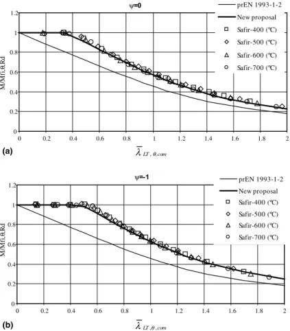
Numerical modelling of the lateral–torsional buck-ling of steel beams at elevated temperature has shown that the beam design curve from prEN 1993-1-2 (2003) [2] is over-conservative for bending moment diagrams other than uniform bending moment [5].
In accordance with the safety format of the lateral– torsional buckling code provisions for room tempera-ture design, an alternative proposal for rolled sections or equivalent welded sections subjected to fire was pre-sented by Vila Real et al. [5], that addressed the issue of the influence of the loading type on the resistance of the beam, leading to better agreement with the real behav-iour while maintaining safety.
The objective of the present paper is to evaluate the proposals made by Vila Real et al. [4] in terms of a consistent safety check for the stability of beam-col-umns subjected to lateral–torsional buckling under fire loading, but using the new proposal for lateral–tor-sional buckling of unrestrained beams in case of fire [5]. This new proposal will be also used with the design formulae for beam-columns from the prEN 1993-1-2 (2003).
More specifically, using the specialised finite element code SAFIR [6], results of second-order analysis, including imperfections, for a range of lengths, levels of axial force and loading cases, are compared with the
codified interaction formulae from part 1-2 of Eurocode 3 [2] (here denoted ‘‘prEN 1993-1-2’’ when the new proposal for lateral–torsional buckling [5] is not con-sidered and ‘‘prEN 1993-1-2/f’’ when this new proposal is included) and with the proposed adaptation [4] to fire loading of method 1 and method 2 in prEN 1993-1-1 (2003), henceforth denoted ‘‘EC3 Method 1, fi/f ’’ and ‘‘EC3 Method 2, fi/f’’ or ‘‘EC3 Method 1, fi’’ and ‘‘EC3 Method 2, fi’’, again if the new proposal for LTB [5] is considered or not. Finally, the safety of these proposals is discussed and established.
2. Numerical model
2.1. Basic hypotheses
This study is performed using the specialised finite element code SAFIR [6], which is a finite element code for geometrical and material non-linear analysis, spe-cially developed at the University of Liege for studying structures subjected to fire.
A three-dimensional (3D) beam element has been used, based on the following formulations and hypoth-eses:
Nomenclature
A area of the cross-section
E Young’s modulus
fy yield strength
kyy andkzy interaction factors that can be determined
according to the two methods
ky;h reduction factor for the yield strength at
temperatureha
kE;h reduction factor for the slope of the linear elastic range at temperatureha
MSAFIR resistant moment in the fire design situation given by SAFIR
My;fi;Ed design bending moment aboutyaxis for the fire design situation
My;fi;h;Rd design moment resistance about y axis of Class 1 or 2 cross-section at uniform tem-peratureha
Nfi;Ed design axial force for the fire design situa-tion
Nfi;h;Rd design axial force resistance at uniform temperatureha
Wel;y elastic section modulus for theyaxis Wpl;y plastic section modulus inyaxis Greeks
a imperfection factor
bM;LT equivalent uniform moment factor
corre-sponding to lateral–torsional buckling
bM;y equivalent uniform moment factor for they
axis
DMy;Ed moments due to the shift of the centroidal axis, which are equal to zero in case of classes 1, 2 and 3
cM0 partial safety factor (usuallycM0¼1:0) cM;fi partial safety factor for the fire situation
(usuallycM;fi¼1:0)
kLT non-dimensional slenderness for lateral–
torsional bucking at room temperature
kLT;h non-dimensional slenderness for lateral–
torsional buckling at temperatureha
vLT;fi reduction factor for lateral–torsional buck-ling in the fire design situation
vmin;fi minimum reduction factor of the y and z
axis for flexural buckling in the fire design situation
vy;fi reduction factor of the y axis for flexural
buckling in the fire design situation
vz;fi reduction factor of the z axis for flexural
• Displacement type element in a total co-rotational description.
• Prismatic element.
• The displacement of the node line is described by
the displacements of the three nodes of the element, two nodes at each end supporting seven degrees of freedom, three translations, three rotations and the warping amplitude, plus one node at the mid-length supporting one degree of freedom, namely the non-linear part of the longitudinal dis-placement.
Fig. 1. (a) Simply supported beam-column with non-uniform bending; (b) studied bending diagrams.
0.3 C
T C
C T
T 0.3
0.3
0.3
0.3
Fig. 2. Residual stresses: C––compression; T––tension.
ψ=0
0 0.2 0.4 0.6 0.8 1 1.2
0 0.2 0.4 0.6 0.8 1 1.2 1.4 1.6 1.8 2
M/
Mf
i,
θ
,R
d
M/
Mf
i,
θ
,R
d
prEN 1993-1-2
New proposal
Safir-400 (ºC)
Safir-500 (ºC)
Safir-600 (ºC)
Safir-700 (ºC)
com LT,θ,
λ
ψ=-1
0 0.2 0.4 0.6 0.8 1 1.2
0 0.2 0.4 0.6 0.8 1 1.2 1.4 1.6 1.8 2
prEN 1993-1-2
New proposal
Safir-400 (ºC)
Safir-500 (ºC)
Safir-600 (ºC)
Safir-700 (ºC)
com LT,θ,
λ
(a)
(b)
• The Bernoulli hypothesis is considered, i.e., in bend-ing, plane sections remain plane and perpendicular to the longitudinal axis and no shear deformation is considered.
• No local buckling is taken into account, which is the reason why only Class 1 and Class 2 sections can be used [1].
• The strains are small (von Karman hypothesis), i.e., 1
2 ou
ox1 ð1Þ
whereuis the longitudinal displacement andxis the longitudinal co-ordinate.
• The angles between the deformed longitudinal axis
and the undeformed but translated longitudinal axis are small, i.e.,
sinuffiu and cosuffi1
whereuis the angle between the arc and the chord of the translated beam finite element.
• The longitudinal integrations are numerically calcu-lated using Gauss’ method.
• The cross-section is discretised by means of triangu-lar or quadrilateral fibres. At every longitudinal point of integration, all variables, such as tem-perature, strain, stress, etc., are uniform in each fibre.
• The tangent stiffness matrix is evaluated at each iter-ation during the convergence process (pure Newton-Raphson method).
• Residual stresses are considered by means of initial and constant strains [7].
• The material behaviour in case of strain unloading is elastic, with the elastic modulus equal to the Young modulus at the origin of the stress–strain curve. In
Table 1
Correction factorskcfor the new proposal
Moment distribution Class 1, 2, 3 sections
kc
16w61 0:6þ0:3wþ0:15w
2butk c61
600º
0 0.2 0.4 0.6 0.8 1
0 0.2 0.4 0.6 0.8 1
Safir prEN 1993-1-2 prEN 1993-1-2 / f
600º
0 0.2 0.4 0.6 0.8 1
0 0.2 0.4 0.6 0.8 1
Safir prEN 1993-1-2 prEN 1993-1-2 / f
600º
0 0.2 0.4 0.6 0.8 1
0 0.2 0.4 0.6 0.8 1
Safir prEN 1993-1-2 prEN 1993-1-2 / f
600º
0 0.2 0.4 0.6 0.8 1
0 0.2 0.4 0.6 0.8 1
Safir prEN 1993-1-2 prEN 1993-1-2 / f
M/Mfi,θ,Rd
N/N
fi,
θ
,Rd
M/Mfi,θ,Rd
N/N
fi,
θ
,Rd
M/Mfi,θ,Rd
N/N
fi,
θ
,Rd
M/Mfi,θ,Rd
N/N
fi,
θ
,Rd
(a) (b)
(c) (d)
Fig. 4. Interaction diagrams of prEN 1993-1-2, forw¼0: (a)L¼2000 mm,kLT;fi¼0:62,ky;fi¼0:29,kz;fi¼1:06; (b)L¼2500 mm,
kLT;fi¼0:73,ky;fi¼0:36,kz;fi¼1:32; (c)L¼3000 mm,kLT;fi¼0:84,ky;fi¼0:43,kz;fi¼1:59; (d)L¼3500 mm,kLT;fi¼0:93,ky;fi¼0:50,
the same cross-section, some fibres that have yielded may therefore exhibit a decreased tangent modulus because they are still on the loading branch, whereas, at the same time, some other fibres behave elastically. The plastic strain is presumed not to be affected by a change in temperature [8].
• The elastic torsional stiffness at 20C, which is calcu-lated by the code, has been adapted in an iterative process in order to reflect the decrease of material stiffness at the critical temperature [9].
2.2. Case study
A simply supported beam-column with fork supports has been chosen to explore the validity of the beam safety conditions, as shown in Fig. 1a. With respect to the bending moment variation along the member length, two values, (1;0), of thewratio (see Fig. 1) have been investigated.
The casew¼1 was not studied here because this case is not affected by the new procedure for lateral–torsional
buckling [5], that is, when the w ratio equals 1, the
proposed formulae for the evaluation of the lateral– torsional buckling resistance of steel beams remains the
same as those proposed in the prEN 1993-1-2. The
parametric study of beam-columns for w¼1 has
al-ready been made by Vila Real et al. [4].
An IPE 220 steel section of grade S 235 has been used. Uniform temperature in the cross-section has been also used so that comparison between the numerical results and the eurocode could be made. In this paper
the temperature used was 600C, deemed to adequately
represent the majority of practical situations.
A lateral geometric imperfection given by the fol-lowing expression was considered:
yðxÞ ¼ l
1000sin px
l
ð2Þ
where l is the beam length. An initial rotation with a
maximum value of l=1000 rad at mid span was also
introduced.
The residual stresses adopted are constant across the thickness of the web and flanges. A triangular distribu-tion as shown in Fig. 2, with a maximum value of 0.3·235 MPa, for the S235 steel has been used [10].
The lengths of the studied elements, were chosen so that the adimensional slenderness were smaller than 2.
600º
0 0.2 0.4 0.6 0.8 1
0 0.2 0.4 0.6 0.8 1
Safir prEN 1993-1-2
prEN 1993-1-2 / f
600º
0 0.2 0.4 0.6 0.8 1
0 0.2 0.4 0.6 0.8 1
Safir prEN 1993-1-2 prEN 1993-1-2 / f
600º
0 0.2 0.4 0.6 0.8 1
0 0.2 0.4 0.6 0.8 1
Safir prEN 1993-1-2 prEN 1993-1-2 / f
600º
0 0.2 0.4 0.6 0.8
1
0 0.2 0.4 0.6 0.8 1
Safir prEN 1993-1-2 prEN 1993-1-2 / f
M/Mfi,θ,Rd
N/N
fi,
θ
,Rd
M/Mfi,θ,Rd
N/N
fi,
θ
,Rd
M/Mfi,θ,Rd
N/N
fi,
θ
,Rd
M/Mfi,θ,Rd
N/N
fi,
θ
,Rd
(a) (b)
(c) (d)
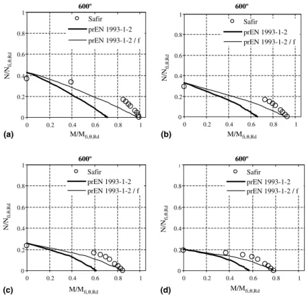
Fig. 5. Interaction diagrams of prEN 1993-1-2, forw¼ 1: (a)L¼2000 mm,kLT;fi¼0:51,ky;fi¼0:29,kz;fi¼1:06; (b)L¼2500 mm,
kLT;fi¼0:61,ky;fi¼0:36,kz;fi¼1:32; (c)L¼3000 mm,kLT;fi¼0:69,ky;fi¼0:43,kz;fi¼1:59; (d)L¼3500 mm,kLT;fi¼0:77,ky;fi¼0:50,
3. Improvement of the prEN 1993-1-2 proposal for lateral–torsional buckling
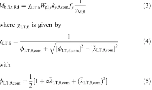
According to the proposal of prEN 1993-1-2 [2], the design lateral–torsional buckling resistance of a laterally unrestrained beam with Class 1 or 2 cross-section, is obtained as follows:
Mb;fi;t;Rd¼vLT;fiWpl;yky;h;comfy
1
cM;fi ð3Þ
wherevLT;fi is given by
vLT;fi¼
1
/LT;h;comþ
ffiffiffiffiffiffiffiffiffiffiffiffiffiffiffiffiffiffiffiffiffiffiffiffiffiffiffiffiffiffiffiffiffiffiffiffiffiffiffiffiffiffiffiffiffiffiffi
½/LT;h;com2 ½kLT;h;com 2
q ð4Þ
with
/LT;h;com¼1
2½1þakLT;h;comþ ðkLT;h;comÞ 2
ð5Þ
whereky;h;comis the reduction factor for the yield strength at the maximum temperature in the compression flange ha;comreached at timet;cM;fi is the partial safety factor for the fire situation (usuallycM;fi¼1).
The non-dimensional slendernesskLT;h;com(orkLT;fi, if
the temperature field in the cross-section is uniform) is given by
kLT;h;com¼kLT;fi¼kLT
ffiffiffiffiffiffiffiffiffiffiffiffiffiffi
ky;h;com
kE;h;com
s
ð6Þ
wherekE;h;comis the reduction factor for the slope of the linear elastic range at the maximum steel temperature reached at timet.
In this proposal, the imperfection factorais a func-tion of the steel grade and is given by:
a¼0:65 ffiffiffiffiffiffiffiffiffiffiffiffiffiffi235=fy
q
ð7Þ
As shown in Fig. 3, for the two values of thewratio,)1
and 0, these formulae (from prEN 1993-1-2) lead to over-conservative results when compared to numerical results for the case of non-uniform bending. To avoid these over-conservative results, Vila Real et al. [5] have made a new proposal that adopts a modified reduction factor for lateral–torsional buckling,vLT;fi;mod, given by
600º
0 0.2 0.4 0.6 0.8 1
0 0.2 0.4 0.6 0.8 1
Safir
EC3 Method 1, fi EC3 Method 1, fi / f EC3 Method 2, fi EC3 Method 2, fi / f
600º
0 0.2 0.4 0.6 0.8
1
0 0.2 0.4 0.6 0.8 1
Safir
EC3 Method 1, fi EC3 Method 1, fi / f EC3 Method 2, fi EC3 Method 2, fi / f
600º
0 0.2 0.4 0.6 0.8 1
0 0.2 0.4 0.6 0.8 1
Safir
EC3 Method 1, fi EC3 Method 1, fi / f EC3 Method 2, fi EC3 Method 2, fi / f
600º
0 0.2 0.4 0.6 0.8 1
0 0.2 0.4 0.6 0.8 1
Safir
EC3 Method 1, fi EC3 Method 1, fi / f EC3 Method 2, fi EC3 Method 2, fi / f
M/Mfi,θ,Rd
N/N
fi,
θ
,Rd
M/Mfi,θ,Rd
N/N
fi,
θ
,Rd
M/Mfi,θ,Rd
N/N
fi,
θ
,Rd
M/Mfi,θ,Rd
N/N
fi,
θ
,Rd
(a) (b)
(c) (d)
Fig. 6. Interaction diagrams of prEN 1993-1-1 at 600 C for w¼0: (a)L¼2000 mm,kLT;fi¼0:62, ky;fi¼0:29, kz;fi¼1:06; (b)
L¼2500 mm, kLT;fi¼0:73, ky;fi¼0:36, kz;fi¼1:32; (c) L¼3000 mm, kLT;fi¼0:84, ky;fi¼0:43, kz;fi¼1:59; (d) L¼3500 mm,
vLT;fi;mod¼ vLT;fi
f butvLT;fi;mod61 ð8Þ
wherefdepends on the loading type and is given by the following equation
f¼10:5ð1kcÞ ð9Þ
wherekcis a correction factor according to Table 1. As it can be seen in Fig. 3, this new proposal shows a very good agreement with the numerical results.
4. Interaction formulae for beam-columns at high tem-peratures
4.1. Interaction formulae proposed by prEN 1993-1-2
For fire loading, according to the new version of part 1-2 of Eurocode 3 [2], the interaction equations for beam-columns are:
Nfi;Ed
vz;fiAky;h
fy cM;fi
þ KLTMy;fi;Ed vLT;fiWpl;yky;h
fy cM;fi
61 ð10Þ
where
KLT¼1
lLTNfi;Ed vz;fiAky;h
fy cM;fi
butKLT61:0 ð11Þ
and
lLT¼0:15kz;hbM;LT0:15 butl60:9 ð12Þ
Here vfi are the reduction factors for flexural buckling around the yy and zz axis, and vLT;fi is the reduction factor for lateral–torsional buckling, given by (4).
These formulae for the design of beam-columns are based on the ENV 1993-1-1 (1992) [3].
To study the described methods, for each selected
beam-column length and bending moment ratio
wð0;1Þ, illustrated in Fig. 3, the interaction equation (10) was plotted for increasing ratios of N=Nfi;h;Rd,
to-gether with the results of the numerical simulations for a uniform temperature of 600C, as shown in Figs. 4 and 5. In these figures, the results from equation (10) are denoted by ‘‘prEN 1993-1-2’’ whenever the new pro-posal for LTB is not considered and ‘‘prEN 1993-1-2/f’’ otherwise.
From Figs. 4 and 5 it is concluded that the new proposal for LTB introduces a significant improvement
600º
0 0.2 0.4 0.6 0.8 1
0 0.2 0.4 0.6 0.8 1
Safir
EC3 Method 1, fi EC3 Method 1, fi / f EC3 Method 2, fi EC3 Method 2, fi / f
600º
0 0.2 0.4 0.6 0.8 1
0 0.2 0.4 0.6 0.8 1
Safir
EC3 Method 1, fi EC3 Method 1, fi / f EC3 Method 2, fi EC3 Method 2, fi / f
600º
0 0.2 0.4 0.6 0.8 1
0 0.2 0.4 0.6 0.8 1
Safir
EC3 Method 1, fi EC3 Method 1, fi / f EC3 Method 2, fi EC3 Method 2, fi / f
600º
0 0.2 0.4 0.6 0.8 1
0 0.2 0.4 0.6 0.8 1
Safir
EC3 Method 1, fi EC3 Method 1, fi / f EC3 Method 2, fi EC3 Method 2, fi / f
M/Mfi,θ,Rd
N/N
fi,
θ
,Rd
(a) M/Mfi,θ,Rd
N/N
fi,
θ
,Rd
(b)
N/N
fi,
θ
,Rd
(c) M/Mfi,θ,Rd M/Mfi,θ,Rd
N/N
fi,
θ
,Rd
(d)
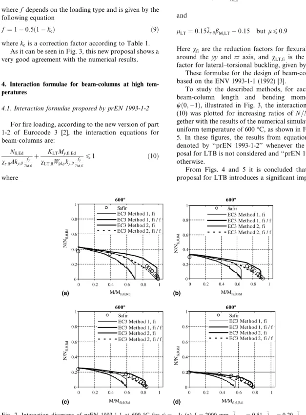
Fig. 7. Interaction diagrams of prEN 1993-1-1 at 600C forw¼ 1: (a)L¼2000 mm,kLT;fi¼0:51,ky;fi¼0:29,kz;fi¼1:06; (b)
L¼2500 mm, kLT;fi¼0:61, ky;fi¼0:36, kz;fi¼1:32; (c) L¼3000 mm, kLT;fi¼0:69, ky;fi¼0:43, kz;fi¼1:59; (d) L¼3500 mm,
in the interaction diagrams, for beam-columns with lateral–torsional buckling.
4.2. Proposed interaction formulae based on prEN 1993-1-1 proposal
Vila Real et al. [4] have proposed the follow-ing interaction formulae for beam-columns in case of fire:
Nfi;Ed
vy;fi
Nfi;Rk
cM;fi
þkyy;fi
My;fi;EdþDMy;fi;Ed
vLT;fi
My;fi;Rk
cM;fi
61 ð13aÞ
Nfi;Ed
vz;fi
Nfi;Rk
cM;fi
þkzy;fi
My;fi;EdþDMy;fi;Ed
vLT;fi
My;fi;Rk
cM;fi
61 ð13bÞ
wherevfiare the reduction factors for flexural buckling around the yy and zz axes, and vLT;fi is the reduction factor for lateral–torsional buckling, calculated accord-ing to (4).
These interaction formulae are based on the prEN 1993-1-1 provided that some factors are changed to take into consideration high temperatures. The factors
changed were the yield stress, the Young modulus, and the reduction factorsvfifor flexural buckling around the
yy andzzaxes, andvLT;fi for lateral–torsional buckling according to the proposals of prEN 1993-1-2.
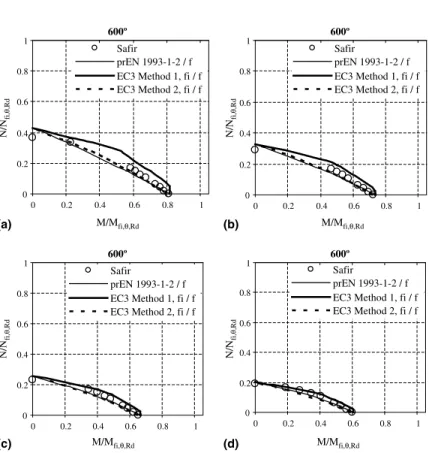
The factorskyy;fiandkzy;fiare the interaction factors in case of fire that can be determined by two alternative methods (‘‘EC3 Method 1, fi’’ and ‘‘EC3 Method 2, fi’’) described in Vila Real et al. [4]. Also, if the new proposal of Vila Real et al. [5] for lateral–torsional buckling is used, two additional methods are obtained (‘‘EC3 Method 1, fi/f’’ and ‘‘EC3 Method 2, fi/f’’) all illustrated in Figs. 6–9.
The procedure for the evaluation of the interaction factors for ‘‘EC3 Method 1, fi’’ is based on method 1 at room temperature, that is reported in Annex A of part 1.1 of EC3 [1] and was developed by a French-Belgian team [11] combining theoretical rules and numerical calibration to account for all the differences between the real model and the theoretical one. The specific formulae for the calculation of the interaction factors according to method 1 in case of fire are:
kyy;fi¼cmy;ficmLT;fi
ly;h 1Nfi;Ed
Ncr;y;fi
c1
yy;fi ð
14Þ
600º
0 0.2 0.4 0.6 0.8 1
0 0.2 0.4 0.6 0.8 1
Safir
prEN 1993-1-2 / f EC3 Method 1, fi / f EC3 Method 2, fi / f
600º
0 0.2 0.4 0.6 0.8 1
0 0.2 0.4 0.6 0.8 1
Safir
prEN 1993-1-2 / f EC3 Method 1, fi / f EC3 Method 2, fi / f
600º
0 0.2 0.4 0.6 0.8 1
0 0.2 0.4 0.6 0.8 1
Safir
prEN 1993-1-2 / f EC3 Method 1, fi / f EC3 Method 2, fi / f
600º
0 0.2 0.4 0.6 0.8 1
0 0.2 0.4 0.6 0.8 1
Safir
prEN 1993-1-2 / f EC3 Method 1, fi / f EC3 Method 2, fi / f
M/Mfi,θ,Rd
N/N
fi,
θ
,Rd
(a) M/Mfi,θ,Rd
N/N
fi,
θ
,Rd
(b)
M/Mfi,θ,Rd
N/N
fi,
θ
,Rd
(c) M/Mfi,θ,Rd
N/N
fi,
θ
,Rd
(d)
Fig. 8. Interaction diagrams considering the new proposal for lateral–torsional buckling, forw¼0: (a)L¼2000 mm,kLT;fi¼0:62,
ky;fi¼0:29, kz;fi¼1:06; (b) L¼2500 mm, kLT;fi¼0:73, ky;fi¼0:36, kz;fi¼1:32; (c) L¼3000 mm, kLT;fi¼0:84, ky;fi¼0:43,
kzy;fi¼cmy;ficmLT;fi lz;h 1Nfi;Ed
Ncr;y;fi
1
czy;fi
0:6 ffiffiffiffiffi
wy
wz
r
ð15Þ
cmy;fi¼cmy;fi;0þ ð1cmy;fi;0Þ
ffiffiffiffiffiffiffi
ey;fi
p a
LT 1þ ffiffiffiffiffiffiffie
y;fi
p a
LT ð
16Þ
cmLT;fi¼c2my;fi
aLT
ffiffiffiffiffiffiffiffiffiffiffiffiffiffiffiffiffiffiffiffiffiffiffiffiffiffiffiffiffiffiffiffiffiffiffiffiffiffiffiffiffiffiffiffiffiffiffi 1Nfi;Ed
Ncr;z;fi
1Nfi;Ed
Ncr;T;fi
r ð17Þ
ey;fi¼
My;fi;Ed
Nfi;Ed
A
Wel;y ð
18Þ
Due to the non-linearity introduced by the factorey
the interaction curves were obtained using an iterative procedure. It was assumed that the moment of each studied beam-column could not exceed its design buckling resistance moment, Mb;Rd;fi. This justifies
the vertical branch of some interaction curves of method 1.
‘‘EC3 Method 2, fi’’ is related to method 2 at room temperature, which is described in Annex B of part 1.1 of EC3 [1] and results from an Austrian-German pro-posal [12] that attempted to simplify the verification of
the stability of beam-columns, all interaction factors being obtained by means of numerical calibration. These factors are not clearly understandable from a physical point of view, but this simple formulation simplifies the verification procedure and reduces the possibility of mistakes.
The interaction factors according to method 2 in case of fire should be calculated from:
kyy;fi¼cmy;fi 1
0
@ þ ðky;h0:2Þ
Nfi;Ed
vy;fi
Nfi;Rk
cM;fi
1
A
6cmy;fi 1 0
@ þ0:8
Nfi;Ed
vy;fiNfi;Rk
cM;fi
1
A ð19Þ
kzy¼1
0:1kz;h
cmLT0:25
Nfi;Ed
vz;fi
Nfi;Rk
cM;fi
P1 0:1
cmLT0:25
Nfi;Ed
vz;fi
Nfi;Rk
cM;fi
forkz;h<0:4
kzy¼0:6þkz;h61
0:1kz;h
cmLT0:25
Nfi;Ed
vz;fi
Nfi;Rk
cM;fi
ð20Þ 600º 0 0.2 0.4 0.6 0.8 1
0 0.2 0.4 0.6 0.8 1
Safir
prEN 1993-1-2 / f EC3 Method 1, fi / f EC3 Method 2, fi / f
600º 0 0.2 0.4 0.6 0.8 1
0 0.2 0.4 0.6 0.8 1
Safir
prEN 1993-1-2 / f EC3 Method 1, fi / f EC3 Method 2, fi / f
600º 0 0.2 0.4 0.6 0.8 1
0 0.2 0.4 0.6 0.8 1
Safir
prEN 1993-1-2 / f EC3 Method 1, fi / f EC3 Method 2, fi / f
600º 0 0.2 0.4 0.6 0.8 1
0 0.2 0.4 0.6 0.8 1
Safir
prEN 1993-1-2 / f EC3 Method 1, fi / f EC3 Method 2, fi / f
M/Mfi,θ,Rd
N/N
fi,
θ
,Rd
(a)
M/Mfi,θ,Rd
N/N
fi,
θ
,Rd
(c)
M/Mfi,θ,Rd
N/N
fi,
θ
,Rd
(b)
M/Mfi,θ,Rd
N/N
fi,
θ
,Rd
(d)
Fig. 9. Interaction diagrams considering the new proposal for lateral–torsional buckling, forw¼ 1: (a)L¼2000 mm,kLT;fi¼0:51,
ky;fi¼0:29, kz;fi¼1:06; (b) L¼2500 mm, kLT;fi¼0:61, ky;fi¼0:36, kz;fi¼1:32; (c) L¼3000 mm, kLT;fi¼0:69, ky;fi¼0:43,
where
cmi;fi¼0:6þ0:4wiP0:4 ð21Þ
Figs. 6 and 7 show the influence of considering or not the new proposal for LTB [5] with method 1 and method
2 adapted to elevated temperatures, for w¼0 and
w¼ 1 respectively. It can be observed in those figures that the new proposal for LTB introduces a great improvement in the interaction diagrams for both methods.
Finally in Figs. 8 and 9, all the three methods studied here, considering the new proposal for the lateral–tor-sional buckling of beams [5] are plotted together, show-ing a very good agreement with the numerical results.
5. Conclusions
It has been shown that the proposed methods for the lateral–torsional buckling of unrestrained steel beams at high temperatures, introduce significant improvements in the design curves of beam-columns under fire conditions. If method 1 and method 2 are adopted, there is the advantage of using the same formulae at room temper-ature and at elevated tempertemper-ature, being in line with the procedure always adopted in the Eurocodes. The results have shown that the method 1 sometimes is not in the safe side. These aspects should be considered when the new proposal for the resistance of beam-columns has to be chosen in the next revision of the Eurocode 3.
Although the study presented in this paper recom-mends the use of one of these proposals in future ver-sions of part 1-2 of the Eurocode 3, more numerical and experimental tests are needed, so that the validity of these proposals can be thoroughly assessed, namely the use of different steel grades and cross-sectional shapes.
References
[1] Eurocode 3, Design of Steel Structures––part 1-1. General rules and rules for buildings. prEN 1993-1-1:2003, Stage 49
Draft, European Committee for Standardisation, Brussels, Belgium, May 2003.
[2] Eurocode 3, Design of Steel Structures––part 1-2. General rules––Structural fire design. Draft prEN 1993-1-2:2003, Stage 49 Draft, European Committee for Standardisation, Brussels, Belgium, April 2003.
[3] Eurocode 3, Design of Steel Structures––part 1-1. General rules and rules for buildings. ENV 1993-1-1, Commission of the European Communities, Brussels, Belgium, 1992.
[4] Vila Real PMM, Lopes N, Sim~oes da Silva L, Piloto P,
Franssen J-M. Towards a consistent safety format of steel beam-columns: application of the new interaction formulae for ambient temperature to elevated temperatures. Steel Compos Struct 2003;3(6):383–401.
[5] Vila Real PMM, Lopes N, Sim~oes da Silva L, Franssen
J-M. Lateral–torsional buckling of unrestrained steel beams under fire conditions: improvement of EC3 pro-posal. Comput Struct, in press.
[6] Franssen J-M. SAFIR. A thermal/structural program modeling structures under fire. In: Proc NASCC Confer-ence, American Inst for Steel Constr, Baltimore, April 2003.
[7] Franssen J-M. Modelling of the residual stresses influence in the behaviour of hot-rolled profiles under fire conditions
in French Construct Metall 1989;3:35–42.
[8] Franssen JM. The unloading of building materials sub-mitted to fire. Fire Safety J 1990;16:213–27.
[9] Souza V, Franssen J-M. Lateral buckling of steel I beams at elevated temperature––comparison between the
model-ling with beam and shell elements. In: Lamas A, Simoes da~
Silva L, editors. Proc 3rd European Conf on Steel Structures, Coimbra: Univ. de Coimbra; 2002. p. 1479– 88. ISBN: 972-98376-3-5.
[10] ECCS––European Convention for Constructional Steel-work, Technical Committee 8––Structural Stability, Tech-nical Working Group 8.2––System, ‘‘Ultimate Limit State Calculation of Sway Frames With Rigid Joints’’, 1st ed., 1984.
[11] Boissonnade N, Jaspart J-P, Muzeau J-P, Villette M. New interaction formulae for beam-columns in Eurocode 3: the
French-Belgian approach. J Construct Steel Res
2004;60(3–5):421–31.