BJRS
RADIATION SCIENCES
07-02A (2019) 01-18ISSN: 2319-0612
Accept Submission: 2018-08-13
Proposal for a radiation shielding study aiming the
implan-tation of neutrons beam shutter in the j-9 radiation channel
of the argonauta reactor of the nuclear engineering institute.
L. R. P. Xavier
1; D. O. Cardoso
1; F. J. O. Ferreira
2; D. L. Voi
21 Instituto Militar de Engenharia (IME), 22291-270, Rio de Janeiro, RJ, Brazil
larissa.xavier@cnen.gov.br domingosoliveiralvr71@gmail.com
2 Instituto de Engenharia Nuclear (IEN), 21941-614, Ilha do Fundão, RJ, Brazil
fferreira@ien.gov.br dante@ien.gov.br
ABSTRACT
Argonauta, the only nuclear research reactor situated in Rio de Janeiro, located at the Institute of Nuclear Engineering (IEN), regularly serves a network of users focused on research and development, and also provides its infrastructure for experimental classes and completion work course. Due to increasing demand for non-destructive thermal neutron assays and production of radioisotopes, there is a search for new procedures and/or devices that optimize users' exposure to neutrons. The implementation of mechanisms that allow access to the irradiation channels without the reactor being turned off and with a shielding configuration that limits the occupational doses at this location is very useful for the operation of the reactor. In order to achieve this, the present work proposes the establishment of a neutron beam shutter of the J-9 irradiation channel of the IEN’s Argonauta reactor. In a first step, experimental measurements were made in the irradiation channel of the reactor using a BF3 detector, which is coupled to a spectrometer. In this phase, the neutron
beam was aligned to the spectrometer, and different materials were used as shields, aiming the attenuation of the beam. To validate and/or change the configuration of the barrier that best meets the material irradiation needs, a second planned phase is involving the neutron flux simulation of the reactor and the various shields with different boundary
conditions using the particle transport code, Monte Carlo N-Particle Extended (MCNP- X).
Keywords: Radioprotection, Radiological shielding, Argonauta reactor, Neutron beam, Neutron beam shutter.
1. INTRODUCTION
Radiological Protection is the set of measures that aims to protect man, his descendants and the en-vironment from possible harmful effects of ionizing radiation, thus allowing the activities that make use of this type of radiation [2,4].
The basic principle of radiological protection known as ALARA (As Low As Reasonably Achieva-ble) states that all exposures should be kept as low as reasonably achievable. This is because low-dose radiobiological studies have shown that there is no real low-dose threshold for stochastic effects. Thus, the exposure of any tissue involves a carcinogenic risk, depending on the radiosensitivity of that tissue. Therefore, the application of this principle requires the optimization of radiation protec-tion in all situaprotec-tions where they can be controlled by protective measures, particularly in the selec-tion, planning of equipment, operations and protection systems [9, 13, 15].
One of the activities of radiological protection, which corroborates this principle, is the specifica-tion and design of materials that can be used as protecspecifica-tion barriers, in order to minimize the effects of doses of ionizing radiation on workers and individuals in the public.
The installation of a beam shutter in the J-9 irradiation channel will be an important factor for radio-logical safety, minimizing the chronic exposure of occupationally exposed individuals and other users of the reactor. Also from an operational point of view, it will allow access to the experimental arrangements without the reactor being shut down, as is the case today. Thus, there will be the im-provement and expansion of the research activities with the reactor, as it will make possible the implementation of new experimental techniques, as well as optimize the attendance of the increas-ing demand related to the renderincreas-ing of services usincreas-ing the reactor. This study will contribute not only to the attendance of the current neutron flux, but also to the possibility of increasing this flow, in order to be made available in the future demand of the activities of the Argonauta.
2. MATERIALS AND METHODS
The reactor in question is a low-power thermal reactor, designed to achieve up to 5 kW of power, although its usual operation is at 340 W.
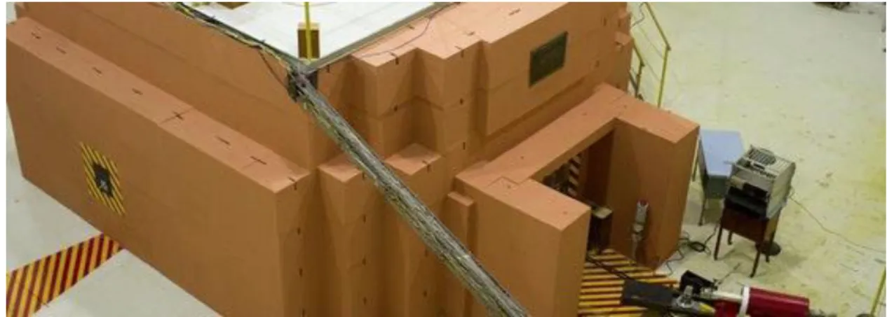
Figure 1: Argonauta reactor located at the Nuclear Engineering Institute
The core of the Argonauta consists of two concentric aluminum cylinders forming a ring where the fuel elements formed by plates are placed and separated by graphite wedges. Between the plates circulates water for refrigeration and moderation of the neutrons. The current fuel configuration in the core is eight symmetrically distributed fuel elements, each consisting of seventeen uranium ox-ide (U3O8) fuel plates fixed by two aluminum pins.
The outer thermal column is located on the front of the reactor, and contains thirteen removable graphite blocks for conducting experiments. The main channel, which is used in this work, called J-9, has the largest neutron flux since it reaches the outer aluminum tank at half height of the fuel elements. The depth of the other channels reaches only the external reflector. At the exit of the J-9 channel is installed the crystal spectrometer, where is the BF3 detector used in the experiments [10,
11,14].
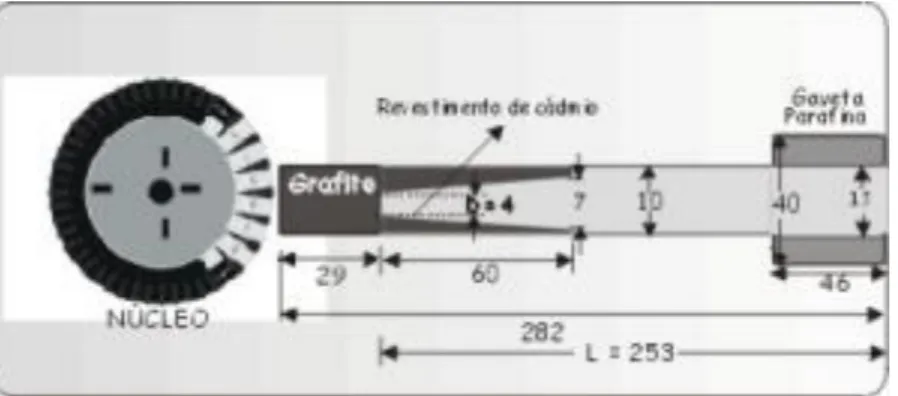
A collimator-moderator arrangement is used within the J-9 channel providing the neutron character-istics, which are presented below [3].
Figure 2: Collimator-moderator arrangement on the J-9
Source: IEN website
Table 1: Characteristics of the neutron flux. Reactor power: 170 W
Thermal flux 2.23 106 n.cm-2s-1
Epithermal flux 3.18 103 n.cm-2s-1
Neutron/gamma ratio 3.00 106 n.cm-2mR-1
L/D collimation rate 63.25
To perform the neutron detection at the output of the J-9 were used an experimental array composed of: pre-amplifier, multichannel analyzer, which includes the 2000 V power supply, amplifier, and multichannel buffer, and associated electronic [1,6,7,8,10,19].
In the first stage of the work the alignment of the neutron beam of the J-9 channel with the BF3
de-tector was regulated, in order to obtain the best position, that is, where the largest neutron flux was found.
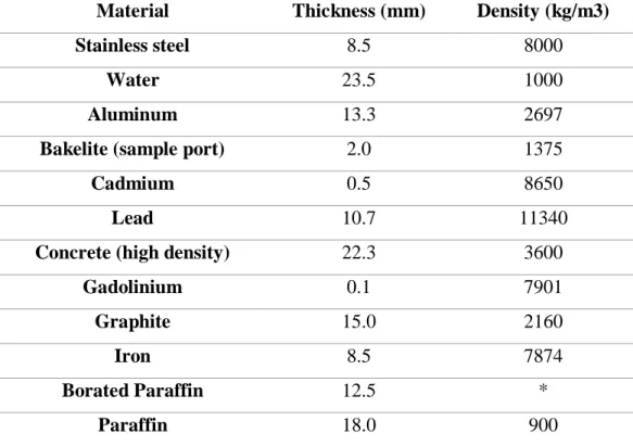
After this stage, different types of materials were selected by SEREA – Reactor Service – from In-stitute of Nuclear Engineering, in order to attenuate the neutron beam, and to provide a better radio-protection for the operators and users, by choosing the shield that meets simultaneously the above quoted items positioned at the exit of J-9 channel. The materials used and their characteristics may be observer below [5].
Table 2: Characteristics of the materials that served as shielding to the beam of J-9 radiation
channel.
Material Thickness (mm) Density (kg/m3)
Stainless steel 8.5 8000
Water 23.5 1000
Aluminum 13.3 2697
Bakelite (sample port) 2.0 1375
Cadmium 0.5 8650
Lead 10.7 11340
Concrete (high density) 22.3 3600
Gadolinium 0.1 7901 Graphite 15.0 2160 Iron 8.5 7874 Borated Paraffin 12.5 * Paraffin 18.0 900 * In determination
3. RESULTS AND DISCUSSION
Following the methodology, it was initiated by the alignment of the emerging beam of the J-9 chan-nel with the spectrometer, where the BF3 detector is located. The best position for the spectrometer
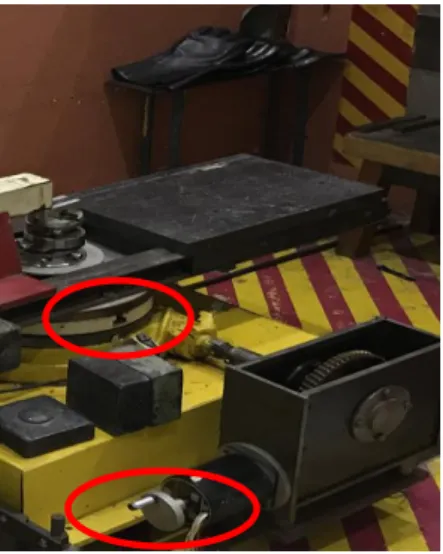
would be the point where the largest direct beam was measured, as it would be possible to work with the largest neutron beam, and consequently, a better counting statistic. To obtain the proper positioning, the spectrometer was mounted on a railing system that allows the rotation of this equipment up to 360 degrees, with minimum variations of 1 degree.
Figure 3: Rotatory adjustment with the function of aligning the spectrometer to the
irradia-tion beam of J-9 channel
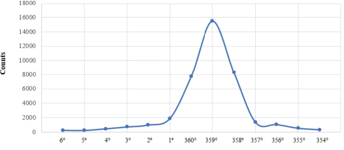
For the first experiment, measurements were made between the positions of 354 to 0 and 0 to 6 de-grees, with an interval of 1 degree. For each grade three measurements were made (each of 30 sec-onds), and the average was found. It was observed that the highest neutron flux was obtained at the 359 degree position, as shown in the Figure 4. In this condition, the relation between the peak width assigned to neutron detection and the peak width obtained with gamma detection was also checked. The width found for the neutron was 682 channels, and for gamma the 24 channels, thus the ratio of 28.4 was obtained. The work was carried out with the power of the reactor in 34 Watts.
Figure 4: Number of neutron counts per degree, in the direct flow
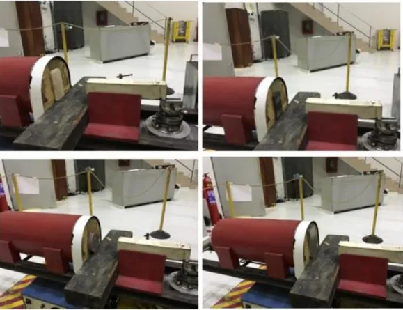
At this stage, keeping the spectrometer aligned at position 359, the second phase of the work was started. The power of the reactor was increased to 170 Watts and the relation between the neutron peak width and the gamma width was the 686 channels for 24 channels, obtaining a value of 28.6, thus maintaining the above-mentioned relation even with the increase in power, confirming that the detector saturation did not occur. In the same way, three measures (each 300 seconds) were made for the direct (unshielded) beam, and then measurements were taken for different types of materials, which could be used as shielding. In the following figure, it is possible to observe the structure mounted with some of the barriers.
Figure 5: Structure assembled for the experiment, with some of the shields (borated
paraf-fin, lead, concrete and aluminum)
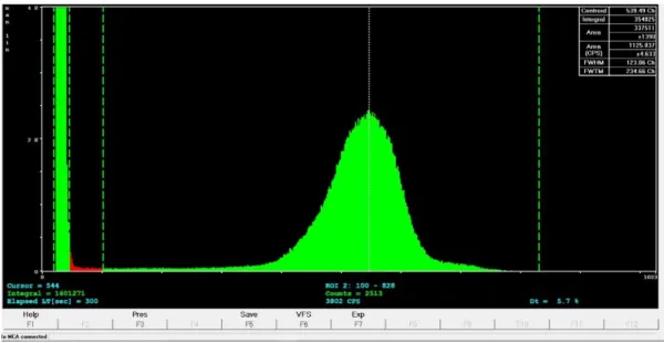
Starting with the direct beam the average of the counts found for the neutron fluxes was 348014, with a standard deviation of 6%. One of the spectra obtained in the multichannel buffer is followed.
Figure 6: Spectrum of the direct irradiation beam of the J-9 channel
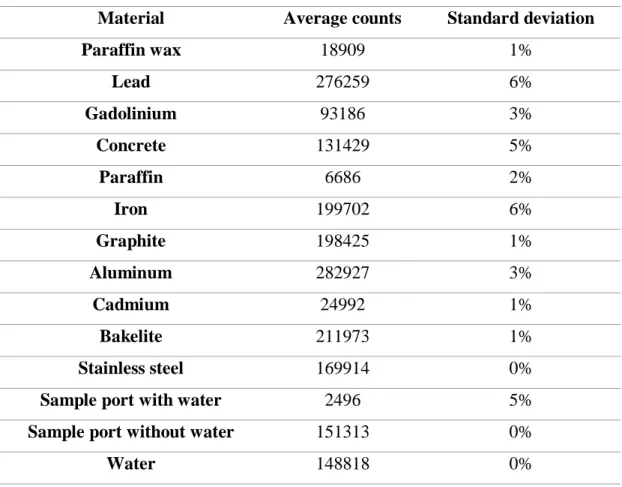
The same procedure used for the direct beam was made for each of the materials separately. Below are the average counts and the standard deviation for the various shields.
Table 3: Average counts and standard deviation for the different materials
Material Average counts Standard deviation
Paraffin wax 18909 1% Lead 276259 6% Gadolinium 93186 3% Concrete 131429 5% Paraffin 6686 2% Iron 199702 6% Graphite 198425 1% Aluminum 282927 3% Cadmium 24992 1% Bakelite 211973 1% Stainless steel 169914 0%
Sample port with water 2496 5%
Sample port without water 151313 0%
Water 148818 0%
The neutron count for water was found by decreasing the value found for the sample port without water and that found for the sample port with water.
For a better presentation of the obtained results, the spectrum obtained with the direct beam and with the studied block material will be arranged together, thus allowing the choice of the best exper-imental arrangement of neutron shielding for the output of the J-9 channel.
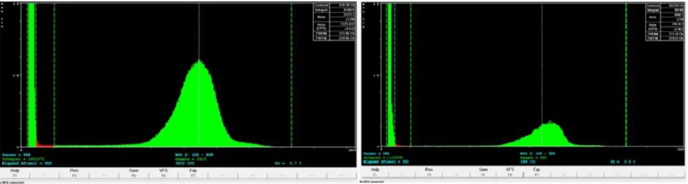
Figure 7: Direct beam x Attenuated beam by Borated Paraffin
Figure 8: Direct beam x Attenuated beam by Lead
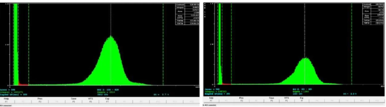
Figure 10: Direct beam x Attenuated beam by Concrete
Figure 11: Direct beam x Attenuated beam by Paraffin
Figure 13: Direct beam x Attenuated beam by Graphite
Figure 14: Direct beam x Attenuated beam by Aluminum
Figure 16: Direct beam x Attenuated beam by Bakelite
Figure 17: Direct beam x Attenuated beam by Stainless steel
Figure 19: Direct beam x Attenuated beam by Sample pot without water
The counts and spectra obtained due to the different attenuations were observed, the best materials to be used for the shielding of the neutron flux under study were found. Below is presented the at-tenuation capacity achieved by each material and consequently its possible utility for the construc-tion and implementaconstruc-tion of an obturator for the neutron beam from the J-9 irradiaconstruc-tion channel of the Argonauta reactor.
Table 4: Percentage of attenuation of the different materials
Material Percentage of attenuation
Paraffin 98,1% Bored paraffin 94,6% Cadmium 92,8% Gadolinium 73,2% Concrete 62,2% Water 57,2% Stainless steel 51,2% Graphite 43,0% Iron 42,6% Bakelite 39,1% Lead 20,6% Aluminum 18,7%
The attenuation for the sample port with water and no water were only used to find the value of the attenuation for the water, so these materials were not included in the table above.
4. CONCLUSION
With the experimental data obtained in this work the best materials to be used as shielding for the neutron flux of the output of the J-9 channel were found. They are: paraffin, borated paraffin and cadmium. This work continues with the development of the reactor neutron flux simulation stage and the various shields with different conditions using the transport code, Monte Carlo N-Particle Extended (MCNP-X) [12,16,17,18]. After obtaining the simulation results, they will be compared with the experimental results presented here, in order to point out the best material composition, thicknesses and/or arrangements to be used in the implementation of a neutron beam shutter of the J-9 irradiation channel of the IEN’s Argonauta reactor.
5. ACKNOWLEDGMENT
This work would not be possible without the knowledge and teachings of my dear advisers Domin-gos, Francisco and Dante, and the technical support of the entire Argonauta reactor team, especially Rogerio Chaffin, João Carlos Santos Pereira, André Luis Nunes Barbosa, João Alberto Gadelha and Flavio Guimarães Porto. Thanks also to Lilia Crissiuma Palhares who supported me and made it possible. To the Institute of Military Engineering (IME), to the Institute of Nuclear Engineering (IEN) and the National Commission of Nuclear Energy (CNEN).
REFERENCES
1. A.X. Silva, “Uso de um feixe de nêutrons térmicos para detecção de narcóticos e explosivos por tomografia para aplicação na Segurança Pública Nacional, Tese de Doutorado, COPPE/UFRJ, Rio de Janeiro, 1999.
2. B. P. Mazzili, R.F. Christovam, Y. Kodama, F. F. Suzuki, J. C. Dellamano, J. T. Marumo, M. P. Sanches, R. Vicente, S. A Bellintani, “Noções básicas de proteção radiológica”, IPEN, São Pau-lo, 2002.
3. C.A.C. Renke, “Estudo da Moderação de Nêutrons na Direção do Canal J-9 do Reator Argonau-ta”, Nota Técnica, IEN/CNEN, Rio de Janeiro, 1993.
4. Comissão Nacional de Energia Nuclear, “CNEN- NN-3.01, Diretrizes de proteção radiológica”, 2014.
5. D.L. Voi, “Estudo da Estabilidade e Dinâmica Moleculares da Baquelite através de medidas de seção de choque para nêutrons”, Tese de Doutorado, COPPE/UFRJ, Rio de Janeiro, 1990. 6. D. Reilly, N. Ensslin, H. Smith, “Passive nondestructive assay of nuclear materials”, NRC,
Washington, 1991.
7. D. Reilly, N. Ensslin, H. Smith, “Passive nondestructive assay of nuclear materials”, Springfield - NTIS, Volume 1, pp.1-335, 1991.
8. D. Reilly, N. Ensslin, H. Smith, “Passive nondestructive assay of nuclear materials”, Springfield - NTIS, Volume 2, pp.1-337-700, 1991.
9. F.H. Attix, “Introduction to radiological physics and radiation dosimetry”, John Wiley and Sons, pp.1-607, 1986.
10. F.J.O. Ferreira, “Estudo para implantação de um sistema eletrônico para aquisição de imagens neutrongráficas no Reator Argonauta do IEN/CNEN”, Tese de Mestrado, COPPE/UFRJ, Rio de Janeiro, 2003.
11. H.A. Mello, E. Intrator, “O Reator Argonauta”, IEN, Rio de Janeiro, 1965.
12. J.D.A. Medeiros, “Introdução ao Método de Monte Carlo”, Tese de Graduação, UFPE, Pernam-buco, 1980.
13. J.J. Duderstadt, L.J. Hamilton, “Nuclear Reactor Analysis”, John Wiley and Sons, pp.1-650, 1976.
14. L.O.B Aghina, “Relatório de análise de Segurança do reator Argonauta”, IEN, Rio de Janeiro, 1989.
15. L. Tauhata, I.P.A. Salati, R. Di Prinzio, M.A.R.R. Di Prinzio, “Radioproteção e Dosimetria: Fundamentos”, IRD/CNEN, Rio de Janeiro, 2014.
16. R. Ramos, “Modelagem de um sistema neutrongráfico baseado em uma fonte de 241Am-Be, utilizando o Método de Monte Carlo, Tese de Mestrado, COPPE/UFRJ, Rio de Janeiro, 2004. 17. R.P.M. Ferreira, “O método de Monte Carlo e a simulação de sistemas multiagentes”,
Aba-kós/PUC Minas, Belo Horizonte, 2012.
18. V.L.L. Cunha, “Simulação do reator Argonauta/IEN utilizando o código MNCPX, Tese de Mes-trado, IME, Rio de Janeiro, 2010.
19. V.R. Crispim, J.J.G Silva, “Inspeções Não-Destrutivas com Neutrongrafia Térmica”, Revista de Física Aplicada e Instrumentação, Rio de Janeiro, Volume 11, n. 1, 1996.