A dynamic event
processing framework
for high performance
streams
Sérgio Miguel Mendes de Faria
Mestrado Integrado em Engenharia de Redes e Sistemas Informáticos
Departamento de Ciências de Computadores 2014
Orientador
Prof. Doutor Miguel Tavares Coimbra, Professor Auxiliar, DCC-FCUP
Coorientador
Todas as correções determinadas pelo júri, e só essas, foram
efetuadas.
O Presidente do Júri,
O processamento de fluxos de dados contínuos é uma necessidade cres-cente de aplicações que interagem com sensores e sistemas de monitora-mento médico. Esta não é uma tarefa fácil, com o evoluir das aplicações, é comum ter de lidar com novos dispositivos e processar os dados de forma diferente, e até mesmo mandar dados para vários destinos. Com base na nossa própria experiência, tentar cumprir esses requisitos com siste-mas feitos à mão, usando threads e filas diretamente não é a abordagem mais correta visto que, à medida que os requisitos mudam, estes sistemas podem não ser suficientemente flexíveis para se adaptarem corretamente. Com esta tese, propõe-se uma mudança de paradigma, modelando as operações no fluxo, como uma série de componentes caixa-preta, onde cada um realiza uma função especifica. Estes componentes formam li-gações entre si, resultando num grafo acíclico direcionado, uma maneira muito muito mais natural de descrever o fluxo de dados. Usamos esta no-ção, como base para apresentar uma framework para o processamento do fluxo de dados, de forma dinâmica e multi-threaded, otimizado para aplica-ções móveis.
Nesta framework, os programadores não lidam com threads. Os com-ponentes são automaticamente particionados em threads, permitindo aos programadores iterar rapidamente e testar novos algoritmos. Além disso, pode-se adicionar e remover componentes durante a execução, uma vez que o gráfico é dinâmico. Isto é feito sem parar o fluxo de dados como um todo, utilizando um protocolo de propagação de duas etapas.
Apresentamos também dois aplicativos móveis de saúde fortemente baseados nesta framework e mostramos o seu impacto em cenários do mundo real, através de três casos de estudo distintos.
Abstract
Processing continuous data streams is a growing necessity of applications that interoperate with sensors and medical monitoring systems. This is not an easy task, as applications evolve they often need to deal with new devices and process things differently, and even send data to multiple tar-gets. Based on our own experience, trying to fulfill these requirements with hand-rolled systems, relying on threads and queues directly is not the best approach, as requirements change and such systems may not be flexible enough to adapt seemingless.
With this thesis we propose a change in paradigm, by modelling oper-ations on a stream, as a series of black-box components, where each one does a very specific operation. Components are wired together, forming a direct acyclic graph, which is a much more natural way of describing the flow of data. We use this notion, as the basis to present a dynamic and multi-threaded stream processing framework, suitable for mobile devices.
In this framework, developers do not deal with threads. Components are automatically partitioned into threads, allowing developers to iterate quickly and test new algorithms. Furthermore, components can be added and removed, at runtime, since the graph is dynamic. This is done without stopping the data flow as a whole, using a two step propagation protocol.
We showcase two mobile-health applications strongly based on this framework and underline the impact in real-world scenarios, by presenting three distinct case-studies.
1 Introduction 1
1.1 Motivation . . . 2
1.2 Objectives . . . 3
1.3 Thesis’s Organization . . . 3
2 State of the art 5 2.1 Infopipes . . . 6
2.2 CSense . . . 8
2.3 Flow Based Programming . . . 10
2.3.1 JavaFBP . . . 11
2.3.2 NoFlo . . . 13
2.4 Discussion . . . 13
3 From Idea to Concept 15 3.1 Prologue . . . 15
3.2 The Ideia . . . 17
3.3 Design and Architecture . . . 18
3.3.1 Components . . . 19
3.3.2 Schedulers . . . 26
3.3.3 Graph Framework . . . 28
3.3.4 Graph Layer and Transactions . . . 30
3.3.5 Memory management . . . 34 ii
CONTENTS iii
3.4 Resume . . . 37
4 Application in the real world 39 4.1 DigiScope Collector . . . 39
4.1.1 Case Study: Caravana do Coração . . . 43
4.1.2 Case Study: I-CITY – ICT for Future Health . . . 44
4.2 DigiScope Sharing . . . 45
4.2.1 Case Study: Paraíba - Pernambuco, Brazil . . . 47
3.1 Main topics that we want to tackle and the corresponding approach the we decided to follow. . . 19
List of Figures
3.1 Typical topology of AudioRouter. . . 16 3.2 A very simple stream pipeline and related terminology. . . 19 3.3 Typical lifecycle callbacks for source and sink components. . 24
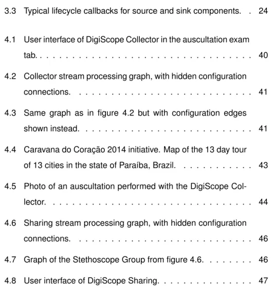
4.1 User interface of DigiScope Collector in the auscultation exam tab. . . 40 4.2 Collector stream processing graph, with hidden configuration
connections. . . 41 4.3 Same graph as in figure 4.2 but with configuration edges
shown instead. . . 41 4.4 Caravana do Coração 2014 initiative. Map of the 13 day tour
of 13 cities in the state of Paraíba, Brazil. . . 43 4.5 Photo of an auscultation performed with the DigiScope
Col-lector. . . 44 4.6 Sharing stream processing graph, with hidden configuration
connections. . . 46 4.7 Graph of the Stethoscope Group from figure 4.6. . . 46 4.8 User interface of DigiScope Sharing. . . 47
4.9 Dra. Juliana (neonatologist) and Dra. Sandra Mattos (pe-diatric cardiologist) using the DigiScope Sharing technology to stream a newborn auscultation sound via a video confer-ence software between the Brazilian cities of João Pessoa (Paraíba) and Recife (Pernambuco). . . 48
Chapter 1
Introduction
Stream processing is present in most applications, even if developers are not explicitly aware of it. A simple XML file parsing can be seen as the pro-cessing of a stream of bytes, in which delimiters are searched for in order to properly structure and recover the encoded information, normally trans-formed again into an application-specific object model. Working on data streams and using files, sockets and similar traditional APIs directly is usu-ally good enough for most applications requiring stream processing. But there are, however, some applications that need, for example, to process streams from various heterogeneous sources and apply several transfor-mations to them. These applications may benefit greatly from a framework that creates abstract layers for these various parts, allowing developers to iterate quickly when testing new algorithms. Such a system would become much more desirable if it was able to achieve these goals not only without degrading a hand rolled implementation to a single thread, but if also able to mutate without stopping entirely.
The main objective of this thesis is to address this problem by propos-ing, a dynamic multi-threaded framework for stream processing. Our chief target is typical desktop computers and mobile devices, instead of large high-end distributed systems. Although this framework has the potential
to impact several communities, in this thesis we will focus on the health community, where a lot of investment is being channeled into telemedicine, home assisted living, assisted support tools and quantified self infrastruc-tures.
1.1
Motivation
When we started this project, we had a framework specialized in imple-menting something akin to a hub. It could send a continuous stream of data, from one device to others. This framework was part of a mobile med-ical learning tool for Android, and started as a way to relay audio from an electronic stethoscope to another, possibly recording it at the same time. The framework provided a way to abstract devices, so we could send the stream without having to worry about the device being a local file or a even a remote device with a complicated protocol stack to communicate with the remote device. This framework was well optimized and worked great, it even was included in other mobile health projects.
Soon we had new requirements. Some devices, most importantly the display, needed to have a filter applied and depending on the source, the audio could need to be downsampled, since the digital stethoscopes only supported a certain sample rate. However the framework proved unfit for those requirements. The source and the destinations were so tightly cou-pled, that it was unable to be extended, so for months that succeeded this, new features were really hacks added where possible to make the end, justify the means.
There had to be a better way. Grouping the audio transformations so we did not had to do the same thing for all stethoscopes would be a win, but we’re determined in not making the same mistake again. We observed that the multiple hops we aspired, could be represented as a directed graph,
CHAPTER 1. INTRODUCTION 3
where the nodes would do some operation on the stream and pass the data to the next node, until it reached a vertice without an outgoing edge.
With this knowledge in mind, we set to work on a generic stream-processing framework that would cater to the current and foreseeable needs of our suite of Android applications, for the medical industry. We envision that a solution to our problem, has a far reaching impact and could be applied to telemedicine, sensor processing and general processing of any data stream.
1.2
Objectives
Aiming at the successful realization of this project, the following milestones were defined:
1. Create a model to abstract operations on a stream, as a black-box with a generic API to compose them together.
2. Attempt to integrate the data source and sink in the same or similar black-box model.
3. Allow new black boxes to be added and other’s to be removed. 4. Make possible to associate context to a data stream.
5. Implement the framework and test in a real world scenario.
1.3
Thesis’s Organization
The rest of this document is organized as follows. Chapter 2, takes a look at the State of the Art in Stream Processing. Chapter 3 starts by briefly explaining the architecture to the predecessor of the work being presented, which followed by the ideas for the framework and the details of the concept
that materialized. On chapter 4, we present two mobile health applications created using this framework and 3 case studies, where the applications were used. Finally, in chapter 5, we revise the state of our goals, possible future work and conclude.
Chapter 2
State of the art
Devising an abstraction for our suite of health applications is not an easy task: one has to maintain an open mind about possible future features and plan according to an ever evolving field, specially when it comes to collect-ing data. Since we are targetcollect-ing Android devices, there’s a strong temp-tation to use Object Oriented Programming (OOP). But the truth is OOP does not “scale“ on a data driven world. Suddenly there is a new device to support, a new protocol stack is built and reality strikes, when finished, it is a different beast with its own internal threading, buffering and memory management and it has more of the same: encoders, decoders, throttling, periodic pinging, . . . It has its own abstractions, that must be abstracted and the result is a lot of extra development time and more resources used at runtime.
We envision a framework that focus on the flow of data, fosters code reuse in the terms of generic modules and is capable of specialization such that we can handle common problems, like threading, throttling and buffer-ing, once and for all. With this is mind, we turned our attention towards applying dataflow and reactive programming methodologies, on top of an OOP language like Java.
Historically, a dataflow program is a directed graph, where data flows 5
between instructions, along its arcs, which represent the program data dependencies [1]. This model shows implicit parallelism, since unrelated nodes may be executed at the same time. Dataflow dates back to 1975 as a competing micro-processor architecture, to the conventional von Neu-mann processors, the architecture is still in use in today’s computers. While dataflow in the hardware has not stood the test of time, it prevailed as a pro-gramming methodology and several variations like reactive propro-gramming, sequential processes and the actor model [2] have been gaining momen-tum.
The remaining of this chapter focuses on three technologies, that are most relevant to a new stream processing framework, based on the flow of data. Although the terminology varies, they may seem very similar differ-ing in their array of features. However it is their features that makes them unique, as some features are impossible to combine together [2].
2.1
Infopipes
Infopipes is a high-level abstraction for information flow [3, 4]. It is based on components with named ports and has support for both push and pull semantics.
A component can have any number of input and output ports (inports and outports). An well formed InfoPipe has information flow from source components to sinks [3], components that have only one outport and in-port respectively. InfoPipes also provides explicit buffer components and pumps, which are basically components representing threads whose job is to make the information flow by pulling upstream and pushing the flow downstream. Given the objective of this abstraction, pumps support throt-tling a stream to achieve a certain rate.
CHAPTER 2. STATE OF THE ART 7
even impossible without them [2]. Regarding InfoPipes, Black et al. ac-knowledges that a cyclic graph allows some useful use-cases and that ex-plicit buffering and a pump may be sufficient to avoid deadlock and infinite recursion [3], however it is not clear if the abstraction allows it or not.
Developers can specify custom components whose ports push and/or pull for new packets, instead of being forced to use one of the modes, de-pending on the component type. To ensure developers can safely mix push and pull components, InfoPipes introduces the concept of polarity on ports: A positive port invokes methods, while a negative port executes methods when invoked [3]. A port is correctly connected to another, when both the flow direction and polarity are the opposite. So data is pushed to a positive inport or pulled by a negative inport, however data must be pulled from a negative outport and a positive outport pushes data to a negative inport. It is interesting to note that InfoPipes supports polymorphic components, whose ports can work in both modes and their polarities (α, α) are inferred from connected components (to either + or −) in a transitive way.
The polarity of ports, the data it accepts and the blocking behavior on (empty or full) queues is described in Typespecs. A Typespec is a metadata container that may contain properties of the flow and QOS parameters. In order to support complex scenarios, like multimedia streaming, Typespecs are extensible, propagate and mutate through the flow. That is, a compo-nent receives a TypeSpec at an inport, adds properties if needed and sends it through all outports [4]. When it reaches a sink, it is sent back through the same path as a reply, allowing components to detect incompatibilities in that path and set an error flag [4].
Generally developers provide processing and control event handlers, however InfoPipes does support active components, that is components that make blocking pull operations on its ports how they see fit. It raises the question about how lifecycle and other control events are received and
handled. The approach taken is that a component can only be handled by one thread at a time and if the thread is blocked in a push or pull operation, it may be preempted to process control events [4]. This may be a problematic for components that synchronize or merge the flow coming through multiple ports, since they need to ensure they can be closed while waiting for input at any of its ports.
One interesting aspect of the C++ middleware described in [4], is the use of coroutines and code generation to make a component implemented to work in a push or pull mode, work in the other mode with a slight per-formance degradation due to extra control flow. Thread style functions are also supported, which maximizes code-reuse and helps adapt legacy code as components.
2.2
CSense
CSense is a Java stream-processing toolkit [5] focused on mobiles devices and high-rate data processing. It features another abstraction using com-ponents with named ports has building blocks, however unlike InfoPipes, the graph is strictly acyclic and relies on static-analysis, at compile time, to verify the correctness of the built graph and detect common errors.
Given that the framework is targeted to systems with restricted resources, CSense takes on a restrictive approach favoring push semantics and a static graph. The frames (packets), that pass through components, belong to memory pools of schedulers. Buffering is built-in and imposes restric-tions on what components can do with that memory. This is done probably to avoid bad practices by programmers, that lead to the garbage collec-tor being called too frequently, which may pause an Android application for several hundreds of milliseconds, especially on older versions. All things considered, CSense promises a safe and optimized environment for static
CHAPTER 2. STATE OF THE ART 9
stream processing applications.
In CSense a component is divided in Modules and Configurations. A module represents the implementation of a component, while Configura-tions are used to configure and connect one or more modules [5]. A minimal module configuration, assigns a data type, possibly with size constraints, to each named port defined in the component and links internal ports (in-put to out(in-put), to ease static analysis. A component is also divided into 3 categories: sources, user components and taps. Frames are created by sources, may be modified by user components and the flow must end in a tap [5].
Components in CSense present mostly push semantics. Pull seman-tics are replaced by pooling requests sent upstream, that may be fulfilled asynchronously and are delivered using push semantics by the associated scheduler.
CSense’s graph, Stream Flow Graph (SFG), is divided into domains. Each domain has an associated scheduler that handles component events sequentially, in the same thread [5]. Additionally the scheduler handles memory management of the frame objects used to pass data to compo-nents. It uses memory pools and the declared size constraints on ports, to determine during static-analysis, the optimal frame/buffer size, which may be shared and sliced through components of that domain, according to their restrictions.
A scheduler is not a component, and so it appears that sources can-not employ blocking pull operations, waiting for new input. This behaviour would have to be adapted to present push semantics and coded externally to the framework, using a Producer-Cosumer model. The CSense source component would act as the consumer, using its scheduler queue to trans-fer data. As an alternative components may request that the scheduler manage NIO (asynchronous IO) selectors for them, pushing new packets
when appropriate. However most libraries in Java use synchronous IO and the Android SDK does not provide a way to use NIO to communicate via Bluetooth and USB, which complicates the integration with CSense.
When being run on Android, the scheduler will automatically use power locks to keep the system from going into deep sleep. For sporadic sens-ing, developers may configure a timeout interval upon the scheduler may release the locks and schedule an alarm to wake up, when the next event is scheduled to run [5]. This is not done by default because the system can take a significant amount of time to wake up.
2.3
Flow Based Programming
Flow Based Programming (FBP) is a relatively old programming methodol-ogy invented by J. Paul Morrison at IBM. Morrison defines FBP as component-oriented networks of black box processes, which exchange data across pre-defined connections by message passing [6]. Those connections are es-tablished externally, using named input and output ports exposed by com-ponents and are specified externally, possibly in a Domain Specific Lan-guage.
The processes are active components that are connected by bounded queues and coordinated by a scheduler [7]. Message passing is done us-ing push semantics, always usus-ing its own outports. The messages changed between connections, Information Packets (IPs), are always ex-clusively owned by the component processing it and must be explicitly de-stroyed when no longer needed, by design, even on garbage-collected en-vironments. Metadata can be added to IPs passing through a connection [7].
The configuration of components should not be done through construc-tors or setters, but rather using dedicated ports. These configuration
pack-CHAPTER 2. STATE OF THE ART 11
ets are called Initial Information Packets (IIPs), since they are expected to be received, only once per configuration port, before receiving IPs for pro-cessing. This technique although it clutters the graph, fosters component reuse by easing the configuration with visual tools. Dynamic configuration is still possible, by having other components send the needed IIPs at exe-cution time, rather than define time [7].
One substantial difference between FBP and the others discussed tech-nologies, is that FBP allows cycles in the graph (but not self-loops), that would allow badly designed networks to deadlock. It also allows grouping of IP’s, by introducing a pair of special control IP’s, called brackets, that open and close substreams [7]. It is normally used with internal component LIFO stacks, provided by most FBP implementations [7].
FBP is not a programming language nor necessarily a framework, but rather a paradigm like Object Oriented Programming. In its most basic form, designing an FBP application can be realized with UNIX pipes to connect different programs to form a “network”. The application, for the Web of Things, described in [8], is a good example of how a FBP system can be implemented in multiple ways and across different programming languages. In this case, the FBP scheduler is the init daemon that just needs to start the processes (and the Linux Kernel scheduler).
2.3.1 JavaFBP
Morrison has open-sourced FBP implementations for C#, C++ and Java and actively maintains them. Since we intend to target Android applications, we thoroughly reviewed JavaFBP, the Java implementation. It consists of an "engine" and an assorted collection of reusable components. A program built with JavaFBP uses a Network Component to define at run-time other components (nodes or sub-networks) and connect their data flow ports.
lifecycle, as it would be expected since it is an FBP implementation. Every Component has its own Java thread and receives messages (Information Packets) by pooling each input port, which may block the thread. Regard-ing metadata, components can specify a description and should statically declare, using annotations, the Input and Output ports that it will be open at runtime.
The implementation of a Network (the Graph) is particularly interesting, since it inherits from Component and is thus a Thread. The components must be defined in a protected method at runtime and it cannot be changed later. Components are also expected to only open ports in the construc-tor. The lack of a dynamic graph severely hinders some use cases, like application-level Multicast: a video-conference where participants may join and leave at any time, would force the Network to be teardown and re-created. However by being threads, Components have greater freedom on their lifecycle and “source components“ can freely pull data using blocking IO.
This library, while it allows a program to be abstracted as a series of reusable components, is not very appropriate for stream processing ap-plications since every node runs as a thread, throughput will suffer from excessive context switching and the lack of memory management optimiza-tions will cause the VM to do somewhat frequent garbage collecoptimiza-tions, which is specially undesirable on mobile devices.
All things considered classical FBP is mostly geared towards business applications [1, 4, 7], its concepts are not always the best fit for high-rate streaming applications that may want to venture into implementing a whole protocol stack, using a “medium-grained” approach and lacks niceties present in less generic frameworks, like flow rate control [4] and memory manage-ment.
CHAPTER 2. STATE OF THE ART 13
2.3.2 NoFlo
NoFlo [9] is an open-source CoffeeScript/JavaScript implementation of FBP. NoFlo is not like the implementations mentioned before, it is not a multi-threaded implementation, although components that perform async oper-ations may be used. After all, JavaScript is mainly single-threaded: asyn-chronous callbacks are the norm, not blocking methods.
Morrison distinguishes NoFlo, from other implementations by calling the latter ones, “Classical FBP”. The biggest difference is that current classical FBP implementations have one thread per node [7] and so, are geared to-wards course-grained modularity [1], while NoFlo’s components and graph feature sequential execution, fomenting more fine-grained components [10] and, in this case, even allowing the graph to be modified dynamically.
Since NoFlo’s Graph and Components all run in the same thread. Event handlers are registered, in components, to process IPs which makes NoFlo effectively a “push implementation” without buffers.
Overall NoFlo has a simpler implementation than most Dataflow frame-works and the simplified concurrency model (or lack thereof) makes NoFlo a very easy platform to quickly prototype a data based or even a generic application for the browser or NodeJS. Theres even an UI, to wire com-ponents, in active development. NoFlo is in fact an interesting platform, however it is not suitable for high-rate stream processing, specially when the data sources and sinks are not natively available on JavaScript.
2.4
Discussion
While all presented technologies have their merits, none of them are par-ticularly well suitable for mobile devices, where the graph needs to be changed often to accommodate new devices that came into range, which would be a common sight in a Wireless Sensor Network. There is a clear
gap for a multi-threaded dataflow framework, based on a dynamic graph, specially one that does not block the flow as a whole, everytime a change needs to be done. A dynamic solution will never be appropriate for every use-case, due to the relatively high cost of updating a graph with such re-quirements and the fact that static analysis of a graph, can have a better understanding of the dataflow, allowing for more aggressive optimizations.
Chapter 3
From Idea to Concept
The idea to create a dataflow-like framework for mobile devices, did not come out out on a whim, but it rather came out of necessity to improve an earlier design, an application-level multicast "router", specialized in audio streams. To better understand the design decisions of the project at hand, we start by taking a look at its predecessor, before detailing the design and architecture.
3.1
Prologue
This framework, creatively called AudioRouter, would connect to multiple devices, assign one as source and send the audio it received from the source to all the other registered devices, the targets.
Developers would only need to implement an interface,AudioConnector, that would allow the framework to connect to the device, retrieve an input or output streams and the audio format. Regarding AudioRouter, a task is created for each Device and a thread is assigned, since retrieving and sending audio is assumed to be a operation that will block.
Internally, the targets wait until the source is ready to inspect the audio format and retrieve a view to the source’s ring buffer. This view object will
Figure 3.1: Typical topology of AudioRouter.
help keep track of the position of the next object and (optionally) block until it is available. The ring buffer itself is lock free, as it only has one Producer. The objects provided by this buffer, are poolable and reference counted byte array wrappers, representing a chunk of audio data, on a read-only contract. This objects are re-used by the source, to minimize garbage col-lection, which can cause pause execution for hundreds of milliseconds, es-pecially on older Android devices.
Thus, since this was implemented in Java, both the buffer and the tar-gets must acquire and release these objects, which explains howAudioRouter is designed as as a single black-box, making extremely hard for developers to, for example, apply a filter to the audio of some devices.
Also in the Android implementation,AudioConnector’s were loaded from an in-house plugin framework and most often than not, they could not han-dle the bitrate or endianness of the audio, if it was not the exact one they suggest in theirAudioFormat’s. So limited support for this type of process-ing, was hacked in AudioRouter, along with rate limiting on sources, for local sound files disguised as devices.
CHAPTER 3. FROM IDEA TO CONCEPT 17
This framework fulfilled its initial requirements and excelled at its job, but with time it became clear that this design would not scale with new requirements.
3.2
The Ideia
We abstract all the stream processing phases in a program into reusable components. These components are black boxes that do some specific operation on the stream and expose a common and generic API. This would allow several of them, to be linked together,forming a program. The data flows naturally through those links, which allows a program to be realized as it was modelled, not like UML but as a directed graph whose nodes are the components.
Furthermore, both the stream source and the data sink should follow the component model. A component could also house a sub-graph, allow-ing complex systems to be simply shown as a sallow-ingle black-box, and at the same time use the framework reusable building blocks to realize its imple-mentation.
Thread handling is probably the most gratifying aspect a stream pro-cessing framework can offer. Aided with metadata provided by developers, we infer the necessities of components and assign schedulers as needed. A scheduler manages part of a graph, specially the packets flowing through its edges, normally providing sequential execution and so backed by a sgle thread. Components cannot communicate to each other directly, in-stead they rely on their schedulers to deliver messages or packets and by doing so, developers can more easily reason about concurrency in the graph.
Finally, the graph is dynamic, allowing components to be added and re-moved at runtime, without stopping the flow. Transactions are provided as
a way to modify the graph, while maintaining consistency. Our goal is to provide an adequate base to build a high-rate stream processing applica-tion for e-health purposes, without trying to cramp every imaginable feature into a smartphone, as it would result in something bloated and hard to use.
3.3
Design and Architecture
Focusing on flexibility and experimentation we approach the architecture by realizing the we’re not providing a solution to a specific problem but rather provide the tools to build solutions to multiple problems, block by block, which will form a directed graph to process data streams. The super-graph of all connected components, is the main entry point that allows compo-nents to be modified on-the-fly and as such our architecture is split between the graph layer and a higher layer that contains the notion of components, ports and ultimately schedulers, that control a series of components.
Decoupling the graph nodes from components, is beneficial as it elimi-nates the burden of having to deal with the intricate of the transaction en-gine, like failed transactions allowing to use different transaction methods, depending on the situation. Furthermore, there is no need for components to implement a cloning method. Components are free to make use of pri-vate state without having to worry if their state is consistent, when someone attempts to clone the component. In this model, it is the graph node that is attached to a component, but the interaction between the two of them ends up being mediated by the component’s scheduler, which in turn reacts to events from a successful transaction.
For the rest of this section, we analyze the various parts of this frame-work, starting with Components, their ports and connections, the role of schedulers and come back to the graph itself, transaction support and life-cycle propagation. We finalize by evaluating concurrency semantics and
CHAPTER 3. FROM IDEA TO CONCEPT 19
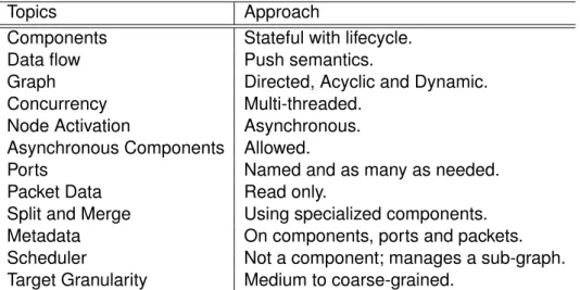
Topics Approach
Components Stateful with lifecycle.
Data flow Push semantics.
Graph Directed, Acyclic and Dynamic.
Concurrency Multi-threaded.
Node Activation Asynchronous.
Asynchronous Components Allowed.
Ports Named and as many as needed.
Packet Data Read only.
Split and Merge Using specialized components.
Metadata On components, ports and packets.
Scheduler Not a component; manages a sub-graph.
Target Granularity Medium to coarse-grained.
Table 3.1: Main topics that we want to tackle and the corresponding ap-proach the we decided to follow.
niceties provided by the framework, like memory management and rate control.
3.3.1 Components
Components make the building blocks of this framework. They are repre-sented by an abstract class, Component, that developers extend to handle packets, lifecycle events and in some cases even introduce new packets into the flow. A component is always executed sequentially. They have ports, that connect to other ports allowing packets to be received or sent, depending on the type of port. They also have metadata, to represent ca-pabilities and restrictions of the component and the flow on its ports.
By itself, components have no function, only when attached to a sched-uler, it becomes active and able to receive and send packets using its own ports. The scheduler is the link between the component and its node in the underlying graph. Ports on the other hand, have no representation in the graph but a connection between two ports, is represented by an edge, using (edge) metadata to make the link.
Components can therefore be classified, regarding their purpose:
• Sources: Have no input ports and produce new packets using data sources external to the framework. Represents, for example, a sensor or a connection to a remote device.
• Processing components: Generic components that processes in-coming data and sends it through an output port.
• Sinks: The flow stops at this type of components, since it does not have output ports. A file or the display, are examples of sinks.
This framework is inherently a push framework. Components don’t pull for new packets, the scheduler pushes them, using its own thread. Compo-nents are expected to either drop the packet, re-send it or process the data and send a different packet, since packet data is read-only. Packets are sent asynchronously to the component on the other end of the port, even within the same scheduler, as its the scheduler that pushes packets.
Using metadata, components can require a more tight relationship with the scheduler. Data has to come from somewhere, so sources components are a bit special. To keep things simple, we would only allow components, to signal the scheduler to asynchronously invoke a component method and push new available data. However, most IO in Java is still done in a block-ing manner and as said before, accommodatblock-ing this use case is important to avoid fragmentation. So components can be made blocking and have the scheduler run a special method, that will be called, basically, in a loop
CHAPTER 3. FROM IDEA TO CONCEPT 21
Components can also hint that they do potential long blocking, like IO, with-out using the looping feature. A variant of this, is components that process packets asynchronously and send packets from external threads. Normally, components with one these features enabled, are never assigned the same scheduler.
We also provide some very simple core components: an explicit packet buffer, a rate limiter and a simple splitter and joiner, since ports can only have one connection. The splitter, with only one input port, sends the re-ceived packet to all output ports, while the joiner is the opposite. To support this use case, the components expose an API method to create a new port with an auto-generated label, allowing to create as many ports as needed. This API is part of the core of the framework, in the form of two interfaces, allowing similar and more specific use-cases to be more easily fulfilled.
Metadata
Metadata allows to provide more information about a component and the data that may flow through its ports. Although its expressiveness is some-what limited, we permit metadata at components, ports and packets, as it provides a generic API that avoids the need to extend classes.
Metadata on components and ports are a part of transactions and com-ponents can use it, to safely pass contextual information to them. Metadata is also used by the framework, as a way to enable special features and it is an important source of data for a graphical user interface, for the wiring of components. On packets, metadata is used as a convenient way to prop-agate related information, that would normally get dropped, by high-level components. Connection metrics, timestamps and sequence numbers and just some useful information that can be stored in metadata.
Metadata is declared in the form of key-value properties, where the keys are always Strings, while values can be of any concrete type but immutable
objects are preferred. To prevent naming clashes and confusion regard-ing provenance, usage of Java’s package namregard-ing conventions on keys is recommended.
We recognize a static metadata system, like Java Annotations, may be easier to work with, when developing a wiring GUI. JavaFBP actually de-clares ports using annotations, and developers attach them at instantiation time. Currently, we have no intention of supporting another metadata sys-tem, since it ends being redundant and a GUI could just instantiate the component and enumerate its ports and metadata keys.
Ports
Components have the ability to expose ports, allowing components to be connected together and send packets. A port can be connected to at most one other port, of a different component. These ports are named, typed (using Java Generics) and can be created at any time. Metadata can be added, providing flow-centric information, that simply is not adequate to describe at the component level.
By default, after a component is added to the graph, no new connec-tions are allowed. This is done, to allow components to be more intelli-gently grouped into schedulers, by not having to worry about possible fu-ture changes to the underlying graph edges. Components that need this freedom, can simply flag so using metadata.
Despite being a multithreaded framework, ports can be created at any time simply because they have no effect until connected. Components can-not connect them, as they do can-not have knowledge of the graph and its state. Ports are connected externally using graph transactions, so changes can be safely applied and propagated. Lifecycle events are sent when a con-nection (between ports) is established or removed, but not when ports are destroyed. Components can enumerate their ports, but for the purpose of
CHAPTER 3. FROM IDEA TO CONCEPT 23
sending and receiving packets, it is the scheduler’s graph that says which ones are connected. In fact there is no way to explicitly destroy a port once created, it is simply left for the garbage collector to dispose of.
Schedulers act as middlemen, by routing packets through ports and maintaining a consistent view of their sub-graph to do so. In a way, ports realize each component specific API while still assuming a very abstract form. Ultimately it is the edges of the lower-level graph layer, that decide what is a valid connected port.
There are two port types: normal and configuration ports. For the most part, this is just a way to clearly differentiate data that is used to initially setup Components from the pipelines used for the data itself. A component may have various ports of this type and configuration ports are expected to only be used once, before receiving data from input ports.
A configuration port, much like a normal port, is still a named and typed port and cannot be connected to normal ports. Configuration ports are in-deed special, because a very minimal flow is expected of them, but also un-like normal ports, a packet can be directly attached to a configuration port. Output configuration ports are also used to configure and propagate con-figuration, that depends on previous flow like remote device negotiation. In some contexts, like multimedia, components should provide a configuration output port to matching a similar input port, in order to facilitate configura-tion of filters and similar components. Components could either propagate the configuration or a splitter could be used to do this, cluttering the graph a little.
It should be noted that components may mark ports as requiring a con-nection to maintain a consistent state. In this case, if a port is connected, all mandatory ports in that component, must also be connected. Compo-nent consistency is checked when a graph transaction is committed and may cause the whole transaction to fail.
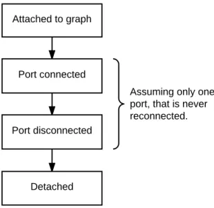
Figure 3.3: Typical lifecycle callbacks for source and sink components.
Lifecycle
Components receive information regarding their lifecycle, in the form of methods called by the scheduler at appropriate times. It is a successful transaction that drives the asynchronous propagation of lifecycle events and notifies the scheduler of a new graph.
As exemplified in figure 3.3, the first lifecycle method is called when at-tached to a graph and consequently to a scheduler. Then it may receive callbacks related to its ports being connected and disconnected. On shut-down or when the component is removed, the port disconnection callbacks are made for all connected ports of a component, before sending the de-tached event. At this stage the component no longer has an associated scheduler and no more callbacks are made, as components cannot be reused.
Lifecycle events are important for resource management. The alterna-tive would be to rely on object instantiation and Java’s finalizers (a method called before the object’s memory is re-collected), which are not very
appro-CHAPTER 3. FROM IDEA TO CONCEPT 25
priate: a component being instantiated may not be used and finalizers can only run after there remains no strong reference, to the object in question. There are various ways that this occurs within normal usage:
• The graph layer must keep strong references to components.
• Schedulers may keep older versions of the graph if their subgraph and connections remain up-to-date.
• Components can be kept in the graph, idle, after all connections are terminated.
Explicit lifecycle is also preferred, because finalizers may be delayed un-predictably and carry a severe performance penalty [11]. They run on the garbage collection thread, increasing the time it takes to complete the sweep.
Composition
Being able to wrap a complex graph, made with multiple components, and offer it as a single black-box with its own set of ports, is an obvious way to present a complex protocol stack implemented using the framework. Schedulers do something similar, they take control of a portion of the com-ponent graph and form a supergraph of schedulers, whose edges represent connections to components, on other schedulers.
AComponentGroup is a special component, that wraps a graph of com-ponents. It provides a familiar API to add components and connect them, but requires developers to explicitly choose which (unconnected) ports are exposed, for use outside the group. This was done, to allow total control over the ports complex systems present as an API, since such systems may have unconnected ports not meant to be part of the external API, but used for debugging.
The wrapped graph is stored as metadata, so it can also be modified as part of a (normal) transaction: if the transaction fails, all internal mod-ifications are transparently lost. Composition works, because the engine recognizes it as a special component at the graph partitioning phase. It is akin to syntactic sugar, since the wrapped graph is retrieved from metadata and theComponentGroup is ignored and not assigned a scheduler.
Another way of achieving composition, would be for a component to internally use a second framework engine, to create a flow graph without knowledge of the first engine. Using transactions, the component would be able to modify the second graph, at any time. However this solution always uses one extra thread, because the second graph has to create at least one scheduler.
3.3.2 Schedulers
Schedulers are the glue between components and threads, keeping the data flowing. Despite the name, a scheduler does not manage threads, it manages a sub-graph of components. Pushing packets is the main duty of a scheduler.
Since each scheduler represents a portion of the flow graph, the set of all schedulers form a super-graph, edges represent connections between components in different schedulers. This high-level view of the informa-tion flow between schedulers, is mainly used by transacinforma-tions to propagate changes. Each scheduler sub-graph is rooted at (at least) one component and all the others, if any, are accessible by following the root’s edges. Most schedulers only have one root, however some specialized schedulers may have more than one. The scheduler knows the root’s ids because of events sent by transactions. It can verify which scheduler that manages a compo-nent, by checking the metadata of the vertex representing it.
CHAPTER 3. FROM IDEA TO CONCEPT 27
graph transaction, being committed. Different scheduler implementations, can co-exist in the same supergraph, since the framework allows both a custom partitioner and default scheduler factory to be set. This would allow, for example, to interoperate with a native C++ port of the framework with a Java layer. If one were to be implemented, a native scheduler could be assigned if, for example, the metadata of all components indicates that they are in fact Java wrappers for native components. As long as it can inspect its sub-graph and handle events, the C++ scheduler could even not have the ability to handle Java components and it would still work, since a scheduler is also a black box like components.
The type of events a scheduler has to handle are lifecycle and graph changes sent by transactions and packet routing sent by its own compo-nents and other schedulers. A scheduler lifecycle starts when it is attached to a graph of schedulers and ends when detached. Like components, once detached, it cannot be reattached.
The lifecycle of components is derived from graph related events. Graph change events require special care, as two events are sent asynchronously by the transaction, to apply the change to components in two distinct stages. The first stage is propagated in topological order to schedulers, using an algorithm suitable for dynamic graphs [12]. In this stage, the scheduler al-ready receives the new graph and sends lifecycle events regarding only disconnected ports and removed components. The second and last stage is sent in reverse topological order, to apply lifecycle callbacks to new com-ponents and connections. It is in this stage, that all modified comcom-ponents (that were not removed), get access to the latest version of their metadata. If a scheduler lost all its components, it will receive a detached event in-stead of the second stage event. Schedulers do not normally need to send callbacks in the same order, since components are not processed concur-rently, while the scheduler reacts to a graph change stage.
A typical scheduler runs off a single thread and uses two FIFO queues. The thread is auto-started, when the first event is queued. The scheduler uses a high-priority queue, for routing events originating from its own thread and the other queue handles everything else, including asynchronous rout-ing requests from "internal" components. When a new packet is received, the receiver component is called to handle it, in the scheduler’s thread. In response, if the component (synchronously) sends packets to its output ports, they go into the high-priority queue and they are sent or handled next regardless of a pending graph change. This way the flow path of a piece of data is kept consistent, throughout its many processing stages. The high-priority queue is essentially an alternative to components not being allowed to send packets directly.
As for limitations, there is no way to safely migrate a component to an-other scheduler. The only way, would be to recreate it and losing its internal state. The graph partitioning is left to make conservative choices on where to place components, like "blocking sources" always having a scheduler for themselves.
3.3.3 Graph Framework
Transactions are the only way to build and modify the flow processing graph in this framework, as they take the graph from one consistent state to the other without blocking the flow. Transactions allow to externally add, re-move and connect components. Components can also make use of the all or nothing allure of transactions, to add metadata added to its representa-tion in the graph, and have it safely propagated to the running component.
The graph transactions are implemented on top of a generic and in-memory, directed acyclic graph framework, developed specially to support the stream-processing use-case. Imaginatively, we call it the graph frame-work.
CHAPTER 3. FROM IDEA TO CONCEPT 29
Graph vertices are indexed by unique identifiers, typed using Java Gener-ics. Edges store a label and the id’s of both the in and out vertices. Fur-thermore, each graph element, be it a vertex, edge or the graph itself has a version number and a generic property/metadata map.
The novelty in this implementation, is that the graph is accessed via a versioned snapshot, that never changes. This is clearly aimed at multi-threaded applications where the reads vastly outnumber the writes, since readers can take the latest snapshot using a volatile read. To modify the graph, one has to resort to starting a transaction and if edges are modi-fied to make the graph cyclic, the transaction will fail at commit time, with an appropriate exception. All graph elements are versioned and they are only copied when needed, since reusing vertices and edges of previous versions, is preferred. This approach is very similar to the concept of Multi Version Concurrency Control [13], implemented by some databases.
Furthermore, the vertices and edges are designed to have no refer-ences to other vertices and depend on the graph’sHashMap to make iter-ation possible. This way reusing elements is in fact beneficial, because it limits the number of objects that are made eligible for garbage collection, without inevitable memory leaks.
Since a graph snapshot is just a triplet containing the version and a map of vertices and properties, the framework allows different transaction implementations to be used. Publishing a new version, is as simple as a compare and swap with the new snapshot. With multiple implementations, one can choose the most adequate depending on the situation. If the graph is, for example, always controlled from a single thread, like in an Android IntentService, the transaction does not need concurrency support at all. If multiple writers are a possibility, we can simply rely on a Lock or imple-ment a fully lock-free transactional solution using logs, to record memory reads and writes. Currently we have an implementation without
concur-rency control and another using a Lock, both without support for nested transactions.
3.3.4 Graph Layer and Transactions
There is no denying that this framework is heavily built around graphs. In fact, we already introduced 3 different graphs: The flattened component graph used by scheduler, the scheduler’s "super-graph" and the user-level component graph. The graph layer, or simply our flow graph is not one graph but a collection of these three graphs, that represent the state at different levels.
Transactions resemble that of the graph framework. The main differ-ence between them, is that in this framework, metadata cannot be modified directly: it is the Component (base class) that given aTransaction, is able to modify its own metadata using protected methods that invoke package-protected methods in the transaction. This is possible because they share the same Java package. The similarity between both the graph layer and component layer transactions is not due to chance. In fact the component’s transaction uses the Bridge pattern [14] to decouple its abstraction from a graph transaction, allowing to use the latter without committing to a certain implementation.
A new transaction exposes the component’s graph to modification and the commit process, needs to perform additional tasks before and after the actual graph commit:
1. Graph flattening 2. Graph partitioning
3. Actual transaction commit 4. Two stage scheduler notification
CHAPTER 3. FROM IDEA TO CONCEPT 31
Those tasks can be skipped if no modifications were made. A transac-tion in that state always commits successfully since it has a consistent view of the graph, even if outdated.
The remaining of this sub-section, goes into detail into each phase that precedes or succeeds the actual graph commit in a commit operation.
Flattening phase
A flattened graph is needed for the partitioning phase, otherwise this phase can be skipped. The graph only needs to be flattened if it contains any ComponentGroup.
If it contains groups, a shallow copy of the graph is made and all groups are replaced by the sub-graph they represent. The edges that were con-nected to the group, are replaced by edges that directly connect to the vertex they represented inside the group.
Partitioning phase
The partitioning phase is responsible for the assignment of schedulers to the flattened graph. It only needs to run, when vertices are added or re-moved.
The Partitioner is another abstract class, a customizable part of the framework. Developers can supply another algorithm to partition the graph and decide what scheduler implementation to use, for each sub-graph. The implementation should be stateless.
A scheduler must be assigned to all components. The Partitioner is required to throw an exception if unable to assign a suitable scheduler to a component. A protected method, must be called with the chosen scheduler for all components, to add mandatory keys to their vertices. Failure to do so, may make schedulers malfunction.
It is thePartitioner responsibility, to maintain the resulting scheduler’s graph snapshot in the component’s graph properties. The graph framework may be used to create the snapshot. No concurrency control is required on the transaction implementation, since we rely on the semantics offered by the component’s graph in-progress transaction. The snapshot should contain the topological order in its metadata. This is required to ease a safer propagation of events to schedulers, due to changes across schedulers. The PK topological sort algorithm [12], provided by the framework, can be used if needed.
The default partitioning algorithm is a bit complex. 1. Start with a source component, not yet visited.
2. For each output connection, check if the other component has an associated scheduler (without marking them as visited). If they do and the vertex is the root of its scheduler, then this source can be added to that scheduler and promoted to root if and only if the change would result in at most one blocking or looping component in the subgraph. 3. If the source was not merged to an existing scheduler, assign it a new
one.
4. Start a depth-first search through the edges of the source. For each vertex found that does not have an assigned scheduler, we check if it is a good match for the last created scheduler:
(a) In the case of a looping component, if the scheduler does not contain a blocking or looping component and if starting from the sub-graph root all components have dynamic connections dis-abled and all connections have the same destination, then a new scheduler is not needed. This is a common topology, where the source components is a controller for the looping component, as as such it should share the same thread.
CHAPTER 3. FROM IDEA TO CONCEPT 33
(b) If it is a blocking sink component, add it to a new scheduler. (c) If it is a non-blocking sink add it to the predecessor’s scheduler. (d) If the previous component was a splitter with normal ports, add
it to a new scheduler to make use of multi-core CPU’s.
(e) If the previous component was a configuration-only splitter, add it to the scheduler’s sub-graph.
(f) If there are no other input edges, also add it to the scheduler’s sub-graph.
(g) Backtrack if the vertex has other input connections that have not been transversed.
(h) Disregarding configuration connections, if other input connec-tions are managed by a different scheduler or (still) not yet vis-ited, then the component is the root of a new scheduler. Other-wise add the component to the current scheduler.
5. Components that remain have no ports. Assign a new scheduler for each one.
Notification phase
The notification phase is the final phase in a transaction. It only happens after a successful commit of the graph. The main purpose of this phase, is to notify schedulers and components of the changes, without requiring schedulers to regularly check for a new graph version.
This phase basically sends the new snapshot to each scheduler, by means of the FIFO queues they use to receive data flow packets from each other. Schedulers are multi-threaded and since there is no global Lock to update them, the changes are not applied from a moment to another, they are propagated. The Queues allows to form happens-before relationships,
between our events and the data flow, so a safe protocol can be devised to update the flow graph.
That is why, the notification phase is divided in two stages. First-stage events are sent in topological order to the schedulers in the old graph. In this stage, schedulers handle removed connections and components. The second stage is sent in reverse topological order, using the new sched-uler’s graph. in this stage, scheduler handle the remaining lifecycle events. Schedulers that are not part of the new graph, receive a detached event. It should be reinforced that the events are processed asynchronously and schedulers may even process incoming flow between stages, from unaf-fected flow paths.
Since not all schedulers receive all three events in this phase, they can infer extra information about their current state. If they did not receive the first stage event, but received the second then their scheduler was just created and if they received the first stage, they know that they’ll either receive the second stage for that graph version or a detach event.
3.3.5 Memory management
Special care is used to avoid creating objects and allocating memory as part of the data flow. The framework provides object pools for generic ob-jects and primitive arrays with fixed capacity. It consists of aPoolManager that manages an optionally bounded, linked-list stack ofPoolableObject’s, using compare and swap. Their usage is optional but highly recommended for high-rate and/or high-bandwidth data streams. The purpose is to avoid triggering the garbage collector, which may pause execution on Android devices, for several hundred milliseconds.
A PoolableObject is an abstract class that doubles as a queue node and as an object wrapper, optionally maintaining a client count that auto-matically returns the object to the pool when all clients release it. Since it
CHAPTER 3. FROM IDEA TO CONCEPT 35
intends to support primitive arrays as well as generic objects, the API does not include a getter nor a setter.
Poolable primitive arrays are mutable, of a fixed capacity and belong to thePoolableObject. The data in them may be of different length, since the implementations provide getters and setters for it. Arrays given by the pool, may optionally be zeroed before being returned to the pool.
A PoolableObject is safe, concurrency wise, as long as the contract is respected. The pool returns an object that can be modified and was not acquired. After setting the data, the client acquires the object and can now safely publish it, but no longer modify it. The publisher, hands-over the object in a read-only contract to consumers, by first acquiring it on their behalf. This is done to ensure, the publisher does not release the object before the consumer can acquire it. When no longer needed, both the consumers and the publisher release the object, which will be return to the pool when no longer in use.
Listing 1: PoolableObject class, documenting the interaction with the pool.
public abstract class PoolableObject { /**
* Used to form a linked-list stack by the PoolManager. * Should be null when not part of a pool.
*/
PoolableObject tail; /**
* Maintains the position in the stack, for bounded * PoolManager's.
*
* If the object at the top has position 4, then there are 5 * elements in the stack. This is always
* (tail.stackPosition + 1) or -1 when null. */
/**
* Pool manager for this wrapper. *
* Uses a WeakReference so garbage collection is not delayed * by a client holding one of these for too long.
*/
private final WeakReference<PoolManager> mManager; /**
* Number of clients using the object (in a read-only * contract) or null.
*
* If non-null a {@link #release()} decrements this and upon * reaching 0 returns the object to the manager.
*/
private final AtomicInteger mClients;
PoolableObject(PoolManager pool, boolean refCount) {/* .. */} /**
* Acquires the object in a read-only contract.
* Note that PoolManager does not pre-acquire objects. *
* This method <i>happens-before</i> a subsequent call to * {@link #acquire()} or {@link #release()}, so a mutable * object, like a byte array, can be modified before * being published.
*/
public void acquire() { /* ... */ } /**
* Releases the object, possibly returning it to the pool. * Do not access the object, after calling this method. *
* This method <i>happens-before</i> a subsequent call to * {@link #acquire()} or {@link #release()}.
*
* @throws IllegalStateException
* If released more times than acquired. */
public void release() { /* ... */ } }
CHAPTER 3. FROM IDEA TO CONCEPT 37
3.4
Resume
In this chapter, we have shown that multi-threaded and complex stream processing, can be done in a flexible and reusable way, by embracing a paradigm shift. A directed graph is a very natural way of describing the flow of data, especially when shown as components with named ports.
We firmly believe that there is a void, to be filled by a dynamic stream-processing framework. Furthermore, we’ve demonstrated that a suitable thread partition can be achieved from a dynamic graph of data processing nodes and that such a graph, can be modified externally, in a safe manner, using a two stage protocol to propagate changes. By using transactions, it was made clear that it is not the data processing that is affected by the runtime overhead of a dynamic solution, but transactions.
Chapter 4
Application in the real world
In this chapter we will present two applications that are strongly based in our dynamic event processing framework, that had, and still has an impact in real world scenarios. We will introduce both applications and their pur-pose, but we will keep focused on the implementation and impact of such a dynamic event processing framework in applications like these two. We will also present some case studies that will emphasize the importance of these applications in the real world.
4.1
DigiScope Collector
Digiscope Collector is an Android application whose purpose is to collect basic physiological information that can be obtained in any standard med-ical appointment, with the benefit of recording the patient’s auscultation exam (see fig. 4.1). Every patient is auscultated in almost every general practitioner appointment, but unlike all the other information that the physi-cian observes or requests, it is not recorded in the electronic health record or any paper version, for that matter. Therefore, we try to fill that gap by providing DigiScope Collector.
The application makes use of an Android Service to provide a central-39
Figure 4.1: User interface of DigiScope Collector in the auscultation exam tab.
ized place to access the stethoscope’s stream processing graph. Clients bind to the service, through a Context instance and receive an asynchronous callback, as a result. The callback is sent by the Android framework, and contains a Binder allowing them to interact with the service.
Using a service instead of a singleton, has a few advantages that we take advantage of:
• Android notifies the Service when all clients disconnect, which allows us to use a timer to disconnect the stethoscope when idle for a long time.
• That notification paired with the lifecycle callbacks, provided by the Service, make it the ideal place to operate a WakeLock. This lock, has nothing to do with concurrency, it prevents the processor from entering a deep sleep, when the screen turns off.
• Allows to give the service a foreground priority, so if the user is multi-tasking, our process is less likely to be killed when memory needs to be freed.
CHAPTER 4. APPLICATION IN THE REAL WORLD 41
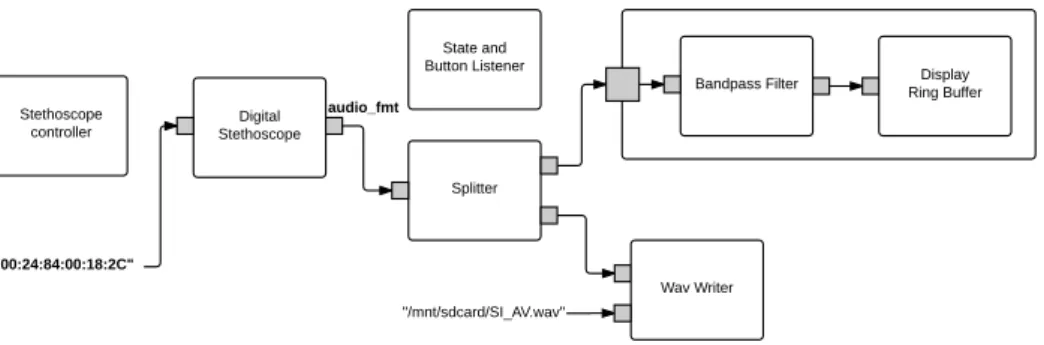
Figure 4.2: Collector stream processing graph, with hidden configuration connections.
Figure 4.3: Same graph as in figure 4.2 but with configuration edges shown instead.
figure 4.2 and is built by the service. Given the Bluetooth address of the digital stethoscope, the service builds the component graph shown in that figure, but initially without the displayComponentGroup and the Wav Writer. When appropriate, clients may ask the service to create them.
The display group uses a bandpass filter and a lock free ring buffer, to allow an OpenGL View, to draw the audio signal, from an “OpenGL thread”. The Wav Writer, on the other hand, writes the audio to a file and is marked as a blocking component. To enable it, clients send the path to save the wav, so the file sink component can be configured, as shown in figure 4.3.
The stethoscope controller component, shown in figure 4.2, allows to change the operating mode of stethoscope. This is an asynchronous con-troller, perfect to allow control of the stethoscope, as a result of user actions
in the user interface. The configuration object, sent to the stethoscope com-ponent, allows to start recording or playback, show a bitmap on the display and block the default actions of some of the stethoscope button’s.
As expected, the stethoscope component, represents the stethoscope’s Bluetooth connection and is a looping component. The splitter just sends the input it receives to all its outports (of the equiparable type). If there is no output connection, the data is simply dropped, except if sent to a configuration port. When faced with configuration packets (see fig. 4.3), it saves the configuration object in case a new component is connected to a (new) output port.
On the other hand, the listener component receives updates about but-ton presses and connection state changes and re-sends them, with the device MAC address, using Android’s broadcasts. The UI is often listening to these events, to notify the user if the connection is lost.
As shown in figure 4.1, the auscultation procedure is actually divided by focal point, making it easy for the application to save one sound file per focal point. This is very helpful when using the sounds for signal processing. One of the stethoscope buttons is used to change focal points. There are also buttons on the UI, to change to a specific focal point, instead of going to the next one, which corroborates the usefulness of the controller/listener combo. The service provides a method to do this focal point transition. It simply uses a transaction to replace the Wav Writer with a new one, pointing using a different file path.
This application has been deployed in several real life scenarios and the design and architecture behind the implementation allowed us to quickly im-prove and update it, taking into account user’s feedback. The following use cases provide a good example of how the deployment of this application is supporting health professionals during their daily work.
CHAPTER 4. APPLICATION IN THE REAL WORLD 43
Figure 4.4: Caravana do Coração 2014 initiative. Map of the 13 day tour of 13 cities in the state of Paraíba, Brazil.
4.1.1 Case Study: Caravana do Coração
In 2011, the state of Paraíba (Brazil) started a cooperation with Real Hos-pital Português, the largest hosHos-pital in northeast Brazil, located in the state of Pernambuco. The goal of this cooperation is to launch a pediatric cardi-ology telemedicine initiative to screen the young population and do it every year. In 2014, this initiative lead to the second edition of the Caravana do Coração tour. In this tour they gathered around 40 multi-disciplinary pro-fessionals (cardiologists, nurses, nutritionist, psychologist, radiologic tech-nologists, information technology staff, researchers, ...) to visit 13 cities of Paraíba, during 13 days and over 2300 km of asphalt, as shown in figure 4.4.
During the 2014 tour 1019 patients, 901 children and 118 pregnant women were screened, with a total of 8152 procedures. They diagnosed 350 patients with cardiac problems, 50 of them were tagged as serious and were referred to the hospital for further analysis. Almost all of the pa-tients auscultations, cardiac and pulmonary, were recorded and stored in the electronic health record of the tour information system. All the