Jaquilino Lopes Silva
Bachelor of Science in Computer ScienceA Distributed Platform for the Volunteer
Execution of Workflows on a Local Area
Network
Thesis submitted in fulfilment of the requirements for the Degree of Master of Science in
Computer Science
Adviser :
Dr. Hervé Miguel Cordeiro Paulino, Assistant
Profes-sor, FCT-UNL
Co-adviser :
Dr. Francisco de Moura e Castro Ascensão de
Azevedo, Assistant Professor, FCT-UNL
Jury:
Chairman: Dr. Nuno Manuel Robalo Correia, Full Professor, FCT-UNL
Main referee: Dr. Paulo Jorge Pires Ferreira, Associate Profes-sor, IST
iii
A Distributed Platform for the Volunteer Execution of Workflows on a Local Area Network
Copyright c Jaquilino Lopes Silva, Faculdade de Ciências e Tecnologia, Universidade Nova de Lisboa
Acknowledgements
Many thanks to Prof. Dr. Hervé Paulino for being my adviser and for all time spent help-ing me durhelp-ing the elaboration of this MSc dissertation. In the same way, I would like to thank my co-adviser Prof. Dr. Francisco Azevedo for having invited Prof. Dr. Hervé Paulino to coordinate this dissertation in collaboration with him and for all supporting. Yours technical background and skills have contributed significantly to the success of this work. You were excellent for me!
I also would like to dedicate this dissertation to all my co-workers from Albatroz Engineering, who supported and advised me whenever I needed to clarify some doubts about system requirements. Special thanks go to Eng. Miguel Ramos, Eng. Tiago Gusmão and Eng. Gomes Mota. Without their supporting may be the realization of this work would not be possible.
Finally, I would like to acknowledge and thank Albatroz Engineering for having par-tially funded this work and provided enough computing resources to test the developed system.
Abstract
Albatroz Engineering has developed a framework for over-head power lines inspec-tion data acquisiinspec-tion and analysis, which includes hardware and software. The frame-work’s software components include inspection data analysis and reporting tools, com-monly known as PLMI2 application/platform.
In PLMI2, the analysis of over-head power line maintenance inspection data consists of a sequence of Automatic Tasks (ATs) interleaved with Manual Tasks (MTs). An AT
consists of a set of algorithms that receives as input one or more datasets, processes them and returns new datasets. In turn, an MT enables human supervisors (also known as lines inspection operators) to correct, improve and validate the results of ATs. ATs run faster than MTs and in the overall work cycle, ATs take less than 10% of total processing time, but still take a few minutes. There is data flow dependency among tasks, which can be modelled with a workflow and even if MTs are omitted from this workflow, it is possible to carry the sequence of ATs, postponing MTs.
In fact, if the computing cost and waiting time are negligible, it may be advantageous to run ATs earlier in the workflow, prior to validation. To address this opportunity, Al-batroz Engineering has invested in a new procedure to stream the data through all ATs fully unattended.
Considering these scenarios, it could be useful to have a system capable of detecting available workstations at a given instant and subsequently distribute the ATs to them. In this way, operators could schedule the execution of future ATs for a given inspection data, while they are performing MTs of another.
The requirements of the system to implement fall within the field Volunteer Comput-ing Systems and we will address some of the challenges posed by these kinds of systems, namely the hosts volatility and failures. Volunteer Computing is a type of distributed computing which exploits idle CPU cycles from computing resources donated by volun-teers and connected through the Internet/Intranet to compute large-scale simulations.
x ABSTRACT
context of Volunteer Computing Systems, able to schedule the ATs of PLMI2 and exploit idle CPU cycles from workstations within the company’s local area network (LAN) to accelerate the data analysis, being aware of data flow interdependencies.
To evaluate the proposed system, a prototype has been implemented, and the simula-tions results have shown that it is scalable and supports fault-tolerance of tasks execution, by employing the rescheduling mechanism.
Resumo
A Albatroz Engenharia SA desenvolveu um sistema de aquisição e análise de da-dos das inspeções de linhas elétricas, que incluihardwareesoftware. Os componentes de
softwareincluem ferramentas de análise e elaboração dos relatórios das inspeções, conhe-cidas como PLMI2.
A análise dos dados de uma inspeção no PLMI2 consiste numa sequência de Tarefas Automáticas (TAs), intercaladas com Tarefas Manuais (TMs).
Uma TA consiste num conjunto de algoritmos que recebem como entrada um ou mais conjuntos de dados, processa-os e cria novos conjuntos de dados. Por sua vez, uma TM permite aos supervisores humanos (também conhecidos como operadores) corrigir, melhorar e validar os resultados das TAs. As TAs executam com maior rapidez do que as TMs, e no ciclo geral de processamento dos dados de uma inspeção, demoram menos de 10% do tempo total, mas ainda na ordem dos minutos. Há uma dependência no fluxo de dados entre as tarefas, que pode ser modelada como umworkflowe se as TMs forem omitidas desteworkflow, é também possível realizar a sequência das TAs, adiando TMs.
De facto, se o custo da computação e o tempo de espera forem desprezáveis, pode ser vantajoso executar as TAs no início doworkflow, antes do processo de validação pe-los operadores. Para abordar essa oportunidade, a Albatroz Engenharia tem investido num novo procedimento alternativo para fazer transmitir os dados entre todas as TAs totalmente autónoma.
Considerando estes cenários, seria útil dispor de um sistema capaz de detetar que as estações de trabalho estão livres num determinado instante e subsequentemente distri-buir as TAs por elas. Deste modo, os operadores poderão agendar a execução das pró-ximas TAs para um determinado conjunto de dados de uma inspeção, enquanto estão a fazer as TMs de um outro conjunto de dados.
xii RESUMO
tira partido de ciclos livres dos recursos de computação doados por voluntários (i.e., os proprietários dos recursos) e que estão ligados através da Internet ou Intranet para a computação de simulações de grande escala. Pretendemos desenvolver um novo sistema de escalonamento de tarefas no contexto dos SCV, capaz de agendar as TAs do PLMI2 e explorar os ciclos livres de CPU das estações de trabalho presentes na rede local da empresa (i.e., na LAN) para acelerar a análise dos dados, tendo em consideração as suas interdependências.
Esta tese propõe e desenha um novo sistema de agendamento distribuído de tarefas no contexto da Computação Voluntária, capaz de agendar as TAs do PLMI2 e explorar os ciclos livres de CPU das estações de trabalho dentro da LAN, para executar essas tarefas, tendo em consideração os requisitos definidos pela Albatroz Engenharia.
Para avaliar o sistema proposto, foi implementado um protótipo e os resultados das simulações mostram que este é escalável e suporta tolerância a falhas na execução das tarefas, recorrendo a um mecanismo de reescalonamento das tarefas.
Contents
Acknowledgements vii
Abstract ix
Resumo xi
1 Introduction 1
1.1 Motivation . . . 3
1.2 Problem Description . . . 4
1.3 Context . . . 6
1.4 Solution . . . 8
1.5 Contributions . . . 8
1.6 Document Organization . . . 9
2 State of the Art 11 2.1 Introduction . . . 11
2.2 Job Scheduling System . . . 12
2.2.1 Scheduling Architectures . . . 13
2.2.2 Resource Discovery. . . 15
2.2.3 Job Scheduling Policy . . . 16
2.2.4 Job Dispatching . . . 18
2.3 Job scheduling in Volunteer Computing Systems . . . 18
2.3.1 Scheduling. . . 19
2.4 Peer-to-Peer Approach to Scheduling. . . 20
2.5 Scheduling of Interdependent Tasks . . . 22
2.6 Discussion . . . 24
3 The Distributed Execution Platform 25 3.1 Requirements . . . 25
xiv CONTENTS
3.3 Task Identification and Contents . . . 29
3.4 Communication: Client-application↔Server-node . . . 29
3.5 Communication: Server-node↔Running Task . . . 32
3.6 Communication: Server-node↔Server-node . . . 33
3.6.1 Master Election . . . 34
3.6.1.1 Fault-tolerance . . . 35
3.6.1.2 Properties . . . 38
3.6.2 Scheduling and Distributed Execution of Tasks. . . 38
3.6.2.1 Fault-tolerance . . . 40
3.6.2.2 Properties and assumptions . . . 42
3.6.3 Server-node Joining/Leaving . . . 43
4 Implementation 45 4.1 Introduction . . . 45
4.2 Task Interface . . . 46
4.3 Integration of a New Task in the System . . . 46
4.4 Inter-tasks Dependencies . . . 47
4.5 Server-node Module . . . 48
4.6 Execution Logging . . . 52
5 Evaluation 55 5.1 Functional Evaluation . . . 55
5.2 Experimental Evaluation . . . 55
5.2.1 Computing Resources . . . 56
5.2.2 Simulation Framework. . . 56
5.2.3 Test Configurations. . . 57
5.2.4 Experimental Results. . . 58
5.3 Non-Functional Requirements Evaluation . . . 61
List of Figures
1.1 A workflow with ATs and MTs intertwined. ATs are outlined with the
green colour and MTs with purple. . . 2
1.2 A general view of the current system architecture. . . 4
1.3 Another possible way to structure the workflow with the MTs on the up-stream. . . 5
2.1 The states of a job.. . . 13
2.2 Centralized scheduling architecture. Adapted from Liet al. [36]. . . 13
2.3 Distributed scheduling architectures. Adapted from Liet al. [36]. . . 14
2.4 Hierarchical scheduling architecture. Adapted from Liet al. [36].. . . 15
2.5 The pull model for resource discovery. Adapted from Liet al. [36].. . . 16
2.6 The push model for resource discovery. Adapted from Liet al. [36]. . . 16
2.7 The push-pull model for resource discovery. Adapted from Liet al. [36]. . 17
2.8 The architecture of PGS. Adapted from Caoet al. [37]. . . 21
3.1 A general view of proposed system architecture. . . 28
3.2 Schedule an automatic task (client-application↔server-node). . . 30
3.3 Subscribing interest in getting the progress and state of a set of tasks (client-application↔server-node). . . 31
3.4 Progress reporting (server-node→client-application). . . 31
3.5 Cancelling the execution of a task (client-application↔server-node). . . . 32
3.6 Progress reporting (running task→server-node). . . 33
3.7 Reporting the final results of a task (running task→server-node ) . . . 33
3.8 Cancelling the execution of a task (server-node↔running task) . . . 34
3.9 An illustration of master election protocol. . . 37
3.10 An illustration of the ENQUEUE protocol.. . . 39
3.11 A system configuration on which can be minimized the race conditions. . 40
xvi LIST OF FIGURES
4.1 Overview of components of a server-node. . . 48
5.1 Workflow used for testing purposes. . . 58
5.2 System scalability with the increasing number of server-nodes.. . . 59
List of Tables
2.1 Description of job state.. . . 12
2.2 A summary of advantages and disadvantages of centralized, distributed and hierarchical scheduling. . . 15
3.1 List of functional requirements . . . 26
3.2 List of non-functional requirements. . . 27
3.3 Format of the messages exchanged between a client-application and server-node. . . 30
3.4 Format of the messages exchanged between a server-node and a running task. . . 32
3.5 Format of the messages used in the master election. . . 35
4.1 Example of dependencies representation among ATs. . . 47
5.1 Functional requirements satisfaction. . . 56
5.2 List of workstations used to test the system. . . 56
5.3 Average makespan in minutes by a workflow for each number of server-nodes in the system. . . 58
5.4 Average waiting time in minutes by a task for each number of server-nodes in the system. . . 59
5.5 Average waiting time by a task and average makespan of a workflow, in minutes, for each number of failed servers. . . 60
List of Algorithms
- Procedure on reception of TTBM( TRY_TO_BE_MASTER reputation map_size timestamp ) . . . 36
- Procedure on reception of SNME( START_NEW_MASTER_ELECTION ) . 36
- Procedure elect master( ) . . . 36
3.1 Master Election . . . 36
- Procedure on CPU idle( ) . . . 41
- Procedure on reception of TD(TRY_DEQUEUE task_uuid timestamp) . . . 41
- Procedure dispatch( ) . . . 41
Listings
4.1 Example of task description file.. . . 47
4.2 Example of the server configuration file. . . 51
1
Introduction
This thesis fits in an enterprise environment, emerging as a real need of Albatroz Engi-neering, a private company dedicated to research, development and innovation in fields such as robotics, aeronautics, software, etc. (see J.Gomes Mota [1] for more details). This company was founded in February 2006 when Gomes Mota and Alberto Vale conceived the Power Line Maintenance Inspection (PLMI) system, which is an innovative, inte-grated, real time, full-featured airborne solution for over-head lines inspection [2].
Since then, Albatroz Engineering has developed a comprehensive framework for over-head power lines inspection data acquisition and analysis [3], that includes hardware (sensors for data acquisition) and software tools. The framework’s software components include inspection data analysis and reporting tools, commonly known as PLMI Fron-tEnd v2.0, abbreviated PLMI2, and one of its main features is the classification of points of interest (PoIs) detected during over-head power line inspections. A point of interest represents an entity (such as a tower, or a tree branch dangerously close to the electrical wires) detected either by a human operator or by an automatic process during a session of data acquisition.
In PLMI2, the analysis of over-head power line maintenance inspection data com-prises a sequence of automatic tasks (ATs) followed by manual tasks (MTs). An AT con-sists of a set of algorithms that receives as input one or more datasets, processes them and returns new datasets. In turn, an MT enables human supervisors (also known as lines inspection operators) to correct, improve and validate the results of ATs.
1. INTRODUCTION
(2) Features extraction (0) Import data
Features validation
(3) Detect PoIs
PoIs validation
(4) Aggregate PoIs
Annotate PoIs
(5) Generate report (1) Georeferencing
B C
D E
A
F
G
H
H
I
I
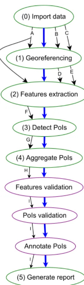
Figure 1.1: A workflow with ATs and MTs intertwined. ATs are outlined with the green colour and MTs with purple.
The data flow dependency is represented by the labelled arrows while the workflow it-self by the blue arrows (the thicker ones). Note that a task may depend on one or more outputs of another, being this determined by the number of edges between them. For instance, the ATFeatures extractiondepends on one output ofImport data(A) and on two of Georeferencing (D andE). The labels A, B, C, and so on, represent the identifiers of output datasets generated in database when a task is executed. The only manual task which may generate a new dataset on database is theFeatures validation. The remaining ones just make changes on existing datasets.
Briefly, for any processing of an inspection data, there are at least the following tasks organized according to a waterfall model:
0 (automatic) Import inspection data (sensors’ data and video) to a centralized database server;
1. INTRODUCTION 1.1. Motivation
server. This task consists in merging acquired data from three sensors, i.e., GPS, IMU1and LiDAR2;
2 (automatic) Features extraction or classification, which is the process of finding power lines, towers, vegetation, buildings, ground, roads and water;
• (manual) Features validation, i.e., the validation of extracted features from the pre-vious task;
3 (automatic) Detection of Points of Interest;
• (manual) Validation of Points of Interest;
4 (automatic) Aggregate Points of Interest according to relevance and maintenance criteria;
• (manual) Add annotations to Points of Interest;
5 (automatic) Generate the inspection analysis report files.
For the first AT, the data to be imported is stored in a local workstation (where the PLMI2 is installed) or else in some location within the company’s Local Area Network (LAN). For the remainder ATs and MTs, the input data is available from the database server. All tasks are performed in a workstation where the PLMI2 application is already installed, and each one of them retrieves data from a central server and stores the subse-quent results in this same server.
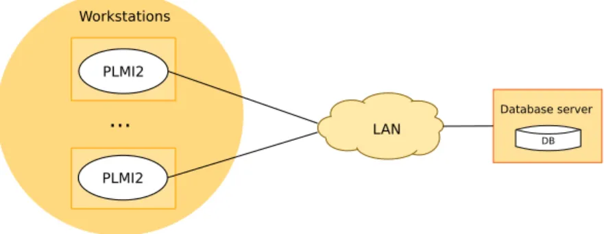
The PLMI2 application is the main entry point to the system, i.e., it is the tool from where the analysis of inspection data is triggered, when an operator requests the execu-tion of the first AT. PLMI2 provides for the processing of the inspecexecu-tion data; for a very rich and complete visualization of the power line and surrounding environment [3], by combining data from different sensors; and for the generation of inspections’ report files. On the other hand, the database server is very simple, i.e., it does not do any com-plex processing. It simply provides a database service to store the large data volumes processed by PLMI2 applications. The system architecture is illustrated in Figure1.2.
1.1
Motivation
Automatic tasks run faster than manual tasks. In the overall work cycle, ATs take less than 10% of total processing time. Each AT takes from 1 to 15 minutes to complete its execution and they are intertwined with MTs. Therefore, the lines inspection operators wait during the execution of ATs but not too much to make it useful to leave the computer unattended to carry other duties.
1http://en.wikipedia.org/wiki/Inertial_measurement_unit
1. INTRODUCTION 1.2. Problem Description
PLMI2 Workstations
PLMI2
... LAN
DB Database server
Figure 1.2: A general view of the current system architecture.
Currently, the PLMI2 enables an operator to request the execution of ATs in several ways. Some restrictions apply, such asImport datamust be the first to be executed and all MTs should be performed before the Generate reportdue to the final inspection’s report quality. Figures1.1(already presented) and1.3depict two different ways to perform the analysis of an inspection data.
Even if MTs are omitted from the workflow, it is possible to carry the sequence of ATs, although with a significant amount of errors. Nevertheless, the quality control tools embedded in PLMI2 highlight these errors which may contribute to a more efficient hu-man validation. In conclusion, if the computing cost and waiting time are negligible it may be advantageous to run ATs earlier in the waterfall stream, prior to validation on the upstream. The configuration depicted in Figure1.3 takes this approach to the extreme performing all automated tasks before manual tasks.
Moreover, even if one maintains the current waterfall model, it may be advantageous to allocate optimal computing resources to execute ATs instead of investing in top per-forming computers for every human operator since the validation tasks do not benefit from the additional computing power and a modest CPU is sufficient.
To address this opportunity, Albatroz Engineering has invested in a new procedure to stream the data through all ATs fully unattended. Depending on the type of power line, this produces between 10% and 70% of correct results before human validation and correction.
1.2
Problem Description
Taking into consideration the scenarios described in the previous section, it may be use-ful to have a system capable to distribute ATs among the available hosts within the com-pany’s Local Area Network (LAN). In this way the lines inspection operators could re-quest the scheduling of next tasks for a given inspection data analysis, to be executed on available hosts, while they are performing manual tasks of another inspection data.
1. INTRODUCTION 1.2. Problem Description
(2)BFeaturesBextraction (0)BImportBdata
(3)BDetectBPoIs
(4)BAggregateBPoIs
(5)BGenerateBreport (1)BGeoreferencing
B C
D E
A
F
G
H
I
I I
AnnotateBPoIs PoIsBvalidation FeaturesBvalidation
Figure 1.3: Another possible way to structure the workflow with the MTs on the up-stream.
of all possible combinations of ATs for any inspection data analysis, either during day-time or night-day-time, by exploiting idle CPU cycles from the workers’ workstations within the LAN and consequently minimizing the time that lines inspection operators wait for ATs results to be available
It is necessary to design and implement a system able to detect that the hosts are available at a given instant and subsequently distribute the automatic tasks to them. In addition to the task’s execution, this system should be aware of their inter-dependencies, as explained in Section1.1. Moreover, operators may want to prioritize the execution of tasks of a workflow relatively to tasks of another workflows. Therefore, when an operator requests the execution of a task, the system may execute it immediately or not, according to its priority and the number of other tasks that are waiting to be executed.
Computing resources should be able to execute ATs, either in a batch processing mode (which will be useful, for instance, during night-time because the company has several hosts that are stopped overnight), or in a screensaver-like mode, which will exploit idle CPU cycles from computing resources during lunch hours, meetings, etc., to accelerate the inspection data analysis.
1. INTRODUCTION 1.3. Context
some of the challenges posed by these systems, such as hosts volatility (i.e., a host may join and leave the system any time it wants) and heterogeneity, i.e., hosts have different operating systems, CPU type, RAM size, etc.
1.3
Context
Volunteer Computing (VC) is a type of distributed computing in which computer owners (i.e., the volunteers) provide their computing resources, such as idle CPU cycles, storage and Internet bandwidth, for scientific projects, which use these resources to distribute the computing of large-scale processes, such as simulations. The termvolunteer comput-ingwas introduced by Luis F. G. Sarmenta in his Ph.D. thesis in 2001 [4]. The first VC project was the Great Internet Mersenne Prime Search (GIMPS) [5], which searches for Mersenne prime numbers and began in 1996. One year later, in 1997 the Distributed.net was founded, which is a general-purpose distributed computing project where thou-sands of users around the world donate the power of their personal computers to aca-demic research and public-interest projects [6]. The SETI@home [7], since its release in 1999, has demonstrated the great potential of VC. SETI@home is an Internet-based public VC project with the purpose of analysing radio signals, searching for signs of extraterres-trial intelligence [8].
One of the main advantages of volunteer computing over traditional solutions based on supercomputers is the fact that it is not expensive. However, the development of VC projects needs to address some problems and challenges in order to provide high-throughput computing. The big challenge in Volunteer Computing Systems (VCSs) is the scheduling of work-units in highly dynamic environment composed of multiple het-erogeneous computers, as stated in [9]; and the common problem to address in these systems is the distributed resources management [10].
On the first viewpoint, one might sense that VC is restricted only to systems where computing resources are located in the scope of the Internet, but not necessarily, since people within an organization (i.e., within a LAN) can also volunteer their workstations during idle time, in the same way as Internet users volunteer theirs. Indeed, an impor-tant aspect emphasized by L. Sarmenta in [11], is that volunteer computing can be used not only for building a wide area network (WAN) of parallel computing more power-ful than a supercomputer but it also can be employed even for small scale environments, such as companies or institutions, to exploit the power of workstations to provide similar solutions like a supercomputer.
1. INTRODUCTION 1.3. Context
related with reliability (e.g., trying to protect the system against malicious volunteers) as identified and discussed in [4].
The resources in the company’s LAN are heterogeneous (e.g., operating system, CPU, memory, availability, volatility, etc.) and the degree of their volatility is very high during the day (when needed, some of them keep running during the night), meaning that the system should address these problems because the heterogeneity may delay the overall tasks execution time and/or make the scheduling decisions more difficult.
We intend to implement a system with the following features:
1. A distributed execution system and decentralized;
2. Execution of workflows of tasks;
3. Volunteer Computing-based;
4. Directed to the LANs;
5. Resilient to the nodes failures (fail-stop model, not Byzantine failures);
Volunteer Computing systems for the Internet, such as SETI@home [7] or those sys-tems based on BOINC middleware [13], are resilient to the failures, take into account hosts heterogeneity, volatility, etc., but they are all centralized.
Systems based on Desktop Grid Computing (DGC), which is a type of distributed sys-tem that uses computing, network, and storage resources of idle desktop PCs distributed over multiple LANs or the Internet [14], are volunteer-based, operate within a LAN or interconnect LANs but we have not found none of them which has simultaneously all features that the system we propose should have.
At the moment of this writing, the Condor [12,15, 16], which is a DGC system that manages clusters of desktop workstations, supports execution of dependent or indepen-dent jobs/tasks, provides supporting for fault-tolerance, addresses challenges such as resources volatility, heterogeneity, etc., is directed either to LAN or Internet, is the only system that supports the majority of features provided by our proposed system, but its current release has some limitations3on jobs which use checkpointing as mechanism for the fault-tolerance supporting and it relies on a single central manager.
For example, the system proposed in [17] follows a peer-to-peer scheduling archi-tecture, takes into account the hosts’ heterogeneity when it makes scheduling decisions and harvests night-time idle cycles from desktop computers distributed geographically in different time zones over the Internet, but does not consider tasks with dependencies. The system presented in [18] follows a peer-to-peer based Volunteer Computing ar-chitecture, i.e., a decentralized scheduling model, but does not support fault-tolerance.
Entropia [19] is a DGC system directed to LAN or Internet, which addresses a number of challenging issues, such as fault-tolerance supporting, scalability, robustness, etc., but does not consider the scheduling of tasks/jobs containing dependencies.
1. INTRODUCTION 1.4. Solution
Regarding distributed scheduling algorithms in the context of Volunteer Computing, currently, it may be found research works such as:
• For example, [20] is a fully distributed scheduling algorithm which takes into con-sideration several issues, such as scheduling interdependent tasks of DAG and ex-ploits idle CPU cycles, but it lacks of fault-tolerance supporting of task execution;
• The decentralized scheduling algorithmCoAllocationproposed in [21], for schedul-ing tasks havschedul-ing dependencies in Grid environments, which tries to achieve the load-balancing in terms of number of tasks scheduled in each computing resource, yields good results, but lacks of the fault-tolerance supporting.
1.4
Solution
We developed a new task scheduling system in the context of Volunteer Computing Sys-tems, able to schedule simulated automatic tasks of PLMI2 and exploit the idle CPU cy-cles from hosts within Albatroz Engineering’s LAN to accelerate the data analysis, being aware of their inter-dependencies and priorities. These tasks are executed by the com-pany’s computing resources either in a batch processing mode or in a screensaver-like mode. This system follows a distributed scheduling architecture, on which each sched-uler may have either the role of server and/or client; which does not rely on the process of computing resources discovery such as pull and push modes (defined later in Subsec-tion2.2.2) because all schedulers are supposed to have the same set of tasks and when a scheduler’s host becomes idle it just asks other servers if it can start executing a given task.
The main challenges of this thesis are:
• Dealing with the data flow dependency among tasks, i.e., how to represent that an automatic task depends on the results of other tasks which have not finished yet their executions, meaning that an AT should only start its execution once its dependable tasks have processed the data on which it depends on. In other words, tasks are organized in an assembly-like manner, where the output of a task is fed to following tasks;
• Dealing with the computing resources volatility, i.e., they may join or leave the system unexpectedly;
• The implementation of a distributed system with fault-tolerance supporting.
1.5
Contributions
1. INTRODUCTION 1.6. Document Organization
• The design of a system fully distributed, able to meet the requirements defined by Albatroz Engineering, namely the scheduling of tasks of a workflow within a LAN following a Volunteer Computing model;
• Implementation of a prototype of the proposed system;
• Evaluation of the system scalability and its ability for fault-tolerance supporting;
• Evaluation of the average waiting time by a task, i.e., the time since it becomes ready to be executed until the system starts executing it and the average completion time of a workflow.
1.6
Document Organization
This document has six chapters organized as follows:
• Chapter1introduces us to the problem, its motivations and challenges.
• Chapter2discusses what is a job scheduling system, what are the common schedul-ing architectures employed, how the computschedul-ing resources are discovered and fi-nally presents the related works from state-of-the-art.
• In Chapter3, we present the system requirements, the communication protocols among its entities, the algorithms for achieving the distributed scheduling and its architecture.
• Chapter4explains in details how a system prototype was implemented.
• In Chapter5, we describe how it was developed a simulation framework to auto-matically test the prototype and we present the results obtained by evaluating it with different test configurations. We also provide an evaluation of the require-ments satisfaction by our developed prototype.
2
State of the Art
This chapter briefly presents a literature overview of existing job scheduling systems, in which we define and discuss several issues related to this field of study. Concretely, we present the common architectures employed by existing scheduling systems, their advantages and disadvantages taking into consideration the requirements of a given job scheduling problem. We also talk about the scheduling for Volunteer Computing, its main challenges and problems. Furthermore, this chapter presents some of close re-lated works from state-of-the-art, namely the scheduling in Peer-to-Peer systems. Finally, this chapter ends with a brief discussion about the scheduling systems and what are the mechanisms that our system will employ.
2.1
Introduction
The scheduling problem is not new in the field of distributed computing systems. It has been a subject of study for more than two decades; hence, several solutions to solve this problem in an effective way have been proposed in the field of Artificial Intelligence, often based on genetic algorithms and heuristic search strategies [9,22,23,24]. A con-siderable number of researches have been done in order to categorize the field [4,10,12,
25] and several systems addressing this problem have been implemented in real-world scenarios [7,11,15,26,27].
2. STATE OF THEART 2.2. Job Scheduling System
Sate Description
Submitted The job was submitted to the scheduler and is waiting in the job queue for its turn to be processed, according to its type, priority and resources it needs, then going to Ready state.
Ready The job is waiting in the ready job queue to be assigned to the execution host.
Scheduled The job was dispatched to the execution host.
Running The job is being executed.
Suspended The job was interrupted, either explicitly by a user through an exter-nal command or the job suspended itself waiting for some condition to allow it to proceed.
Cancelled The job was cancelled (e.g., by a user).
Aborted The job was aborted due to an internal system error.
Terminated The job has finished execution.
Table 2.1: Description of job state.
presented in Section2.4. Section2.5presents two related works concerning the schedul-ing of tasks with dependencies and provides references to more related works. Finally, a general discussion about what techniques will be applied by our system is presented in Section2.6
2.2
Job Scheduling System
This section gives a general overview of what a scheduling system is about and how it works in the context of distributed computing systems.
Job scheduling is defined as the process of mapping jobs for execution into available computing resources. The concept ofjobis not clearly defined in state-of-the-art, thus in the context of this research we will define it has being a unit of computational work to be performed. Some research papers [21,28] consider that it can be split in many small tasks, but in our case we will consider a job as being the same as atask, and these terms may be used interchangeably. Aresourcewill be considered as any computer in the LAN with minimum required features to run a job.
2. STATE OF THEART 2.2. Job Scheduling System
Submitted Ready Scheduled Running
Aborted
Suspended Cancelled
Terminated
Figure 2.1: The states of a job.
central scheduler
jobs
job1
job2 job3
node2
node1 node3
Figure 2.2: Centralized scheduling architecture. Adapted from Liet al. [36].
books, for example in [29,30,31], or found in [32,33,34]. Note that a job goes into Sub-mitted, Suspended or Cancelled state by a user’s action while the remainder transitions are triggered by the scheduling system.
2.2.1 Scheduling Architectures
When designing and developing a scheduling system, the designers should consider the following architectures according to where and how the scheduling decision is made. There are three proposed architectures [12,35], centralized, distributed and hierarchical, which are detailed below.
Centralized scheduling: In this architecture, there is only one scheduler that is respon-sible for making all decisions, i.e., how to select a job and to which resource it will be scheduled. This approach is illustrated in Figure2.2.
2. STATE OF THEART 2.2. Job Scheduling System local resources local resources local resources local resources scheduler1 scheduler3 scheduler4 scheduler2 jobs jobs jobs jobs jobs jobs
(a) Distributed scheduling with direct communication between sched-ulers. local resources scheduler3 scheduler1 scheduler2 jobs jobs jobs jobs jobs jobs Job pool local resources local resources
(b) Distributed scheduling with indirect communication be-tween schedulers via job pool.
Figure 2.3: Distributed scheduling architectures. Adapted from Liet al. [36].
can be divided in two sub-types [36], namely (1)direct communicationand (2)indirect communication via job pool. In (1) each scheduling process features a list of it peers to whom it can communicate with. When it cannot schedule a given job locally then it sends the job to other schedulers as shown in Figure 2.3(a), whereas in (2), illustrated in Figure 2.3(b), when a job cannot be locally scheduled, then it is placed on a job pool to be scheduled by other and therefore the schedulers’ policies should ensure that all submitted jobs to the job pool eventually will be executed.
Hierarchical scheduling: In this approach, jobs are submitted to a central node, which dispatches them to local schedulers, whereas each local scheduler submits jobs to its com-puting resources. Figure2.4depicts this approach.
2. STATE OF THEART 2.2. Job Scheduling System local resources central scheduler local
scheduler1 scheduler2local jobs
jobs jobs
local resources
Figure 2.4: Hierarchical scheduling architecture. Adapted from Liet al. [36].
Architecture Advantages Disadvantages
Centralized - Makes better scheduling deci-sions because the scheduler has access to all information about all resources.
- Single point of failure;
- Does not scale well with the in-creasing of number of resources.
Distributed - Scalable;
- Can offer better fault tolerance and reliability.
- The lack of a global scheduler, that knows all system informa-tion, may lead to sub-optimal scheduling decisions.
Hierarchical - Global scheduler and local scheduler can have different policies in selecting jobs or re-sources.
- The central scheduler can have scalability and communication bottlenecks because it is a sin-gle instance to which all jobs are firstly submitted.
Table 2.2: A summary of advantages and disadvantages of centralized, distributed and hierarchical scheduling.
2.2.2 Resource Discovery
The resource discovery consists in finding suitable resources from an available set of them, for executing jobs. The information that is passed from resources to the scheduler are CPU speed and current load, available memory, etc. The resource discovery might be performed by three models, i.e., the pull model, push and push-pull, as proposed by Li
et al.[36].
The pull model: A daemon process associated with the scheduler is responsible for requesting/pulling state information from resources. Figure2.5depicts this model.
2. STATE OF THEART 2.2. Job Scheduling System
daemon scheduler
node1 node2
node information node information
Figure 2.5: The pull model for resource discovery. Adapted from Liet al. [36].
daemon daemon
Node State scheduler
node1 node2
node information node information
Figure 2.6: The push model for resource discovery. Adapted from Liet al. [36].
scheduling algorithm. Figure2.6illustrates this model.
The push-pull model: This model is a combination of pull and push strategies, i.e., there is a daemon process in the central scheduler, who pulls information from aggrega-tors, and there are daemons in nodes/resources whom collect and push state information to the daemon process of a known aggregator, which is responsible for aggregating in-formation from a set of resources and replying queries from the scheduler. This strategy for resource discovery is shown in Figure2.7.
Resource discovery in distributed scheduling: Note that, the previously described re-source discovery mechanisms apply not only to the centralized but also to distributed scheduling. But usually in decentralized environments the discovery is accomplished by a central entity (e.g., the Grid Peer Information Service in [37]), which itself can be imple-mented either as centralized or decentralized. The latter case might be more challenging because it is necessary to keep all its replicas coherent.
2.2.3 Job Scheduling Policy
The process of selecting the next job from a queue to be scheduled is accomplished by using a dedicated algorithm namedscheduling policy.
2. STATE OF THEART 2.2. Job Scheduling System
daemon
daemon daemon
daemon
daemon
daemon scheduler
aggregator aggregator
node2
node1 node3
node information
node information node information
Figure 2.7: The push-pull model for resource discovery. Adapted from Liet al. [36].
up one resource to execute the chosen job, from an available set of resources. Or even more concrete, what is the matching job-resource that would minimize the overall jobs execution time.
The problem of mapping jobs into distributed resources in a way that minimizes the
makespan(the total execution time), has shown to be NP-complete, by a reduction from the Minimum Multiprocessor Scheduling [38]. What can be done is to find sub-optimal solutions by using strategies based on heuristic search.
Choiet al. [12] classified the scheduling policy in three approaches, i.e., simple, model-based and heuristic-model-based.
Simple approach The common and simple strategy [12,39] consists in selecting jobs or resources with the First Come First Serve (FCFS) method, which can be imple-mented with a well-known data structure, the FIFO (First In First Out) queue, or a random approach, which is implement by techniques of random numbers gener-ation.
Model-based This approach is divided in three main categories, namely deterministic, probabilistic or economy model.
In deterministic model, jobs or resources are selected according to a predefined structure or topology of their organization, that is, how the jobs or resources are in-terconnected with each other. The common structures or topologies are the queue, stack, graph and the ring. In comparison, inprobabilistic model, jobs or resources are selected according to probability theory (e.g., using the Markov model as ap-plied in [40]).
2. STATE OF THEART 2.3. Job scheduling in Volunteer Computing Systems
There are other scheduling policies that were not mentioned above, which are those based on priority of jobs. Examples are pre-emptive scheduling, which lets a pending high-priority job to take resources away from an executing job of lower priority, and
shortest job first (SJF), in which the next job to be scheduled is the one that has minimum estimated completion time (ECT); if two jobs have the same ECT then FCFS is applied.
A well-known problem of priority-based scheduling isstarvation, i.e., a job that is ready to run can never be scheduled because high-priority jobs are always selected first even when they arrive after that job. A solution to solve this problem is to applyageing, which is a technique of gradually increasing the priority of jobs that wait in the system for a long time [31].
2.2.4 Job Dispatching
It is the process of assigning the execution of next job to run on the selected resource. It can also be performed according to the pull and push modes [36], described as follows:
Pull mode: The resources pull jobs from scheduler when they go into idle time and then the scheduler assigns jobs to them according to its scheduling policy. This mode is suitable for those systems where resources arevolatile, i.e.,non-dedicated[12,41].
Push mode: The scheduler starts the scheduling process when jobs are submitted to its queue, that is, it pushes jobs to resources according to its scheduling policy. The push mode can be suitable for systems whose the probability of a resource being in idle state is very low (in this case, the resources are calleddedicated resourcesas defined in [12,41]).
An example of a scheduling system that employs similar mechanisms is the Condor [15]. It allocates resources for job dispatching by employing a matchmaking mechanism. This mechanism is based upon notion that jobs and resources advertise themselves in
classified advertising (abbreviated ClassAds), which include their characteristics and requirements, then each pair job-resource that matches is created.
2.3
Job scheduling in Volunteer Computing Systems
2. STATE OF THEART 2.3. Job scheduling in Volunteer Computing Systems
Fault tolerance: It is a common non-functional requirement found in many computing systems, which enables a system to work properly even if some of its part fails [43]. In the context this work, it can be considered as a quality attribute that tolerates resource failures and volatility. The rescheduling, checkpoint-restart, replication of tasks, etc., are the common applied techniques for leading with these failures [12]. For therescheduling technique, if a scheduler detects a resource failure then it reassigns the failed task to another resource. For thecheckpoint-restart, the scheduler restarts the failed task from the checkpoint in another resource. For thereplication, a scheduler replicates a task on multiple resources, to allow a resource to mask the failure of another.
Load balancing: In the context of VCSs, this property attempts to balance the compu-tation load among computing resources present in the system. Normally, the system’s lightly loaded nodes cooperate to remove the work in heavily loaded node by exchang-ing information (periodically or on demand) about their characteristics and current CPU load. This property can be accomplished by applying the pull mode for the workstealing
or the push mode for the load distribution.
2.3.1 Scheduling
Recently, many scheduling policies based on heuristics (e.g., HEFT, min-min, max-min, and so on [44]) have been proposed in the context of VCSs because the problem of opti-mal mapping of tasks to resources is NP-complete as already mentioned previously, thus these heuristics try to find sub-optimal mapping.
The pull approach (presented in Subsection 2.2.4) is the common dispatching mode employed by the VCSs, i.e., when volunteers go into idle state then they contact a VC job scheduler, requesting for the jobs for the execution. As an example, the BOINC’s local scheduling [45] employs this mode. BOINC (Berkeley Open Infrastructure for Net-work Computing) is an open source middleware system for VCSs [13] used in several VC projects (e.g., SETI@home [7], FightAIDS@home [27], Folding@home [26], etc.).
As stated by Estradaet al.in [9], existing job dispatching policies in VC projects can be classified in two classes, i.e., naive and knowledge-based. Examples ofnaiveapproaches are FCFS, the random allocation and the locality assignment in which jobs are assigned preferentially to volunteers that already have necessary data to accomplish the execution. In contrast,knowledge-basedapproach takes into account the historical behaviour of the volunteers when assign jobs to them.
2. STATE OF THEART 2.4. Peer-to-Peer Approach to Scheduling
This method includes a genetic algorithm in which the representation of individuals, fit-ness function, and genetic operators are tailored to get effective policies that are project-independent, minimize errors, and maximize throughput in VC projects. However, some input values to the algorithm are manually introduced and they intend to automate this process in future work.
In [43], Leeet al. addressed the problem of robust task scheduling in VCSs by propos-ing two heuristics, which identifies best task-resource matches in terms of makespan and robustness. Generally, the robustnessis defined as the capacity to function properly in variable conditions. As the context of the research was VCSs, the definition of robustness was narrowed down to the ability to ensure the quality of a schedule in spite of a certain degree of performance fluctuations, such as inaccurate estimative of task completion time and resource performance degradation. For a given schedule, both proposed algorithms,
RMAX and RMXMN, aim to reschedule it, if a new task-resource match improves the robustness without increasing the makespan.
Extensive set of experiments allowed to conclude that the robustness of output sched-ules is improved by maximizing either the total or minimum relative delay time over all allocated VC resources.
2.4
Peer-to-Peer Approach to Scheduling
This section overviews two related works concerning the scheduling in P2P1 systems. The reason why we are presenting these systems, is because we intend to developed a distributed job scheduling where each node can provide both client and server function-alities.
Caoet al. [37] in their research entitledA Peer-to-Peer Approach to Task Scheduling pro-posed a P2P approach which employs the distributed scheduling architecture to lessen the load of intermediate server by letting the peers to cooperate among them to make scheduling decisions using their own scheduling policies. Each scheduler running on a peer follows a generic architecture which authors denominated PGS (P2P Grid Sched-uler) and jobs are firstly submitted to the local scheduler where they originated. Each peer interacts with GPIS for collecting information about other peers and making schedul-ing decisions. Once a scheduler has decided to/from which peer it should dispatch/re-quest jobs, then starts to interact directly with it through Peer Communication compo-nent.
The system relies on a Grid Peer Information Service (GPIS) based on Grid Informa-tion Service (GIS2). The GPIS provides information about peers in the system and it is a meta-data infrastructure that enhances existing GIS in Grid middleware. As the authors stated, in Grid environment the GIS gets outdated very quickly, because nodes are freely
1The termpeer-to-peer(P2P) refers to a class of systems and applications that employ distributed
re-sources to perform a function in a decentralized manner [46]. 2
2. STATE OF THEART 2.4. Peer-to-Peer Approach to Scheduling
GPIS
Dispatcher System
Monitor Scheduler Reporter
Enquirer
Process Monitor
Collector Execution
queue Application
Communication
Grid Communication
Peer Communication Task
Grid
PGS
Figure 2.8: The architecture of PGS. Adapted from Caoet al. [37].
to join and leave at any time, and due to possible system failures. Figure2.8illustrates the PGS architecture installed on every peer. The components that compose the PGS are the following:
Grid Communication It is a communication interface between GPIS and PGS’s compo-nents to allow a peer to query information about other peers kept by GPIS.
Application Communication It is an interface to enables user to provide resource de-tails, to edit GPIS and specify scheduling policies.
System Monitor It is responsible for gathering quality information (either periodically or on the demand) about a peer (i.e., CPU load, available RAM, etc.) and translating it into readable format to be used in resource selection process.
Scheduler The component responsible for scheduling tasks of submitted jobs, by re-questing a group of peers from the GPIS and consulting the System Monitor to get peer information, and according to the scheduling policy it decides if a task will be executed locally or remotely.
Dispatcher It is responsible for dispatching tasks of a job to other peers when peer is busy.
2. STATE OF THEART 2.5. Scheduling of Interdependent Tasks
Process Monitor The component responsible for monitoring the tasks that are being ex-ecuted locally.
Reporter It is responsible for gathering the tasks’ status from Process Monitor when inquired by other peers.
Enquirer The component responsible for requesting tasks’ status information from re-mote peers.
The process of scheduling in PGS is composed by peers registration in GPIS, task scheduling and task execution. The task scheduling is divided in task capturing and task dispatching. Task capturing uses push mode, whereas task dispatching employs pull mode.
The proposed architecture was implemented and the performed experiments allowed to conclude that combination of push and pull modes for task dispatching achieved faster convergence in speedup than only push mode.
Zhaoet al. [18] proposed a system namedPPVC: A P2P Volunteer Computing System, for job scheduling, in which volunteers are organized as a P2P network, i.e., there is no central server and every volunteer has the same functionality.
In order to use several computers in the network, a job should be able to be recursively separable into small sub-jobs. When a peer receives a job, he splits it inN + 1sub-jobs, whereNis the number of its neighbours that are free. One sub-job is executed locally and remaining will be sent to N free neighbours. A job is split until not possible to be split any more or if a peer has no available neighbour. When a peer completes the execution of a job, the result is sent to its parent to be collected and merged with other results. The system supports the dynamic joining and leaving of peers, by self-reorganization of its grid.
The authors implemented the PPVC using Java platform and the case of study was N-Queen problem. The experiments were conducted by using three computers and the results shown that the efficiency in terms of system’s response time with three peers, for 14-Queen was 87.5%, 15-Queen was 88.1% and 16-Queen was 89.9%, respectively.
2.5
Scheduling of Interdependent Tasks
2. STATE OF THEART 2.5. Scheduling of Interdependent Tasks
Blytheet al. [50] proposed two classes of resources allocation algorithms: task-based approach (TBA) and workflow-based approach (WBA). The jobs/tasks in a workflow have well-defined dependencies of required input data to allow the computing. TBA greedily assigns each ready to run task to a resource regarding only the information about that task, i.e., it only reasons about the tasks that are ready to run at any given time instant, whereas WBA searches for an efficient allocation of entire workflow, and may revise the allocation of a task based on subsequent tasks. The performed simulations al-lowed the authors to conclude that both approaches are suitable for computing-intensive workflows but WBA is more suitable for data-intensive workflows because it decreases the time to transfer data from one task to another.
Moiseet al.[21] proposed a scheduling algorithm namedCoAllocation, for scheduling tasks having dependencies, which is a decentralized, dynamic and optimal mechanism for job scheduling in Grid environments. CoAllocation consists in allocating tasks hav-ing dependencies, in which the main purpose consists in generathav-ing schedules in efficient way, in terms of load balancing among computing resources and minimum time for exe-cution of tasks. Tasks and computing resources are described by using the XML format.
A set of tasks is represented with a weighted DAG, in which each node represents a task and the dependency between two tasks is represented by an edge. A weight on edge means the cost in terms of time to transfer information between two tasks and a weight on a node is the cost in terms of time to execute a task.
The CoAllocation algorithm involves two types of entities, called broker and agent, defined as follows:
Broker This entity is responsible for receiving an XML file containing tasks’ dependen-cies from a user, clustering of tasks and distributing each formed cluster to each agent.
Agent It is an entity responsible for managing a set of local computing resources.
The CoAllocation algorithm comprises three phases, which are described below:
Task clustering This phase consists in creating a DAG of sub-DAGs of tasks having de-pendencies, on which each a sub-DAG is connected to another if there is a depen-dency between one of its tasks and another tasks of other sub-DAG.
Dynamic scheduling inside a cluster (i.e., a sub-DAG) It consists in scheduling tasks to an agent’s local computing resources.
Dynamic scheduling of clusters It is the final scheduling, that will be done by the bro-ker, of the DAG of clusters based on the dependencies between them.
2. STATE OF THEART 2.6. Discussion
the broker is centralized or distributed, i.e., if the broker is centralized then it is a single point of failure.
2.6
Discussion
Throughout the previous sections, we have presented what is a job scheduling system, how it works in the context of distributed systems and particularly in the context of Vol-unteer Computing Systems. We also presented what are the challenges and problems raised by these kinds of systems.
Since we intend to develop a distributed task scheduling where each node may have the role of task producers, by submitting workflows for execution, and task consumers, by donating CPU cycles, then the distributed scheduling architecture with direct commu-nication (presented in Subsection2.2.1) better fills our requirements, in comparison with centralized or hierarchical scheduling. The scheduling policy which will be employed is the priority-based FCFS.
The inter-dependencies between ATs may be modelled with a DAG and the system will schedule only ready-to-run tasks, i.e., the tasks that satisfy all required conditions to be scheduled.
3
The Distributed Execution Platform
This chapter describes the requirements that the system to implement must satisfy, by exploiting idle CPU cycles of existing computing resources within the company’s LAN, to execute automatic tasks of PLMI2 application, taking into account the well-defined de-pendencies among them. We also define the overall system architecture and establish the communication protocols among its several entities, in order to support the scheduling of the computation in the distributed environment.
3.1
Requirements
Albatroz Engineering aims to have a workflow execution engine able to schedule the automatic tasks from the PLMI2 application among the multiple desktops available in the local network, according to a volunteer-based work distribution strategy. This system should be efficient, scalable, and at the same time, resilient to both network and node failures.
For instance, suppose that one operator requests the scheduling of four tasks to be executed by a server located in a given host and subsequently this host is turned off. Then, if there is at least one another server located in other host, the system should ensure that these tasks will be executed.
3. THEDISTRIBUTEDEXECUTIONPLATFORM 3.2. Overall Architecture
ID Description Priority
FR1 It must be built a distributed system able to exploit idle computing time from work-stations, to schedule and execute automatic tasks of PLMI2 application.
MUST
FR2 It must be possible to establish the well-defined dependencies among tasks. MUST FR3 It must be possible to distinguish an interactive from batch task. MUST FR4 Enable a client application to request the scheduling, cancelling and subscription of
task execution.
MUST
FR5 Design and implement User Interfaces for client applications. SHOULD
Table 3.1: List of functional requirements
they were generated. The company would like to have a system where operators can request the executions of tasks on a host and if this submission host is busy (e.g., its CPU is highly loaded) then those tasks can be executed by one of another hosts located in the local area network (LAN). In this way, the time that lines inspection operators wait for AT results to be available, could be minimized.
The aim is to install a server application in every workstation, even if the latter is not dedicated to process the inspection data because a server is supposed to exploit only idle cycles from hosts’ CPUs to execute the tasks and also it is supposed to not decrease the host performance given that the user may be using the workstation to carry other duties. However, in case of a server located in the submission host, if a task has a high priority then it should be executed there (if there is no other task currently being executed by it), even if its CPU load is not low because in such case the operator wants to get the task’s results immediately.
Taking into consideration these scenarios, we propose a new distributed task schedul-ing system where each node may have the role of producer and consumer. Comschedul-ing to details, this means that a node may generate tasks to be executed by the remainder nodes, or, when idle, contribute with its computing resources to the Volunteer Computing, be-coming a consumer.
To meet such requirements, we opt for a distributed scheduling architecture with direct communication (already presented in Section 2.2.1) in comparison with the cen-tralized or hierarchical scheduling, since it may provide scalability, better fault-tolerance mechanisms and load-balancing among schedulers/servers.
Concretely, we summarize these requirements as functional and non-functional, pre-sented in Table3.1and Table3.2, respectively, according to the MoSCoW1prioritisation method.
3.2
Overall Architecture
The general overview of the system’s architecture that we propose is shown in Figure
3.1, where all hosts are interconnected by the company’s LAN, on which the role of each component is defined as follows:
3. THEDISTRIBUTEDEXECUTIONPLATFORM 3.2. Overall Architecture
ID Description Priority
NFR1 The system should be efficient and scalable, i.e., it only provides added value if its global execution time is less than of the existing solution.
MUST
NFR2 Fault-tolerance of task execution – the failure of a server-node should not cause the system to behave incorrectly.
MUST
NFR3 Non-intrusive – the performance of the workstation where a server is running, should not be lower if it is not running a task. The server should be lightweight when not running a task.
SHOULD
NFR4 Heterogeneity – the system should work in the LAN which has heterogeneous workstations (different CPUs, RAM, operating systems, etc.).
SHOULD
Table 3.2: List of non-functional requirements
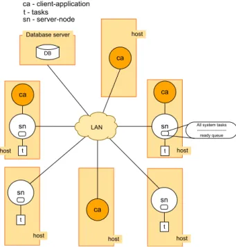
client-application This component represents a generic client-application, that is, it may be either a command-line client (e.g., Telnet) or Graphical User Interface (GUI) clients. Firstly, it should be able to request aserver-node(local or remote) to sched-ule the execution of a task. Secondly, it must be able to request the cancellation of a running task and also subscribe its interest in getting a given task’s progress. Moreover, it may also run in the same host (local) as theserver-node, as illustrated in Figure3.1, i.e., the cases where ca (client-application) andsn (server-node) are inside the same rectangle shape. Local means that the server and client are running in the same host, and remote in different hosts.
server-node This component is responsible for making scheduling decisions, such as task dispatching by communicating with other servers/schedulers. The selected node for executing a given task (t) launches the executable oftand opens a com-munication channel between both to monitor the evolution of thet’s execution. An-other responsibility of a server-node, is to report, to interested parties, the progress of the task currently in execution. It should be stated that a server-node may sup-port connections with multiple client-applications at the same time and it is not required to be connected with any client-application.
Database server This component stores the results generated by the execution of a task by a server-node. A result is a dataset generated by a task and it is identified by a database relation primary key.
task It represents the execution an automatic task of PLMI2 application. The PLMI2 tasks were, up to now, integral parts of PLMI2, and now for the purposes of this system they have to be independent applications. Therefore, when a task is start-ed/launched by aserver-nodethen it may read input datasets from theDatabase serverand should generate output datasets in this same database.
3. THEDISTRIBUTEDEXECUTIONPLATFORM 3.2. Overall Architecture
Figure 3.1: A general view of proposed system architecture.
The devised architecture comprises three distinct entities, i.e., the client-application, the server-node and the running task. In order for these to communicate, protocols have to be established.
Due to the lack of a centralized entity in the system architecture, it is in fact a dis-tributed protocol among server-nodes, and in order to meet this requirement it is nec-essary to have distributed algorithms for ensuring that all nodes will have a consistent view of the system’s state.
Therefore, all system components should agree on the protocols defined here, in such a way that each one of them can understand each other and cooperate to achieve the common goal, which is the execution all the scheduled tasks.
The communication among the system’s entities is achieved by exchanging messages and a message may contain several pieces of information. For instance, when a server-node receives a message from another server-server-node or from a client-application, then it triggers an appropriate action to process the received message and according to the kind of the message it makes some local decisions and may change its state, and additionally it may reply back to the message sender.
In the remainder of this chapter, we begin by explaining how tasks are uniquely iden-tified during their lifetimes and the content of a task, in Section3.3. In Section3.4to3.6
3. THEDISTRIBUTEDEXECUTIONPLATFORM 3.3. Task Identification and Contents
3.3
Task Identification and Contents
A task needs to be uniquely identified during its lifetime in the system. The best way we found to do this was by using the Universally Unique Identifier (UUID) specified by IETF RFC 4122 [53], which allows the generation of unique identifiers, across space and time, in distributed environments without a centralized coordinator.
A task has the following properties:
1. A Universally Unique Identifier (UUID);
2. The associated executable file name;
3. The number of input datasets required to be assigned for it to become aReadytask;
4. The identifier of the client-application’s host which ordered its execution;
5. A state, which may beSubmitted,Ready,Running,TerminatedorCancelled;
6. A priority, which can beloworinteractive. The priorityinteractiveis privileged over thelow;
7. A timestamp registering when it was submitted to the system;
8. The hostname of the server-node which scheduled it;
9. The hostname of the server-node where it is running, if its state equalsRunning;
10. The required identifiers of input datasets;
11. The identifiers of output datasets.
3.4
Communication: Client-application
↔
Server-node
In this section we describe the interaction protocol between a client-application and server-node, for each operation offered by the system to client-applications, i.e., the schedul-ing of a task, cancellation of a task execution and, subscription of interest in gettschedul-ing the progress and state of a task. For these three operations, the interaction follows a request reply-reply pattern that is always initiated by the client. Additionally, the server, period-ically sends the progress of the tasks over which the client has revealed its interest.
This communication protocol consists of seven kinds of messages, described in Table
3.3. In case of the SCHEDULE message, when a client-application requests the schedul-ing of task ty which has an inputithat depends on the nth output of a tasktx then it should send the argument
−a task_uuid_x nth_output_x
to inform the server-node how to assign the required identifier of output dataset (thenth
3. THEDISTRIBUTEDEXECUTIONPLATFORM 3.4. Communication: Client-application↔Server-node
Message Parameters Description
SCHEDULE task_exec_name priority [-p
path_to_raw_files] [-a task_uuid_1 nth_output_1] ... [-a task_uuid_n nth_output_n] [-x parameters_file]
Allows a client-application to request a server-node to schedule the execution of an automatic task.
SUBSCRIBE task_uuid_1 ... task_uuid_n Allows a client to subscribe its interest in getting the progress and state of a set of tasks.
CANCEL task_uuid Allows a client to request a server to cancel
the execution of a task.
SCHEDULED task_uuid A server-node notifies a client-application
that a given task was scheduled.
SUBSCRIBED task_uuid_1 ... task_uuid_n A server notifies a client that its subscrip-tion to a given set of tasks was registered successfully.
CANCELLED task_uuid A server notifies a client that a given task
was cancelled.
PROGRESS task_uuid
percent-age_of_work_performed state
A server sends the progress of a running task to all clients that subscribed this task.
ERROR message A server-node notifies a client-application
that its request was not successfully pro-cessed.
Table 3.3: Format of the messages exchanged between a client-application and server-node.
SCHEDULED task_uuid
SCHEDULE task_name priority [optional params]
client-application server-node
or ERROR msg
Figure 3.2: Schedule an automatic task (client-application↔server-node).
The options of the SCHEDULE message are:
−a Indicates one of arguments ofty. An argument is composed by the UUID of a tasktx on whichty depends on and thenthoutput oftx.
−x Indicates that a parameter file (an XML) was provided.
−p Indicates that a file system path or a location within the LAN containing the raw data files was provided.


![Figure 2.3: Distributed scheduling architectures. Adapted from Li et al. [36].](https://thumb-eu.123doks.com/thumbv2/123dok_br/16529961.736267/36.892.213.635.133.313/figure-distributed-scheduling-architectures-adapted-li-et-al.webp)
![Figure 2.4: Hierarchical scheduling architecture. Adapted from Li et al. [36].](https://thumb-eu.123doks.com/thumbv2/123dok_br/16529961.736267/37.892.288.650.135.325/figure-hierarchical-scheduling-architecture-adapted-li-et-al.webp)
![Figure 2.5: The pull model for resource discovery. Adapted from Li et al. [36].](https://thumb-eu.123doks.com/thumbv2/123dok_br/16529961.736267/38.892.305.537.133.302/figure-pull-model-resource-discovery-adapted-li-et.webp)
![Figure 2.7: The push-pull model for resource discovery. Adapted from Li et al. [36].](https://thumb-eu.123doks.com/thumbv2/123dok_br/16529961.736267/39.892.219.709.135.360/figure-push-pull-model-resource-discovery-adapted-li.webp)
![Figure 2.8: The architecture of PGS. Adapted from Cao et al. [37].](https://thumb-eu.123doks.com/thumbv2/123dok_br/16529961.736267/43.892.153.785.126.528/figure-architecture-pgs-adapted-cao-et-al.webp)