Dissertation
Master in Computer Engineering – Mobile Computing
Jumping AI for Unreal Engine
Gabriel Quaresma Moreira da Silva
Dissertation
Master in Computer Engineering – Mobile Computing
Jumping AI for Unreal Engine
Gabriel Quaresma Moreira da Silva
Masters dissertation performed under the supervision of Professor Gustavo Reis and Professor Carlos Grilo, from Escola de Tecnologia e Gestão do Instituto Politécnico de Leiria.
iii
Acknowledgments
The author would like to commend the teachers and supervisors, Gustavo Reis and Carlos Grilo, for their continual and swift guidance throughout this project.
The author would also like to thank V. Sreedharan for sharing the source code of the 3D pathfinding mechanism employed in the game Drunk On Nectar, for its flying creatures, with the Unreal Engine Community.
v
Prior Note
This work resulted in the publication of the following article:
G. Silva, G. Reis and C. Grilo, “Voxel Based Pathfinding with Jumping for Games,” in EPIA Conference on Artificial Intelligence, Springer, Cham, 2019, pp. 61-72.
vii
Abstract
Pathfinding plays a vital role in video games, whether in terms of gameplay mechanics or player immersion. Commonly used methods only allow the simplest types of movements like walking and running. Although seldom, other types of movement, like swimming and flying, are also considered. Even rarer are mechanisms that natively contemplate jumps without the need of extra intervention of game developers. Most games overlook these movements on Non Player Characters, decreasing the realism of the experience.
This dissertation discusses the limitations of Navigation Meshes when it comes to take jumps into consideration, while offering solutions to some of its problems. However, found solutions lack in automaticity, requiring high implementation times.
In the interest of improving upon this problem, a new solution using grid-based any-angle pathfinding is proposed. In this approach, each cell of this navigation grid constitutes a voxel that delimits a small 3D space and is expressed in a shape of a cube. Voxels discretize the game world and are explored by a search algorithm to achieve pathfinding with jumps. In this context, performance is critical and the paths should be optimal and efficient.
Results show that the voxel based solution can be successfully applied in game development and that it has relevant characteristics that could justify choosing this method over the navigation meshes alternatives for jumping.
Keywords: Pathfinding, Jumping AI, Path Planning on Grids, Voxel Based Worlds
ix
Table of Contents
Acknowledgments III Prior Note V Abstract VII Table of Contents IXList of Figures XII
List of Tables XV
Acronym List XVII
1. Introduction 1
1.1.Motivation 1
1.2.Goals 2
1.3.Document Structure 2
2. Pathfinding Methods and Related Work 5
2.1.Waypoints 6
2.2.Navigation Meshes 7
2.3.Regular Grids 9
2.4.Other Methods 10
3. Integration of Jumping Behaviour on NavMeshes 17
3.1.Navigation Links 17
3.1.1.Pathfollowing problems 19 3.1.2.Implemented corrections 20 3.2.Manipulating the Agent Step Height 21 3.2.1. Detecting jump scenarios 23 3.3. Jumping velocity adjustments to Pathfollowing 25
3.4. Path cost of jumping 26
4. Voxel based Pathfinding with Jumping 29
4.1.System Overview 29
4.2.Functionality Assumptions 31 4.3.Constructing the Voxel Grid 33 4.4.Request Input Preparation 34
x
4.6.Node Identification 37
4.7.Node Validation 39
4.8.Smoothing Process and Final Output 41
4.9.Pathfollowing 43
5. Proposed System Evaluation 45
5.1.Experiments Setup 45
5.2.Results and Evaluation 47
6. Conclusion 53
6.1.Future work 54
xii
List of Figures
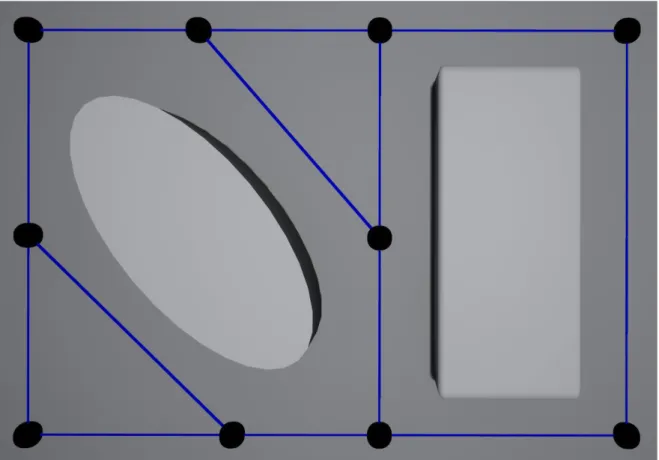
Figure 1: Waypoints navigation example. Nodes are represented by black spheres
and edges by blue lines. ... 6
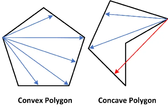
Figure 2: Comparison between convex and concave polygons for navigation. ... 7
Figure 3: NavMesh projections examples. Blue circles represent the real locations and red circles show the projected locations. ... 8
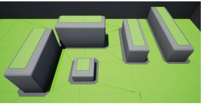
Figure 4: NavMesh example on UE4. The ground area is not connected to the areas on top of the obstacles. ... 8
Figure 5: Voxel grid example. Blocked voxels are represented by red cubes. For clarity, only voxels overlapping with obstacles are represented here. ... 9
Figure 6: Comparison between regular grids a. and visibility graphs b. ... 11
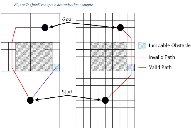
Figure 7: QuadTree space discretization example. ... 12
Figure 8: Jump limitations of Quadtree. when compared to regular grids. In this case, the purple path fails because the agent radius are taken into consideration for collision validation. ... 12
Figure 9: Probabilistic Roadmap path generation example 2D context. ... 13
Figure 10: Example of feedforward ANN architecture. ... 14
Figure 11: Navigation link on UE4. ... 18
Figure 12: Projection failure example when traversing a NavLink. In this case, the agent is too far away from any node in the NavMesh to successfully project its real location, represented by the blue circle. ... 19
Figure 13: Path recalculation problem example. In this case, the agent recalculates a path that traverses through the purple NavLink, causing it to return to the beginning of the NavLink instead of continuing. The agent’s projection on the NavMesh is represented by the blue circles. ... 20
Figure 14: Agent Step Height manipulation on UE4. a. Small Agent Step Height value; b. Big Agent Step Height value. ... 22
Figure 15: NavMesh height unreliability example. ... 23
Figure 16: Tracing for obstacles. A sphere trace is employed to look for jumpable obstacles while the line trace is employed for stairs and ramp detection. ... 25
xiii Figure 18: Stairs and ramp discretization example. The top of the voxels colliding
with the floor are represented by the blue squares. ... 31
Figure 19: Ground voxels identification. The underside/base of the ground voxels is represented by the blue squares. ... 33
Figure 20: Problematic projections examples. In these cases, the correct projected voxel of the yellow dot is not the voxel where it resides. ... 35
Figure 21: Capsule transformation to relative voxels positions examples. ... 35
Figure 22: Voxel expansion directions. The voxel to be expanded is represented by the black cube at the centre... 37
Figure 23: Voxel expansion density example. The white numbers located at the centre of each voxel represent the number of times that it was expanded during the search process to find a path between the purple and yellow voxel. ... 38
Figure 24: Jump linearity validation examples. ... 40
Figure 25: Smoothing operation example. The black path was smoothed into 3 segments that form the red path. ... 42
Figure 26: Ground segment optimization example. The black lines and dots represent the unoptimized path while the purple lines represent its correctly optimization. The red path is an invalid optimization because it steps outside of ground voxels. ... 43
Figure 27: Jumping when pathfollowing example. In the first jump, the agent can postpone the landing in C until D. However, this cannot be further extended, even if it realistically makes sense, because this process does not know if the space between D and E is safe for landing. ... 44
Figure 28: Analysed start and end pairs. The purple paths represent the solutions found with the default parameter values... 46
Figure 29: Game world employed for testing. ... 47
Figure 30: Length advantage of pathfinding with jumps. Jump actions are represented by the black spheres. ... 48
Figure 31: Example of a complex path including jumps. ... 48
Figure 32: Comparing different voxel sizes. ... 50
Figure 33: Comparing different validation strategies. ... 50
xv
List of Tables
Table 1: Inputs and outputs examples of ANN for navigation. ... 15 Table 2: Experiment paths characterization. ... 45 Table 3: Pathfinding results with the voxel based approach. ... 49
xvii
Acronym List
2D Two Dimensional 3D Three Dimensional A* A-star Algorithm AI Artificial Intelligence ANN Artificial Neural Networks NPC Non-Playable CharacterPC Personal Computer
1
1. Introduction
Pathfinding plays a vital role in video games, whether in terms of gameplay mechanics or player immersion. As a result, this subject has already been substantially researched, with many techniques and algorithms conceived to answer to this demand. However, there are still problems that were left unresolved, like the integration of jumping in pathfinding.
This dissertation discusses how existing pathfinding techniques can consider this behaviour, what are their limitations, possible improvements and proposes new integration solutions. Two navigation methods receive special focus: Navigation Meshes and Grid Navigation. Navigation Meshes, or NavMeshes, are the favoured method for pathfinding in recent 3D game developing and, therefore, this is where jump integration would be most beneficial. However, after investigating various strategies and assessing their limitations, the employed base pathfinding method for the proposed system was changed in favour of Navigation Grids. This discussion considers the NavMesh implementation present on Unreal Engine 4 (UE4), which employs the Recast algorithm [1] and the proposed solution uses voxel based any-angle pathfinding.
1.1. Motivation
Nowadays, most video games employ at least some aspect of pathfinding and pathfollowing. These are responsible for the navigation of the agents in the game world, be they Player or Non Player Characters (NPCs), and can heavily influence gameplay features as well as cinematic events. A lot of video games do not incorporate any jump behaviour for their agents because current methods do not offer an easy solution for it. These solutions require either a lot of handcrafting for marking/defining every jump that an agent could potentially make or are very limited in the jump scenarios that can be recognized automatically. As a result, it is common to see games that do not allow any kind of jumping, by players or NPCs, or games that only allow the players to jump. For example, games like The Elder Scrolls V: Skyrim and ARK: Survival Evolved only allow player characters to jump because they do not use the pathfinding system for this. That is done through player inputs. These choices can severely impact the game experience, either by decreasing or increasing the game’s difficulty or by affecting the sense of realism and immersion. For example, in a game where a NPC chases the player to kill him/her, it is
2 much easier to escape if the player can jump over walls but not the NPC. On the other hand, if nobody or only the player can jump, the game will feel less realistic because obstacles that the player feels instinctively that are easily crossed, like small rocks, have the same characteristics of an enormous wall, at least in terms of gameplay. These situations can severely break the immersion of players who, for example, see the NPCs taking an extremely long path to get around a small wall, instead of jumping over it.
With the increasing usage of NavMeshes and it becoming a standard in today’s game development industry [2], this limitation is more apparent than ever. Solutions have been developed, but it usually involves a lot of repetitive work on the game developers end. This situation is especially ungrateful for small development teams that do not have the necessary work force to implement these solutions, highly constraining the games they produce.
1.2. Goals
The main goal of this dissertation is to create or change the navigation algorithms present on UE4 to add automatic recognition of paths involving jumps while maintaining its currently ease and transparency of use and to analyse the obtained performance.
Existing pathfinding methods and techniques, with or without jump integration, are described and analysed, providing a state of the art for algorithms applied in navigation, be they for video games or robotics. Advantages and disadvantages for jump integration are also discussed for each of the presented methods, as well as current jumping solutions’ limitations.
Other objectives include: disclosing the investigation results publicly through the publication of a scientific article; sharing implemented solutions either by contributing to the UE4 itself or the Unreal Engine Community; allowing for path generation customization, providing options to increase path quality in detriment of performance and vice-versa; obtaining acceptable runtime performance for real time applications.
1.3. Document Structure
The rest of the document is structed as follows:
• Chapter 2 – Pathfinding Methods and Related Work – discusses existing pathfinding methods and their potential for jumping integration;
3 • Chapter 3 – Integration of Jumping Behaviour on NavMeshes – describes how
NavMeshes can be adapted to contemplate jumps;
• Chapter 4 – Voxel based Pathfinding with Jumping – describes the implementation of the proposed system;
• Chapter 5 – Proposed System Evaluation – reports the performed experiments and the obtained results;
5
2. Pathfinding Methods and Related
Work
Pathfinding is the ability to find a path between a given start and end locations. This is a simple task for a player to do but, for an AI, the problem can be very complex. The AI must know where it can move, how to avoid obstacles and how to find the shortest path possible.
For an AI to navigate through a game world with a continuous terrain, first, it needs to employ a space discretization technique. This way, it can build a representation of the world with all valid and invalid positions that it can occupy. Once this is done, search algorithms can be applied to calculate and determine the best path that the agent has to get to the goal. Most path finding algorithms use graph data structures to represent the world [3].
Space discretization can be an easy or difficult task depending on the game’s requirements and features. In turn-based games, it is a common practice to divide the world space into small square or hexagonal sections that form a 2D grid. This way, each cell is either free or occupied by an obstacle and the AI, can easily find the shortest sequence of valid movements from the start point to the goal. However, this solution usually only allows very simple movements for the agent: forward, back, right and left. Games that are looking for freer agent movements need to employ more complex techniques [4].
Nowadays, NavMeshes are the go-to method when developing a 3D real-time game that requires pathfinding capabilities. The usage of navigation grids in conjunction with a search algorithm is also popular in some games [5], working particularly well in game worlds that can easily be divided in small uniform areas.
On small and simple game worlds, a solution like manually placing waypoints where the agents can traverse might also be a good alternative with performance advantages. These methods were chosen for further discussion because of their widespread, simplicity and jumping integration capabilities.
6
2.1. Waypoints
A waypoint is a point/location on the game world where agents can be at. The waypoints method connects these points/nodes into a graph data structure to store and define navigable locations in a game world. Waypoints must be placed at locations reachable by the agent. Each waypoint is checked in order to verify if there are any obstacles between it and other nearby nodes. For each pair of nodes, if there are no obstacles, an edge is created. This way, an agent can safely move through the nodes and edges without fear of encountering any obstacles (see Figure 1). Theses nodes and edges form a data structure that can be used in conjunction with search algorithms to find the desired path. To integrate jumping behaviours, one would only have to place waypoints in the air locations where the agent is supposed to pass through. Other nodes on the ground would connect to these and form an edge that requires a jump to be traversed.
On the other hand, this system also significantly limits areas where the agent can move, resulting in unrealistic and strange behaviours [3]. This happens because agents are only allowed to move through edges, which are verified not to have any obstacles. Note that agents cannot traverse interior areas bounded by edges because these may have
7 obstacles and, therefore, are not safe for navigation. To counter this, it is possible to place more waypoints, increasing the areas where an agent can move. Although this allows more movement freedom and accuracy, it implies more development time and a significant performance decrease.
Usually, waypoints are manually placed in the game world by the level designer, causing this task to be very repetitive and time-consuming. Some degree of automation can be achieved in this method through the automatic generation of the edges between nodes. Nevertheless, it still demands a lot of effort.
2.2. Navigation Meshes
A navigation mesh is a graph data structure that contains the representation of the navigable areas in a game world. Using this, an AI agent knows where it can and cannot move, thereby assisting in the effort of pathfinding. This is, essentially, a representation of a game map composed of polygons (polygon meshes), similar to the game floor mesh, but simpler and invisible. Adjacent polygons are connected to each other through nodes, which the agent can traverse.
Only convex polygons constitute this mesh. This way, any two points on the polygon, be they at the boundaries or in the interior, can be connected with a straight line without passing outside of it. Regarding AI navigation, this means that an agent can, assuredly, move between the points inside an area in a straight line without any problems (see Figure 2).
8 With this representation, it is possible to move from point to point to cross an area or from node to node to move through different areas until a destination is reached. Untraversable areas do not have any nodes in them, being ignored by pathfinding operations. This way, a path is constituted by a sequence of convex polygon areas that the agent must traverse in order to reach the goal. These resemble the real navigable spaces, providing extra insight on the geometry of the map.
To use this data structure, agents must project their real world locations to the correspondent ones on the NavMesh (see Figure 3). Even if similar to the surface of the floor, NavMeshes have many differences and usually have different coordinates. If an agent is too far away from any point on the NavMesh, the projection will fail, and the agent is not able to engage in any pathfinding operations.
Figure 4: NavMesh example on UE4. The ground area is not connected to the areas on top of the obstacles. Figure 3: NavMesh projections examples. Blue circles represent the real locations and red circles show the projected locations.
9 Navigation meshes are usually constricted to walkable surfaces (see Figure 4) and, therefore, agents will only consider areas of the map that are directly connected by ground to their locations. This way, agents cannot climb walls to reach other areas, always requiring direct access through a stair case or a ramp. Since no aerial locations are considered, it is impossible to include jumps, however, it is possible to let agents step over obstacles. The UE4 implementation of NavMeshes and possible jumping solutions are discussed in Chapter 3.
2.3. Regular Grids
Just like a chess board is divided in little squares that form a grid, so can a game world be discretized into small cells (see Figure 5). Agents can use this grid to know where they are and how can they reach a certain goal. Given a defined start and destination cell, one can calculate the sequence of unblocked cells that make the path to the goal, effectively creating a path that the agent can follow.
Most games employ this method in a 2D context, where the agents can only move on two axes. However, this can also be used in a 3D context, in which cells are called voxels. These are usually expressed in a shape of a cube and it is possible to map a 3D space by arranging them in a 3D grid format. This way, each possible location on the grid is expressed by a voxel. As a bonus, the location of a voxel can be known through its relative position to other voxels. Grids are widely used to discretize terrain in video games and have several desirable properties. These provide simple data structures that can be easily Figure 5: Voxel grid example. Blocked voxels are represented by red cubes. For clarity, only voxels overlapping with obstacles are represented here.
10 integrated with many search algorithms and can quickly discretize the game world by overlapping and marking occupied cells as blocked. Pathfinding accuracy can be improved by increasing grid resolution, i.e. decreasing cell size [4].
In the context of path following, a voxel grid can be used to represent the navigable areas, like a NavMesh. Each voxel can either be valid or invalid depending on whether agents can or cannot move through it. Voxels can be considered invalid if they are occupied by an obstacle or for other reasons. For example, if the agent body occupies multiple voxels, then a voxel is valid only if the other voxels next to it, needed by the agent, are also valid. Once this data structure is built and the voxels are tested for validity, it is possible to apply a search algorithm to find a path between the agent and a goal position. This approach may have unrealistic restrictions when it comes to movement freedom, since the agent has to move through the centre of voxels, i.e. follow the grid connecting edges. Aside from this, the shortest path on the grid graph is probably not the shortest path in a continuous terrain [6]. However, these issues are not new and have been addressed by many solutions, some of which are described in [3], [4] and [6].
Unlike NavMeshes, this approach maps all the three-dimensional space, meaning that it accounts for different vertical positions of an agent. With NavMeshes, the location of an agent is always projected to the correspondent position on the NavMesh, ignoring, to an extent, the vertical coordinate. If an agent is 1 or 2 meters above the ground level, its projected location will be, most likely, close to the floor, while in the grids approach, its position will be the corresponded voxel that is on the air. This way, it is possible to consider other types of movement, like jumping, swimming and flying, because the vertical axis can be correctly known and mapped in the navigation data structure. For example, the game Drunk on Nectar uses a pathfinding system based on this approach for its flying creatures [7].
2.4. Other Methods
Many other methods and discretization techniques still exist, some of which are described in [8]. However, these are less appealing options for jump integration due to their characteristics, having worse runtime performance or their complexity hindering the validation and identification of possible jumps.
11
Visibility Graphs are employed to discover the shortest path that does not collide
with any obstacles in a Euclidean world and are widely used in Robotics [9]. The nodes of these graphs are constituted by the vertices of the obstacles and the start and end locations of a pathfinding request. Nodes connect to each other through linear edges if there are no obstacles in between (see Figure 6b). Graphs can be automatically constructed for the game world and can be explored through common search algorithms to find paths. Unlike regular grids and NavMeshes, this technique has the advantage of guaranteeing that the length of found paths is always as short as possible in a Euclidian world, as long as the search algorithm is optimal. This results in more realistic pathfollowing behaviours, reducing sharp turns to a minimum (see Figure 6b). However, this method has generally high runtimes [4] and is mainly used in 2D settings. It is possible to extend this to 3D spaces, as seen in [10], but this is already a complex solution that would be over encumbered by jump integration.
Quadtree is a variant of regular square grids that groups adjacent cells into bigger
areas to improve efficiency in pathfinding requests [8]. The construction process starts with a low-resolution grid, i.e. big cell size, and repeatedly divides each obstructed cell into four smaller ones until these reach the smallest acceptable size (see Figure 7). This way, search algorithms can explore less nodes to find a path. Its main advantage is the increase in performance, which is essential for some applications, like multiagent pathfinding. However, bigger cells further constrain movement freedom and, therefore, the path quality decreases, resulting in bigger generated paths. This aspect also makes jump
Figure 6: Comparison between regular grids a. and visibility graphs b.
12 identification more difficult, reducing the number of possible jumps found by the system (see Figure 8).
Probabilistic Roadmaps are commonly used in Robotics to perform motion planning
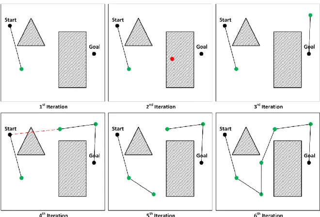
operations. This method is similar to the waypoints approach, however, nodes and edges are automatically generated and it can support any degrees of movement states, for example, 3D location and rotation. It has two stages: the learning stage, where the graph is built, and the query stage, where paths are calculated [11]. This sampling-based technique randomly choses points in the solution space to be nodes. Nodes colliding with obstacles are discarded. Once a new node is created, edges are built to other near nodes, as long as these do not collide with obstacles (see Figure 9). The graph can be checked every iteration
Figure 7: QuadTree space discretization example.
Figure 8: Jump limitations of Quadtree. when compared to regular grids. In this case, the purple path fails because the agent radius is taken into consideration for collision validation.
13 to discover a possible path and the system can wait until more samples are collected to improve path lengths. This process can be improved in certain situations by guiding the search, for example, every so often picking points near the start and end location. This technique is particularly useful when agents have many degrees of movement states, like jumping motions, which produces an immense number of nodes in a regular grid discretization technique. However, given the uncertainty associated with this method, path quality can greatly decrease either by generating paths with bigger lengths or by missing valid paths, resulting in unrealistic behaviours. These downsides can be improved at the cost of runtime performance, but this is also essential to pathfinding in games.
14
Machine learning can also be employed for navigation, such as the case of Artificial Neural Networks (ANN). ANNs are information-processing systems inspired by the central
nervous system of animals. Artificial neurons process the input data, delivering the output data, which can be used to perform tasks. Feedforward ANNs are the most common employed type and have the best data-processing speed [12], which is essential in pathfinding. These have an architecture composed of several layers of artificial neurons, where there is always an input layer, which receives the input data, an output layer, which delivers the output data, and where it can exist one or more hidden layers. Each artificial neuron, except for the ones in the output layer, is connected to all neurons in the next layer and each of these links has an associated weight (see Figure 10), represented by a real number. Modifying these weights affects the output data and learning is done through the adjustment of these values. In a navigation context, one of the most straightforward training approaches is to use a genetic algorithm [12]. This way, it is possible to optimize the ANN to better perform the pathfinding tasks.
Table 1 presents a possible set of inputs and outputs of a navigation system. In this example, agents chose the next movement direction based on the current and goal locations and how much free space they have in four directions. To navigate through the world, agents execute the ANN in a loop until they reach the goal. To train this ANN, random solutions, i.e. weight value sets, are executed several times in different scenarios and a score is calculated based on their performance in the different simulations. In an iterative way, the genetic algorithm stochastically chooses the best solutions through a process inspired by natural selection, as it happens on nature. Variation operators are applied to
15 selected individuals to create different solutions from the current ones, potentially better. After a set number of iterations, the best solution is returned.
Table 1: Inputs and outputs examples of ANN for navigation.
Inputs
Outputs
Current X Position
Next Move Direction X Current Y Position
Goal X Position Goal Y Position Right free distance
Next Move Direction Y Left free distance
Forward free distance Backwards free distance
This last approach is particularly good for real-time dynamic environments, where obstacles are frequently moved, created and destroyed [12], and requires less CPU resources than other approaches. However, correctly training an ANN can take much time and agent behaviours can be unpredictable and unrealistic [13], given that, in most cases it learns without human interference. Implementation time is a crucial aspect in game development and, as a result, machine learning is rarely employed nowadays for pathfinding.
17
3. Integration of Jumping Behaviour on
NavMeshes
NavMeshes represent the navigable areas of the environment. However, this data structure holds no information about areas in the air, meaning that if, for example, two surfaces are separated by a pit, it is the same as if they are separated by a wall. In these cases, no nodes will be present between these areas and, therefore, these will not be considered when calculating a path. Regarding jumping behaviours, this is the most disadvantageous aspect of NavMeshes and might be a reason for choosing another approach that does not suffer from this, like Regular Grids. However, even if difficult, it is still possible to build paths that use jumps with NavMeshes. This chapter focusses on the two most straightforward and efficient solutions for jump integration, describing their principal limitations. More complex solutions have been developed by other authors, but these also tend to suffer from significant drawbacks, like the ones described in [14], [15], which only consider jumps when the agent reaches a dead end.
3.1. Navigation Links
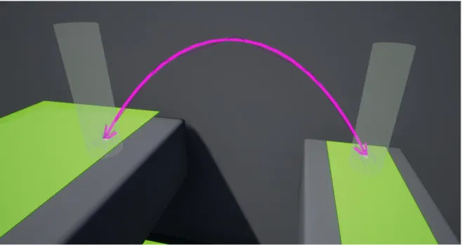
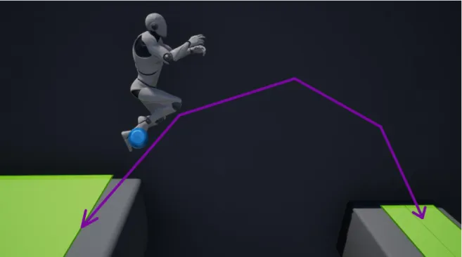
UE4 has implemented NavLinkProxys, objects that allow level designers to manually connect a node from one area to a node of another on a NavMesh (see Figure 11). The Unity game engine also employs NavMesh links to perform an equivalent functionality. Through these links, agents know that they can navigate directly between those points, for example, they might know that it is possible to fall down from a platform to land on another. These links only define that there is a valid path between the nodes. However, following it might require extra actions like jumping, which the developer must accommodate in the pathfollowing process.
18 In the solution proposed by Mieszko Zielinski, the main developer of the UE4 navigation system, in [16], the agent acquires jumping behaviours through the marking and recognition of jump areas. In this case, jump areas are composed by two nodes connected through a NavLinkProxy. An agent can detect when it entered one of these areas and change its behaviour accordingly, by jumping, if necessary.
The usage of NavLinks does not increase the nodes of a NavMesh, it only connects two of them. This way, it is assumed that an agent can travel between them, just like any others. The two connected nodes can be far away from each other and the space between them will have no in-between nodes. However, when traversing through these segments, it is likely that the agent wrongly projects its location, potentially resulting in complications, like not knowing where it is on the NavMesh (see Figure 12) and failing ensuing pathfinding requests.
There are mechanisms that automatic detect jump scenarios and place NavLinks, e.g. [17]. However, these are very limited, leaving developers to manually place all or most links. This is a very repetitive task and may require a lot of manual work, just like creating a NavMesh manually, which makes this not a very good solution in the long run.
19
3.1.1.
Pathfollowing problems
When an agent is ordered to move to a certain location, the navigation system must calculate a path to begin the pathfollowing process. Once the path is defined, the agent can use it to traverse the world. A path can involve a NavLink and it will be valid even if the agent must step outside of the NavMesh to traverse it. The system has no information regarding that and, to it, it is like any other connected point. Stepping outside of the NavMesh means that the agent cannot calculate any new paths, but it does not affect its ability to follow one. As a result, the success of this operation depends only on it knowing how to correctly traverse between the two points connected by the NavLink. This happens because the path is only calculated once before the pathfollowing process, meaning it does not need to project the agent position during the actual navigation.
There are several situations that might trigger a path recalculation during the traversing of a NavLink, for example, if the destination changes. If the agent receives an order to stop when traversing a NavLink, it will also originate problems. If any of these cases happens, then the agent stops and can be unable to move ever again, because it cannot project its location. Most of these cases are undesired and cause this solution to be less effective.
Figure 12: Projection failure example when traversing a NavLink. In this case, the agent is too far away from any node in the NavMesh to successfully project its real location, represented by the blue circle.
20 Recalculating a path during the traversing of a NavLink which crosses untraversable areas does not always causes the agent to get stuck outside of the NavMesh. Location projection commonly uses tolerance intervals in the world axes. This way, the projected position corresponds to the closest point on NavMesh to the agent’s feet, as long as this is within the interval. It is assumed that projected positions correctly represent the real locations and that differences can be ignored when navigating the agent. As a result, if an agent is traversing a NavLink when it is ordered to move to a new target and the projection succeeds, then it ignores its previous action and tries to move in a straight line to the first point in the new path. If this path happens to include the same NavLink, then the agent returns to the beginning of the NavLink to traverse it again (see Figure 13). In this scenario, recalculating a path that involve the same NavLink, always makes the agent return to its beginning, meaning that if the system is constantly repathing, the agent is not able to traverse the NavLink. This is not an issue to the automatically connected nodes and represents an undesired behaviour.
3.1.2.
Implemented corrections
This solution suffers from a few flaws that reduce its interest to game developers. The repeatability of the work needed for its implementation is the biggest drawback, but not the only one. It is impossible to easily solve the first problem, however, that is not the case of some of the undesired behaviours mention in the section above.
If analysed, it is apparent that these cases are caused by interruptions to the pathfollowing process during the traversing of NavLinks. The UE4 pathfollowing system allows an agent to stop when traversing a NavLink segment. When this happens, it may Figure 13: Path recalculation problem example. In this case, the agent recalculates a path that traverses through the purple NavLink, causing it to return to the beginning of the NavLink instead of continuing. The agent’s projection on the NavMesh is represented by the blue circles.
21 result in a good outcome, where the agent stops normally and can still move if ordered, but, in most cases, this results in a bad outcome. Generally, traversing a NavLink implies that the agent performs additional actions other than walking, like falling, jumping and landing. Cancelling the path following will also cancel these actions, originating problems. For example, if a character stops moving during a jump, it might not land in the correct spot and fall down a ledge. Usually this is not the desired behaviour; the agent should finish landing and then stop. This way, it is guaranteed that it will not end up outside of the NavMesh.
Implementing the restriction that agents should always finish traversing a NavLink before doing anything else fixes these problems. In this solution, the path interruption problem is solved because the agent always arrives at the end of a NavLink before doing any other actions, not stopping during one, even if ordered. The path recalculation problem is solved in the same way, because the agent first finishes traversing the NavLink instead of constantly returning to its beginning. It usually makes sense for an agent to conclude navigating a NavLink segment even if it is not currently outside of the NavMesh, therefore this alteration does not cause unrealistic behaviours.
3.2. Manipulating the Agent Step Height
A NavMesh can be generated manually or automatically. The second method is the most popular because it requires considerably less implementation time. UE4 uses an automatic process and allows customization of the generation process through the usage of some parameters. A NavMesh is a simplification of the traversable areas in game map, employing several methods to reduce the work required to generate and use them. The degree of simplification can be manipulated, originating very precise NavMeshes, which are expensive to generate and use, or very simple and inexpensive ones, that have worse results.
Aside from this customization, each NavMesh must know some information about the agent that will be using it. In UE4, the most important parameters associated with an agent for NavMesh generation are: Agent Height, Agent Radius and Agent Step Height. However, for this solution, we only focus on the last parameter.
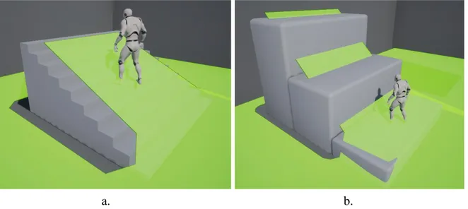
22 The Agent Step Height parameter of NavMeshes determines the maximum height differential between two connected points on a terrain that the agent can traverse by walking. For example, it determines the maximum height of a stairs step that the agent can climb. By increasing this parameter, we are defining that agents can climb bigger steps. This way, the pathfinding system assumes that an agent can step over obstacles if their height is smaller or equal to the Agent Step Height value. As a result, new paths can be found (see Figure 14), however, the ability of the agent to traverse these is dependent of the pathfollowing system.
By increasing this value, the NavMesh covers a lot more areas of the environment. The pathfinding process acts accordingly to these new areas and paths will feature areas where the agent cannot walk on. As a result, when following these paths, the agent might get stuck at walls, because there is no information on where to jump or land. It is possible to detect these situations and prompt a jump action, so it can continue with the path, but this has to be done separately from the NavMesh. For example, when an agent detects a wall that is along the path and ahead of it, then it jumps. However, not every obstacle requires a jump to traverse it, the agent may be capable of walking over it or, sometimes, simply falling is sufficient.
However, even if it is possible to support jump actions through NavMeshes, these are very limited and do not cover a lot of the jump cases. The agent will only jump from one platform to another if these are directly connected by the NavMesh. This only happens if the distance between them is very small, i.e., not enough for the agent to fall through, and Figure 14: Agent Step Height manipulation on UE4. a. Small Agent Step Height value; b. Big Agent Step Height value.
23 if the height difference between them is not larger than the Agent Step Height value. Agents cannot jump between separated platforms because the corresponding areas in the NavMesh are not connected. Considering that the platforms are connected, then agents can walk or fall to move between them. However, the distance agents can jump down is always the same as the distance that they can jump up, severely reducing the usage cases that involve falling.
This solution can be combined with the NavLinks, covering the cases that it cannot solve. This reduces a lot of work for the game developers, but still suffers from the time-consuming aspect of the NavLinks, even if minimized.
3.2.1.
Detecting jump scenarios
Figuring out when a character should jump can be a complex and demanding task, impacting the performance of the game. A level designer could manually mark the areas where the agent would need to jump, but this suffers from the same problem of the NavLink method, it is a time-consuming task. A better approach would be for the agent to automatically detect jump scenarios.
NavMesh Height
The points of the NavMesh are simplifications and are almost always not in the exact position where the terrain is. If an agent moves from one point on the NavMesh to another that is more elevated, it usually means that the agent vertical position has increased, but not always. For example, the NavMesh nodes mapping a street and its sidewalks can have no height differences between them, even if the sidewalks are more elevated. This happens because of this simplification phenomenon.
24 When manipulating the Agent Step Height parameter to serve as the jump height, these simplifications became much more erratic and unreliable. The points in the NavMesh can indicate that the agent is walking down or up a pathway, when, in reality, the floor of the path is completely flat (see Figure 15). Because of these common errors in the position of the NavMesh, it is not advisable to detect the necessity of jumping through it.
Jumpable Obstacles
Detecting when the agent collides with a wall, and triggering a jump then, might be a good solution in some cases. However, by triggering jumps this way, the fluidity of the movement and pathfollowing speed of the agent could be significantly limited. In this solution, the jump detection is done by sphere traces. Projecting spheres straight in front of the agent lets it know if something that he cannot walk over is ahead of it (see Figure 16).
However, just checking if there is an obstacle a meter in front of the agent does not solve all problems and can lead to undesired behaviours in some cases. Tracing for obstacles should only be done in the locations included in the path to follow. For example, if the agent is walking next to a wall and it comes too close to it, the wall might be detected as an obstacle and, therefore, the agent jumps, even if it is not required at all. In this situation, tracing for obstacles should be precisely limited to areas involved in the path, meaning that it should never collide with the wall, because the path consists of walking next to it, not over it.
Stairs and ramps
The agent might be capable of walking over some obstacles, just like a person can walk up a stairs case or a ramp. First, for a jump to be triggered, an obstacle would have to be detected at a height superior to the untampered Agent Step Height, not the one manipulated to generate the NavMesh that allows jumps. If the obstacle is below this limit, it means that the agent can walk over it and a jump is not required. If an obstacle is detected above this limit a jump might be required, depending if there is something below the obstacle that would elevate the agent’s position, like a ramp or step. The detection of steps or ramp is done by tracing an additional line, at the real Agent Step Height limit (see Figure 16). Depending on the terrain of the map, this mechanism may need to perform simple or complex validations. For example, small irregularities on the floor could be mistaken for a step, preventing a jump until the agent collides with the wall.
25
Problematic aspects of this solution
A few undesired behaviours surge by only dealing with obstacles directly in front of the agent. The agent’s movement is not always ideal, affecting the fluidity and speed of the agent. For example, in a situation of an agent falling into a small pit just to jump out of it in the next moment, the better solution would be to just jump over the pit. However, solving this problem would require a more complex jump detection system that would ultimately greatly decrease performance.
3.3. Jumping velocity adjustments to
Pathfollowing
For both solutions to work (Navlinks and the Agent Step Height parameter), the agent must have control over the movement when it is on the air, or at least, of the velocity applied when jumping. By default, the UE4 pathfollowing system considers that an agent should not move when in the air, meaning that it simply keeps the momentum and falls accordingly to the gravity. Agents cannot even rotate when falling, to face the path. This difference in the level of control when compared to walking can lead to some problems. When an agent jumps, the momentum can greatly impact the jumping trajectory, making the character land on the wrong spot, outside of the calculated path. This spot can be outside of the NavMesh, meaning that the agent cannot find any new paths. Even if the Figure 16: Tracing for obstacles. A sphere trace is employed to look for jumpable obstacles while the line trace is employed for stairs and ramp detection.
Line Tracing
Sphere Tracing
26 agent can recover from these cases or if it misses the right spot but lands on a valid position, this constitutes an unwanted behaviour. This aspect leads to erratic movements, bigger pathfollowing times and, in some cases, can make it so a path is impossible to traverse.
Movement control during fall
To solve this problem, agents were given control of its movements when falling. This way, it would be possible for them to compensate momentum and navigate to the correct landing point. However, too much control would be as if it is temporary flying, which might by unwanted. Moving on the air is significantly different from moving on the ground. The ground friction will help the agent to rapidly change directions, but on the air, this takes much more time. Even if the agent as the same level of control in these two situations, i.e. it can apply the same range of forces, the movement on the air still has problems when coming to a stop and when making sharp turns. This can affect pathfollowing, possibly reducing the efficiency of it or even getting the agent outside of the NavMesh.
Momentum cancelation
Another implemented solution is to reduce the undesired momentum during or right before a jump, i.e. reduce the velocity to all directions other than the direction of the path. This greatly improves landing accuracy. However, falling of an edge must be also taken in consideration, reducing or eliminating the unwanted momentum of an agent before it falls off any platform.
If the agent cannot change its velocity while on the air, that means that it must have exactly the right momentum force to complete the jump before the actual jump. Everything must be perfect before the jump, so it succeeds. Achieving this, is not a simple task and a lot of validations must be made. This way, the implemented system employs both of the discussed approaches to produce reliable results, even if sometimes the movements can be a bit unrealistic. For some games, agents moving when falling is an intended game mechanic and, for these games, this is not an issue.
3.4. Path cost of jumping
UE4 provides a method to make certain areas of the NavMesh costlier than others, meaning that the agents will tend to avoid these if a path that passes through the others
27 exists. However, in this solution, a jump itself does not reflect any cost for the path. Because of this, agents always chose the smallest path even if it requires a lot of jumps and takes more time to traverse it. If an agent is to avoid jumping, to a certain extent, and this solution is being employed, the developers would have to manually mark every jumping area with a higher path cost, greatly reducing the time efficiency of this solution.
29
4. Voxel based Pathfinding with Jumping
This chapter describes the implementation of an alternative pathfinding with jumping. The main goal of this research was to implement a navigation system as proof of concept that it is possible to perform pathfinding operations that support typical jump behaviours in an easy and transparent way that does not require any type of manual markings in the game world. For this purpose, the discretization technique chosen was a voxel grid. This way, it is possible to map ground and air locations into a navigation graph. This system is implemented in the UE4 and follows the structure and design principles of the built-in classes and pathfinding functionalities. It smoothly integrates the already existing pathfinding and pathfollowing components and allows developers to easily switch between approaches just by calling a different method. This way, agents are not restricted to just one pathfinding mechanism and can even employ different ones at the same time. For example, the same agent can use this system for jumping environments while employing NavMeshes for traditional navigation situations based on the resulting paths that each approach produced.
4.1. System Overview
The voxel pathfinding system must be able to navigate an agent in a game world. To do this, agents make pathfinding requests according to their characteristics. Requests are divided in three sequential phases: request preparation, path calculation and pathfollowing (see Figure 17).
To handle pathfinding requests, the system must validate and prepare the input of each request. It is necessary to project the start and end locations, i.e. convert the real world location to the correspondent cell in the grid, and build an agent collision profile employed for later validations. Once these tasks are done, the search process may start.
The search is the most complicated and time-consuming operation of this system. This includes calculating the best path, while validating it according to the request collision profile, jump capabilities and imposed jump moment restrictions. To perform this, a variant of the A* algorithm is used to explore the solution space, calculate the shortest path possible and return it in the format of a list of locations on the grid.
30 During the Path Calculation phase, and after the voxel grid search, the resulting path is submitted to a smoothing process that seeks to shorten it, making it more appropriate for continuous spaces, i.e. allowing any-angle movements. To finalize, each location is marked with tags that provide relevant pathfollowing information. These tags hold information whether the location is on air or ground and if it is a jumping, landing or land then jump point; some paths may require for an agent to land and then jump on the same location. At this stage, the final path is ready to be delivered to the pathfollowing process. This makes use of the locations and associated tags to correctly traverse the path while controlling the agent. To conclude, the system reports if the agent successfully reached the end location.
Our system was implemented with the usage of a grid that discretizes the game world into cells/voxels. Built paths may include locations in the air, without the need to do any kind of manual work. Agents can choose paths, which may, under extra validations, include jumps that the agent can perform.
31
4.2. Functionality Assumptions
A pathfinding system complexity and features can greatly differ between games. For example, pathfinding for an agent that is simulating a shark behaviour, always moving in a circular pattern, significantly differs from the traditional methods [19]. As a result, it is common practice to adapt and specialize these mechanisms to better integrate each game. Given that this system is designed for general use and to better focus on the main goal/functionality of this system, it was necessary to establish limits to its functionalities.
This approach does not consider methods where agents elevate themselves on the grid other than jumping. As result, stairs and ramps that the agent could walk on are treated as if it had to jump to traverse them. These cases usually are not properly discretized by the voxel grid (see Figure 18) and can increase the difficulty of jump identification and validation. This happens because the floor altitude can greatly change inside the same voxel, thus requiring the system to calculate the exact distance to the floor instead of using the location of the voxel. Aside from its difficulty, it is possible to implement this behaviour, however this can greatly impact the time necessary to construct the voxel grid.
As a first approach, our system only considers linear jumps, i.e. jumps that maintain the same movement direction until the end. Some games already impose this limitation on
Figure 18: Stairs and ramp discretization example. The top of the voxels colliding with the floor are represented by the blue squares.
32 its agents while others may allow for agents to steer themselves while on air. It is possible to adjust this approach to expand on the jump direction freedom, but it will ultimately decrease the performance of the system and it requires the usage of a more complex pathfollowing system. Linear jump identification and validation is already a heavy and demanding task, the addition of yet more jump cases would greatly impact runtimes and, therefore, is not a priority.
It is assumed that agent’s shape is or can be simplified into a capsule. Aside from knowing that a voxel is blocked or unblocked, this system may perform in game collision detections to validate paths. In these cases, it employs a capsule shape to represent the agent. Given that in game development it is standard to simplify object collision shapes to improve performance, this restriction should not significantly impact the number of games that can use the system. For example, in UE4, humanoid characters display complex shapes with countless edges, but for collision detection these are normally simplified into a capsule that involves it. UE4 also has this assumption in its built-in navigation system, only letting agents specify their radius and height.
The agent’s momentum can greatly impact the jumping trajectory, for example, making the agent land on the wrong spot, outside of the calculated path and, as a result, failing to follow the path (see Section 3.3). In order to avoid these situations, either the pathfinding system has to consider the agent’s momentum or the pathfollowing system must later adjust where it would compromise the pathfollowing process. It is not unusual for games to disregard this aspect in favour of improving the game experience. Some games completely negate the controlled character’s momentum right before a jump or let that the players control the agent’s momentum, effectively changing its speed and movement direction while on the air, like in the game Divinity 2: The Dragon Knight Saga. Seeing that games tend not to choose the most realistic approach, this system does not take the momentum into consideration and, therefore, the pathfollowing counterpart must be able to change the agent’s velocity when jumping so that it successfully reaches the landing location. Like the previous solutions, this approach requires that the currently implemented pathfollowing system on UE4 is adapted. These adjustments are identical for all presented approaches and are discussed in the Section 3.3.
33
4.3. Constructing the Voxel Grid
Before being able to handle requests, some verifications must be performed on the voxels. These can be done by analysing all the voxels on the grid, before any request takes place, or just when necessary. i.e. lazy loading. This system follows the first approach in order to improve request performance.
Once the voxel grid is created and placed in the world, each voxel is verified if it is overlapping any geometry of the map. In this case, any obstruction in a voxel is sufficient to mark it as blocked, i.e., unblocked voxels are composed entirely by empty space.
Unblocked voxels that have a blocked voxel directly below them, are considered as ground (see Figure 19), while all the remaining unblocked voxels are considered as air. This distinction is essential for the path validation process, which employs different validations methods for each type of voxel.
In the interest of improving performance, the system caches the valid directly adjacent neighbours of each voxel after the grid is constructed. This way, the search algorithm performs less validations and quickly accesses adjacent voxels. A neighbour is valid if a line from the centre of the current voxel to the centre of the neighbour voxel does Figure 19: Ground voxels identification. The underside/base of the ground voxels is represented by the blue squares.
34 not overlap with any blocked voxels. An option also enables this process to employ a lazy loading approach to only cache neighbours of voxel when it is accessed for the first time by a pathfinding request.
Mapping the game world into a voxel grid has problematic aspects, some of which can greatly impact results depending on the game world geometry and grid properties. When employing this discretization process, it is encouraged to align the grid with the map in the best possible way, i.e., in a manner that increases the number of unblocked cells (see Figure 19). This is a crucial step that can greatly increase accuracy. However, this task is usually manually performed by developers, which, depending on the map design, could take significant adjustments. In the interest of facilitating this process, game worlds should be created with the alignment and size of voxels in mind.
Voxel size can also severely impact pathfinding tasks, for example, smaller voxels increase accuracy, but greatly decrease performance. The optimal voxel size will most likely differ from each game and it should be carefully deliberated and tested. Usually, it is best to have the voxel size equal to the size of the agents that employ this system, striking a balance between accuracy and performance. If the agents in question do not have a cubic shape, like the voxels, it is best to set the voxel edge length equal to its width. The size of voxels should be always connected to the size of the agents. For example, if agents are much smaller than the voxels, their movements will become unrealistic constrained, making extremely wide turns and possibly not finding paths through openings where it could easily fit.
4.4. Request Input Preparation
In order to start the search process, it is necessary to validate and prepare the input of each request. To begin, the system must try to project the start, usually the agent’s feet, and end locations to the navigation data structure, converting, if possible, a real world location in the correspondent voxel on the grid. Sometimes, positions that appear valid in the real world correspond to invalid voxels on the grid. In these cases, it is necessary to find the best representative valid voxel of that location (see Figure 20). Usually it is either the next valid voxel above the initial projection or the closest valid voxel to it. In the proposed system, both methods are employed and configurable and the second one is used if the first fails.
35 Each request is affiliated with an agent and its body size can impact the pathfinding results, for example, a big agent is not capable of passing through a small gap. In this system, each request comes with the height and radius of the agent since the collision detections consider the agent to be represented by a capsule. From these measurements, the system must construct a voxel collision profile, i.e., transform the capsule representation into a list of relative voxels positions that the agent occupies when positioned in the centre Figure 20: Problematic projections examples. In these cases, the correct projected voxel of the yellow dot is not the voxel where it resides.
36 voxel (see Figure 21). These profiles are later used in the search process to determine if the agent can stand on a given voxel without its body occupying any blocked voxels.
4.5. Search Algorithm
Once all the voxels are marked either blocked or unblocked and ground or air, the system is ready to handle pathfinding requests. To handle such requests, the pathfinding system must know the corresponding start and end voxels, the agent jump capabilities and the agent collision profile.
The search process is accomplished using the A* algorithm [20]. This is a commonly used heuristic graph search algorithm that sorts nodes according to the value returned by the evaluation function
f (n) = g (n) + h (n),
where each node n represents a combination of a voxel and the movement state that lead there, g(n) corresponds to the minimum cost between the start node and n and h(n) corresponds to the estimated cost between n and the end node [21]. The algorithm selects to expand the next node with the smaller f(n) value. Once a node is expanded, its neighbour nodes are added to the frontier list of nodes, sorted by the result of the evaluation function. As proven in [20], if the heuristic function h is admissible, then the result will always correspond to the shortest path on the grid. An admissible heuristic never overestimates the real shortest path cost to the goal.
To begin this process, the starting node is analysed. If this does not correspond to the end voxel, then it is expanded (i.e. nodes will be created for all adjacent voxels). Adjacent voxels are then validated and added to the frontier, only if these never were on it or if g(n) is smaller than the previous cost of the same node. After adding nodes to the frontier, the first node is dequeued and analysed as already described. This cycle continues until either the frontier is empty (meaning that there is no valid path) or a node corresponding to the goal is reached.
37 In the interest of improving the length of the resulting paths, this system allows for voxels to be expanded in 26 directions, 6 straight and 20 diagonal directions from its centres (see Figure 22). The cost g(n) is exactly the shortest sum of distances between sequence of voxels that connect the start node to n. This way, nodes connected diagonally are picked over other ones, reducing the path’s length.
The simplest and most used way to guarantee that the heuristic is admissible is by employing the Euclidean distance between nodes, which is always the shortest possible path cost between two points in a Euclidean world. The closer the heuristic value is to the real best possible cost, the less nodes are expanded and, therefore, the better the performance [21]. So, in this system, h(n) is set to the minimum length of the path that complies with the allowed movements on the grid. This path uses primely diagonal movements on the grid, only resorting to straight movement if required.
4.6. Node Identification
Nodes employed in the search process are composed of different properties according to their type. Both types, ground and air, have a correspondent voxel, but air nodes have two additional properties: voxel where the jump started and jump direction. As a result, ground nodes corresponding to the same voxel are always equal. However, air nodes corresponding to the same voxel can be different from each other. The extra properties are necessary because movements in the air are much more restricted. An agent