UNIVERSIDADE DA BEIRA INTERIOR
Engenharia
Philosophy and Ethics of
Aerospace Engineering
António Luis Martins Mendes
Tese para obtenção do Grau de Doutor em
Aeronautical Engineering
(3º ciclo de estudos)
Orientador: Prof. Doutor Jorge Manuel Martins Barata
Dedicatória
Gostaria de dedicar esta tese a minha Avó Rosa e aos meus Pais por acreditarem em mim e pelo apoio estes anos todos desde a primeira classe até agora.
iii
My deepest gratitude to Professor Jorge Barata for the continuous support throughout college since I was invited to become a member of his Research and Development team until the present days. His patience, motivation, knowledge, individual and family values have been a mark on my own professional and personal life. His teaching and guidance allowed me to succeed in life to extents I never thought it could have happened. I could have not imagined having a better advisor and mentor for my PhD study.
Beside my mentor, I would like to say thank you to Professor André Silva and my colleague and friend Fernando Neves for all the good and bad moments throughout college and life events.
I would like to recognize some other professors that made a difference in my studies and career paths – Professor Koumana Bousson, Professor Jorge Silva, Professor Pedro Gamboa, Professor Miguel Silvestre, Professor Aomar Abdesselam, Professor Sarychev and my colleague Maria Baltazar.
Last but not least, I would like to thank my family: my wife Kristie, my kids (AJ and Bela) and my neighbor Fred LaCount for the spiritual support throughout this study and phase of my life.
António Luis Martins Mendes Covilhã, UBI and Golden, CSM - July 2016
v
A Engenharia é uma atividade humana reconhecida num determinado período da história (séculos XVII e XVIII), quando alguns militares projetaram, construíram, operaram e mantiveram fortificações e máquinas de guerra e, em seguida, essas atividades foram transferidas para aplicações não militares. A Engenharia continuou a mudar geográfica e socialmente e atualmente tem uma abrangência extremamente ampla e a sua relevância não é apenas baseada em tecnologia. No entanto, o seu papel na tecnologia é decisivo, pois é em grande parte pela tecnologia que a sociedade atual mantém sua coerência. A Filosofia da Tecnologia tem estado particularmente atenta ao impacto da tecnologia na sociedade e na cultura, mas não na própria tecnologia. Na verdade, a Filosofia não deu uma atenção adequada à engenharia. Pelo contrário, ao menos desde a década de 1960, membros da comunidade filosófica têm acusado os engenheiros de poluir o mundo natural, transformando o clima, fazendo produtos de consumo inúteis, etc. Somente em 1994 surgiu um novo ramo da Filosofia da Tecnologia que é se preocupa, também, com a própria tecnologia, e pode ser chamado Filosofia de Engenharia da Tecnologia (por contraponto à Filosofia de Humanidades da Tecnologia, versando apenas os aspetos das Humanidades – Humanities Philosophy of Technology) ou Filosofia e Ética da Engenharia. Trata-se de uma nova forma de olhar através da Engenharia, que não só considera os aspetos éticos, mas também muitos outros temas modernos que estão sendo transformados por criações técnicas como os novos existencialismos de projeção de riscos, redes informáticas, realidade virtual, sensação e perceção transumana e remota, apresentações gráficas e análise de probabilidades, sítios de internet interativos, alimentação, alojamento, transporte, comunicações, economia, etc.
O presente trabalho começa com uma expedição à história da Engenharia Aeronáutica em paralelo com a Filosofia e Ética, a fim de demonstrar a relação entre eles. Esta tese destina-se a mostrar a ligação entre a engenharia Aeroespacial / Aeronáutica e o crescimento da economia mundial (ou falta dela!). Isto é feito analisando alguns dados econômicos em termos de impacto mundial, bem como os aspetos sociais relevantes, tais como os salários da indústria de aviões nos Estados Unidos, França e Brasil, e sua relação com o rendimento da empresa e país. Estes países foram selecionados devido ao constante aumento de equipamentos de última geração comprovados em empresas como Boeing, Airbus e Embraer.
Palavras-chave
iii
Engineering was a recognized human activity at a certain period of the history (17th / 18th centuries) when some militaries designed, constructed, operated, and maintained fortifications and engines of war, and then those activities were transferred into non-military applications. Engineering has continued to change geographically and socially and presently is extremely broad and its relevance it’s not solely technology based. However, its role in technology is decisive since is largely by technology that current society keeps its coherence. Philosophy of Technology has particularly attentive to the impact of technology on society and culture, rather than with technology itself. Actually, Philosophy has not paid adequate attention to engineering. On the contrary, at least since the 1960s, members of the philosophical community have been accusing engineers of polluting the natural world, transforming the climate, making useless consumer products, etc. Only in 1994 a new branch of Philosophy of Technology has emerged that is concerned with the technology itself, and may be called Engineering Philosophy of Technology or Philosophy and Ethics of Engineering. This is a new way of looking through engineering, that not only considers the ethical aspects but also many other modern issues that are being transformed by technical creations such as new existentialisms of risk projection, electronic networking, virtual reality, trans human and remote sensation and perception, graphic media presentations and probability analysis, interactive internet web sites, food, housing, transportation, communications, economics, etc.
The present work starts with an expedition to the history of the Aeronautical Engineering in parallel with the Philosophy and Ethics in order to demonstrate the relationship between them. This thesis is intended to show the link between the aerospace/aeronautical engineering and world-wide economy growth (or lack of it!). This is done by analyzing some economic data in terms of world impact as well as the relevant social aspects such as the salaries of the airplane industry in the United States, France and Brazil, and their relation to the company income and country. These countries were selected due to their constant increase in state-of-the-art equipment proven in companies like Boeing, Airbus and Embraer.
v
vii
Index
Figure Index ... ix
Table Index ... xiii
Nomenclature ... xv
Chapter 1. Introduction ...1
1.1. Motivation and Scope ...1
1.2. Research Design and Thesis Outline ...3
Chapter 2. Philosophy and Ethics of Aerospace Engineering ...5
2.1. Historical Developments ...5
2.2. Ethical and Social Aspects of Aerospace Engineering ... 74
Chapter 3. Results ... 79
3.1. Methodology ... 79
3.1.1. Framework ... 79
3.1.2. Data, Variables and Hypothesis ... 88
3.2. Airplane Manufacturers and Industry Comparison ... 89
3.3. Engineer Salaries Analysis ... 92
Chapter 4. Conclusions ... 97
4.1. Summary of the Thesis ... 97
4.2. Discussion ... 97
4.2.1. Contribution of this Thesis ... 97
4.2.2. Limitations of the Current Work ... 99
4.3. Future Work ... 99
ix
Figure Index
Figure 2.1 - Daedalus building Wings for his son Icarus. ...6
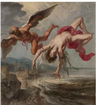
Figure 2.2 – Painting showing Icarus falling into the Aegen Sea. ...7
Figure 2.3 – Google.com map retrieved March, 2014. ...7
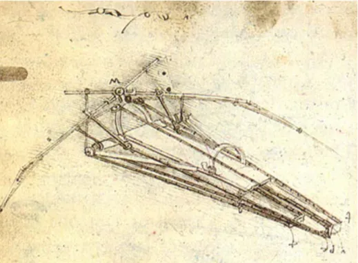
Figure 2.4 – Leonardo da Vinci Human Powered Ornithopter (1485). ...8
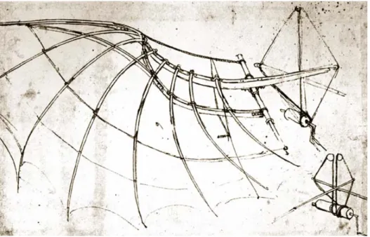
Figure 2.5 – Wing Structure and Control System. ...9
Figure 2.6 – Flying Machine. with Operator. ...9
Figure 2.7 – Gliding Flight. ...9
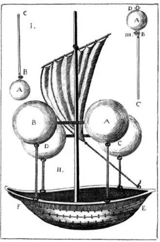
Figure 2.8 – Father Francesco Flying Boat. ... 10
Figure 2.9 – Montgolfier’s First Balloon. (Jeppesen, 2006) ... 11
Figure 2.10 – Charles Balloon is attacked by terrified villagers. ... 12
Figure 2.11 – Balloon with Cage carrying Sheep, Duck and a Rooster. ... 13
Figure 2.12 - Description of the Montgolfier Balloon. ... 14
Figure 2.13 – Balloon used in the battle of Fleurus. ... 14
Figure 2.14 –John Jeffries Balloon with Wings and Oars. ... 15
Figure 2.15 – Henri Giffard Steam Engine Balloon. ... 15
Figure 2.16 – Drawing of Launoys and Bienvenue’s model Helicopter. ... 16
Figure 2.17 – Sir George Cayley Gliders from 1804 to 1852. ... 17
Figure 2.18 – Cropped print of the Aerial Steam Carriage “ARIEL” in 1843. ... 18
Figure 2.19 –Stringfellow’s 10 Foot Wingspan Monoplane (1847). ... 18
Figure 2.20 – Drawings of Félix du Temple’s 1874 Tractor monoplane. ... 19
Figure 2.21 – Otto in mid-flight 1895. ... 19
Figure 2.22 – Chanute-Herring Glider in 1896. ... 20
Figure 2.23 – Wright Brothers 1899 Kite. ... 21
Figure 2.24 – 1900 Glider being used as a Kite. ... 22
Figure 2.25 – Wright Brother’s Wind Tunnel Replica. ... 23
Figure 2.26 – October 10th, 1902 Flight. ... 23
Figure 2.27 – October 24th, 1902 Flight. ... 24
x
Figure 2.29 – November 9th, 1904. ... 25
Figure 2.30 – October 4th, 1905 Flight. ... 25
Figure 2.31 – Practice Flight in Woodland, CA. ... 26
Figure 2.32 – Kemp Engine. ... 27
Figure 2.33 – Bob Gonzales and Paragon Propeller. ... 27
Figure 2.34 – Gonzales Company Trademark. ... 27
Figure 2.35 – Gonzales #1 Biplane. ... 27
Figure 2.36 – Gonzales #1 in Hiller Museum. ... 28
Figure 2.37 – Lawrence Sperry gyroscope. ... 29
Figure 2.38 – Bleriot XI in Flight. ... 30
Figure 2.39 – 1900 to 1919 Zeppelins. ... 33
Figure 2.40 – Airplane availability at start of WWI ... 34
Figure 2.41 – 1915 Caproni Ca.1. ... 35
Figure 2.42 – 1918 Macchi M.7. ... 35
Figure 2.43 – 1915 Curtiss JN-4. ... 36
Figure2.44 – 1918 Curtiss NC. ... 36
Figure 2.45 – 1912 Royal B.E.2. ... 37
Figure 2.46 – 1919 Vickers Vimy. ... 37
Figure 2.47 – 1915 Lloyd C.II. ... 38
Figure 2.48 – 1918 Ufag C.I. ... 38
Figure 2.49 – 1909 Bleriot XI. ... 39
Figure 2.50 – 1920 SPAD S.XX. ... 39
Figure 2.51 – 1914 Albatros B.II. ... 40
Figure 2.52 – 1918 LVG C.VI. ... 40
Figure 2.53 – Aviation School at Vila Nova da Rainha. ... 42
Figure 2.54 – Sacadura Cabral portrait. ... 43
Figure 2.55 – Sacadura on a Morane Saulnier airplane, Vila Nova da Rainha,1917. ... 43
Figure 2.56 – Reproduction of the original card of the Lisbon to Rio de Janeiro Trip. ... 44
Figure 2.57 – Precision Sextant used by Gago Coutinho. . ... 45
Figure 2.58 – Gago Coutinho portrait. ... 45
xi
Figure 2.60 – “Lusitânia” Hydroplane. ... 46
Figure 2.61 – Gago Coutinho and Sacadura Cabral. ... 47
Figure 2.62 – Navy and Curtiss Aeroplane NC-4. ... 49
Figure 2.63 – NC-4 TAs Route . ... 49
Figure 2.64 – Vickers Vimy aircraft of Captain John Alcock and Lieut. A.W. Brown. . 50
Figure 2.65 – “New Orleans” Douglas World Cruiser. ... 52
Figure 2.66 – Polish P11 and P-23 Airplanes. ... 54
Figure 2.67 – German Ju52 and Ho 229 airplanes. ... 56
Figure 2.68 – Australia Wirraway and Boomerang Airplanes. ... 57
Figure 2.69 – FrenchLeO 25 and VG-33 Airplanes. ... 58
Figure 2.70 – British Siskin and Sea Fury Airplanes. ... 59
Figure 2.71 – Soviet Union Po-2 and Yak-3 airplanes. ... 60
Figure 2.72 – Finland’s 1943 VL Myrsky Storm airplane. ... 60
Figure 2.73 – Italian SM.79 and C.205 airplanes. ... 63
Figure 2.74 – US P-12 and Mauler airplanes. ... 66
Figure 2.75 – Japanese G3M and Ki-201 airplanes. ... 66
Figure 2.77 – Netherland D.XXI and F.K.58 airplanes. ... 68
Figure 2.78 – Czech A.11 and A.304 airplanes. ... 68
Figure 2.79 – Romainian 1941 IAR / IAR 81 airplane. ... 69
Figure 2.80 – Yugoslavia 1940 Rogozarski IK-3 airplane. ... 69
Figure 2.81 – Sweden 1945 Saab J21 RB Airplane. ... 69
Figure 2.82 – Airplane availability in WWII. ... 70
Figure 2.83 – Soviet Union’s Sputnik. ... 71
Figure 2.84 – US Vanguard Satellite. ... 71
Figure 2.85 – US Explorer rocket/satellite. ... 71
Figure 2.86 – Original 1958 NASA Symbol. ... 72
Figure 2.87 – US Relay 1 Satellite. ... 73
Figure 2.88 – Neil Armstrong first step on the Moon. ... 74
Figure 2.89 – ICAO’s logo. ... 75
Figure 2.90 – FAA logo. ... 75
Figure 2.91 – JAA logo. ... 76
xii
Figure 3.2 – Airbus Logo. ... 81
Figure 3.3 – Airbus A300B2, Farnborough show in 1974. ... 82
Figure 3.4 – Aerion AS2 Supersonic Business Jet. ... 83
Figure 3.5 – Boeing Logo. ... 83
Figure 3.6 – B&W (Boeing Seaplane). ... 84
Figure 3.7 – Embraer Logo. ... 86
Figure 3.8 – Embraer Offices in the World Map. ... 86
Figure 3.9 – Embraer EMB 110 Bandeirante. ... 87
Figure 3.10 – Embraer EMB 120 Brasilia. ... 87
Figure 3.11 – Embraer Lineage 1000E. ... 88
Figure 3.12 – Airbus and Boeing’s Airplane Deliveries per Continent., ... 90
Figure 3.13 – Airbus and Boeing’s Airplane Order Comparison. ... 91
Figure 3.14 – Airbus and Boeing’s Airplane Deliveries Comparison. ... 91
Figure 3.15 – 2015 Airbus, Boeing and Embraer’s Employee Comparison. ... 92
Figure 3.16 – 2015 Airbus, Boeing and Embraer’s Revenue Comparison. ... 92
Figure 3.17 – Airbus Reported Salaries in Europe and USA. ... 93
Figure 3.18 – Boeing’s Reported Salaries in Europe and USA. ... 93
Figure 3.19 – Embraer Reported Salaries in Brazil and USA. ... 94
Figure 3.20 – European Salary Comparison. ... 94
xiii
Table Index
Table 2.1 - Italian Airplanes in WWI. ... 34
Table 2.2 - American Airplanes in WWI. ... 36
Table 2.3 - Great Britain Airplanes in WWI. ... 37
Table 2.4 – Austria-Hungary Airplanes in WWI. ... 38
Table 2.5 – France Airplanes in WWI. ... 39
Table 2.6 – Germany Airplanes in WWI. ... 41
Table 2.7 – Polish Airplanes in WWII. ... 54
Table 2.8 – German Airplanes in WWII. ... 54
Table 2.9 – Australia Airplanes in WWII. ... 57
Table 2.10 – France Airplanes in WWII. ... 57
Table 2.11 – British Airplanes in WWII. ... 58
Table 2.12 – Soviet-Union Airplanes in WWII. ... 59
Table 2.13 – Italy Airplanes in WWII. ... 62
Table 2.14 – US Airplanes in WWII. ... 63
Table 2.15 – Japan Airplanes in WWII. ... 65
Table 2.16 – Netherlands Airplanes in WWII. ... 68
xv
Nomenclature
CG Center of GravityEASA European Aviation safety Agency ECOSOC Economic and Social Council
EU European Union
FAI Fédération Aéronautique Internationale FAA Federal Aviation Administration
FAR Federal Aviation Regulations FCL Flight Crew License
HP Horse-Power
ICAO International Civil Aviation JAA Joint Aviation Authorities JAR Joint Aviation Regulations
NASA National Aeronautics and Space Administration PICAO Provisional International Civil Aviation
US United States
USA United States of America WWI World War I
1
Chapter 1. Introduction
1.1. Motivation and Scope
Engineering and Philosophy are typically conceived as two mutually exclusive domains.
The perspective of some engineers and philosophers is even worse. Engineering is commonly divided into a number of different branches such as civil, mechanical, electrical, computing, etc. The same situation occurs with Philosophy. It too includes different branches: logic, epistemology, metaphysics, ethics, aesthetics, political philosophy, etc. To illustrate the situation, and the relations between philosophers and engineers, (Mitcham, 1998) asserts that “representatives of these areas, especially ethics and aesthetics, seem to have mounted canons on their areas of the philosophy island in order to fire away at selected domains of the engineering world”. Some philosophers as even gone so far as to claim that all main ethic and aesthetic failures of the 20th century are due to an engineering attitude that reduces nature to resources, e.g. (Heidegger, 1954)1. And, others assert that “technology constitutes a threat for human dignity” e.g. (Cera, 2016).
According to the classic and still standard definition that engineers give of their own profession, engineering is “the application of scientific principles to the optimal conversion of natural resources into structures, machines, products, systems and processes for the benefit of humankind” (New Encyclopedia Britannica, 1995). Then, the philosophical attack could be replaced by “Engineering is the scientific art by which a particular group of human beings destroys nature and pollutes the world in ways that are useless or harmful to human life” (Lewis C. S., 1947).
As they have become aware of such attacks engineers have become involved in the study of philosophy to be better prepared to defend themselves. However, this problem is not yet fully understood and there are no recognized engineer philosopher schools. Surprisingly, even some Liberal Arts schools (where Philosophy is also taught together with many others disciplines in a multidisciplinary context) tend to hamper the inclusion of engineering. Nevertheless, this is not a recently detected issue, and a more details will be given in the next chapter for the case of the Aerospace Engineering.
2
The first person to be considered an engineer philosopher is Ernst Kapp (1808-1896), a contemporary of Karl Marx. He was originally educated as a philosopher, but emigrated from Germany to the “Central Texas in the United States, where he became a pioneer and developed a view of technology as a complex extension or projection of human faculties or activities” (Mitcham, 1998). He was the first person to call this philosophical anthropology of technology by “philosophy of technology” or “philosophy of engineering”. Peter Engelmeier (1855-1941) was one of the founders of the Russian professional engineering, and while talking about “philosophy of technology” he was a defensor of including knowledge about the social impact and influence of technology into the engineer education (Mitcham, 1989). The most nuclear contributor to the engineering philosophy is Friedrich Dessauer, the inventor of deep-penetration x-ray therapy. For the inventor, the first element in the creation of a technical object is the presence of human purpose. But this should not be identified either with individual or social needs. The absence of advanced technology in the prehistoric world demonstrates that individual needs alone will not produce it. Dessauer introduced the idea that a stable form of an engineering invention has a metaphysical reality prior to being brought into the physical world, transcending the Kant’s system that things in themselves are always beyond the bounds a positive knowledge. This remains true for natural objects, but for Dessauer technological objects can be known as they are in themselves (Mitcham & MacKey, 1983).
Engineers actually face problems internally or professionally that they admit cannot be resolved simply with engineering methods alone such as professional ethical issues. The ethics of technology is presently characterized by a diversity of approaches (cultural, political, engineering, computer, etc.) studied by scholars with diverse backgrounds and they do not always consider themselves primarily ethicists of technology. The ABET criteria for the engineering graduate, after asserting that competence in communication “is essential for the engineering graduate”, it is further affirmed that “an understanding of the ethical, social, economic, and safety considerations in engineering practice is essential for a successful engineering career” (Franssen, Lokhorst, & Ibo, 2015)2.
With (Mitcham, 1994) a broader approach to the philosophy of technology emerged that is concerned with the technology itself and that aims to understand both the practice of designing and creating artifacts (including artificial processes and
3
systems) and the nature of thing so created. The inherent complexity and practical efficacy of modern technologies call forth diverse kinds of thinking – scientific and technical, of course, but also economic, psychological, political, and so forth.
1.2. Research Design and Thesis Outline
The present study is the natural continuation of the participation of the author in a project between American (Colorado School of Mines, University of Vermont, Pennsylvania State University) and the European (Université d´Orléans, Università degli Studi di Napoli "Federico II" and Universidade da Beira Interior) Universities ten years ago. The project ICEE-IT ("Interdisciplinary / International Curriculum on Energy and the Environment: Innovative Technologies") was funded under the "Program for Cooperation in Higher Education and Training"3 of the European Union. The objectives of the project were to develop an interdisciplinary curriculum revolving around the technical, economic, social, political, and cultural aspects of energy and the environment. In the present study the perspective is quite similar, but the focus is confined to economic aspects of Aerospace Engineering.
Engineering was a recognized human activity at a certain period of the history (17th / 18th centuries) when some militaries designed, constructed, operated, and maintained fortifications and engines of war. The attempt to transfer those activities into non-military applications gave rise to the “civil engineering”, and presently each branch of engineering has a specific path. Engineering has continued to change geographically and socially, and needs to be aware of its past to enrich its present. So, in the Chapter 2 of the present work an excursion to the history of the Aeronautical Engineering in parallel with the Philosophy and Ethics is made in order to identify the relationship between them. Chapter 3 is devoted to the description of the methodology employed and selection of economic data available related to Aerospace Engineering, and its subsequent analysis. The last chapter contains the main conclusions of this study and some suggestions for future work.
5
Chapter 2. Philosophy and Ethics of
Aerospace Engineering
2.1. Historical Developments
According to Aristoteles, philosophy originated when human beings replaced speech about gods or the gods with speech about phusis (Greek) or nature (Latin). Probably Philosophical reflection on technology is about as the same age. In the Plato idea technology learns from or imitates nature, while for Aristoteles there is an ontological distinction between natural things and artifacts: the former have their principles of generation and motion inside, whereas the latter are generated only by outward causes.
The present study only approaches the field of Aeronautical Engineering that includes research, design, development, construction, testing, science and technology of aircrafts, including spacecraft. Aerospace Engineering is divided by nature in two independent but relates subjects; the aeronautical engineering while on Earth’s gravitational atmosphere and astronautical engineering while on outer space (Encyclopaedia of Aerospace Engineering, 2010).
In 8th Century Before Christ, the poet Homer4 writes that in Greek mythology a skilled craftsman5 named Daedalus created a wide dancing ground for Ariadne (King Minos daughter) as well as the famous Labyrinth on the Greek Island Crete. Story tells that this labyrinth was intended to keep a monster half bull-half man (son of Pasiphae, wife of King Minos) away from the community. It was so well built that only Daedalus knew how to get out of it and because of that knowledge King Minos imprisoned Daedalus in a tower in Crete. It is uncertain that this labyrinth was ground level and flat as common mind thinks as it could have been a tall building with multiple floors creating that wide area for dancing but as well as the tower mentioned to keep Daedalus. Trying to escape, Daedalus created wings for himself and his son Icarus (Figure 2.1). He tied and maintained feathers together using
4http://en.wikipedia.org/wiki/Homer; Retrieved 1/10/2014.
5 “This is the workshop of Daedalus,” wrote Philostratus of Lemnos in Immagines (1.16), “and
about it are statues, some with forms blocked out, others in a quite complete state in that they are already stepping forward and give promise of walking about. Before the time of Daedalus, you know, the art of making statues had not yet conceived such a thing”.
6
strings and wax that could suspend them on the beaten air while moving their arms. Daedalus told his son not to fly too high due to the heat of the sun so the wax wouldn’t melt, and not too low so the sea water wouldn’t get his feathers wet.
Homer states that they fled the island of Crete flying thru Levitha (previously known as Lebynthos), Samos and Delos. In the meantime, Icarus flew too close to the sun causing the wax on his wings to melt falling into the Aegean Sea (Figure 2.2). Icarus body was carried ashore by the sea currents and discovered by Heracles which recognized the body, buried it and named that island Ikaria in his memory (Graves, 1955).
Figure 2.1 - Daedalus building Wings for his son Icarus.6
Figure 2.3 is intended to show the possible flight path from Daedalus and Icarus between Crete, Levitha, Samos and Delos. The island of Ikaria is also identified where the body of Icarus was found and buried.
Daedalus continued his flight towards Sicily, ruled by King Cocalus of Kamikos, where he gave his wings as an offering to god Apollo.
7
Figure 2.2 – Painting showing Icarus falling into the Aegen Sea.7
Figure 2.3 – Google.com map retrieved March, 2014.
7 Jacob Peter Gowy, La caída de Ícaro, óleo sobre lienzo, 195 x 180 cm, Madrid, Museo del
Prado - https://www.museodelprado.es/imagen/alta_resolucion/P01540_01.jpg; Retrieved 1/10/2014.
8
Inserted in an era of amazing artistic talent, Leonardo da Vinci designed several flying machines in Italy around years 1485-1490. These “flying machines” had similarity to the Greek Daedalus and Icarus hand-made wings but with further structural built from the study of birds flying. These wing-flapping machines so called ornithopter8 (from Greek “ornithos” bird and “pteron” wing) were based on a platform where the human rests lying down and with the use of hand-levers, foot pedals and pulleys is able to control this type of machine. Although this inventor designed these machines late 1400’s, its manuscripts and notebooks were only known to public centuries after.
Figure 2.4 shows what seems to be the first drawing from this early inventor and engineer. It is visible the structural frame and hand lever movement. Several drawings from this author were discovered in different phases of development. Figure 2.5 – Wing Structure and Control System. shows a wing structural design with detail how it would work using pulleys and ropes. Figure 2.5 – Wing Structure and Control System. shows an operator using his feet to power the wing flapping machine using gears (pulleys) to multiple the strength movement to the wings. Figure 2.6 shows what seems to be his attempt to understand and study gliding flight.
Figure 2.4 – Leonardo da Vinci Human Powered Ornithopter (1485).9
8http://en.wikipedia.org/wiki/Ornithopter; Retrieved 2/02/2014. 9http://wanderling.tripod.com/fly1.jpg; Retrieved 2/02/2014.
9
Figure 2.5 – Wing Structure and Control System.10
Figure 2.6 – Flying Machine. with Operator.11
Figure 2.7 – Gliding Flight.12
10http://wanderling.tripod.com/fly3.jpg; Retrieved 2/02/2014. 11http://wanderling.tripod.com/fly6.jpg; Retrieved 2/02/2014. 12http://www.flyingmachines.org/davi.html; Retrieved 2/02/2014.
10
A couple of powerful metamorphoses in Leonardo's approach to flying machines and flying occurred as he went from the theory of flight to actually attempting flight. Beyond a theoretical point of view, their works had also a provision of new knowledge for the understanding of aerodynamics; he depicted turbulent flows; - and in 1507 he introduced the term - “turbulenza” - turbulence.
In the final of the seventeenth century the influences of Galileo (1564-1642), Descartes (1596-1650), Newton (1596-1642), and their followers induced a vision of the world in an Aristoteles’s way.
The idea of flying ships initiated in the 17th and 18thcentury where in 1670 Father Francesco Lana de Terzi13, identified as the “Father of Aeronautics”, draw a ship being levitated by copper vacuum-spheres (see Figure below).
Figure 2.8 – Father Francesco Flying Boat.14
13http://www.faculty.fairfield.edu/jmac/sj/scientists/lana.htm; Retrieved 2/07/2014. 14http://en.wikipedia.org/wiki/Francesco_Lana_de_Terzi; Retrieved 2/07/2014.
11
In spite of all of these attempts for raising funds and drawings, only in June of the year 1783 the French Montgolfier Brothers created the hot air balloon15. Suddenly others joined this idea modifying initial design, development and operation of these balloons. This first balloon was created in linen sackcloth with rag paper lining and connected using approximately 1800 buttons. This first unmanned flight was a success although the rain and the sharp eyes of the official observers reaching almost 3000 feet altitude. This balloon drifted 1.5 miles from its departure location due to air currents and burned when it reached the ground again. Although it burned, their project was a tremendous success and the Montgolfier Brothers began to make another balloon. This next balloon was intended to demonstrate their invention before the Academy of Science in Paris with the intent of raising funds for this new field of engineering.
Figure 2.9 – Montgolfier’s First Balloon. (Jeppesen, 2006)
When they arrived to Paris, they discovered that the Academy already gave a grant to a physicist named Jacques Alexander César Charles (Gay-Lussac, 1802). Mr. Charles decided to use hydrogen to lift the balloon and with the help of the Robert Brothers16, they dissolved rubber in turpentine allowing the silk taffeta fabric (previously identifies as linen sackcloth with rag paper lining) and the union between these fabric panels. In August 27th of 1783, Charles and his workers released this
15http://en.wikipedia.org/wiki/Montgolfier_brothers#cite_note-Gillispie-2; Retrieved
2/07/2014.
16 Federation Aeronautique Internationale, Ballooning Commission, Hall of Fame, Robert
12
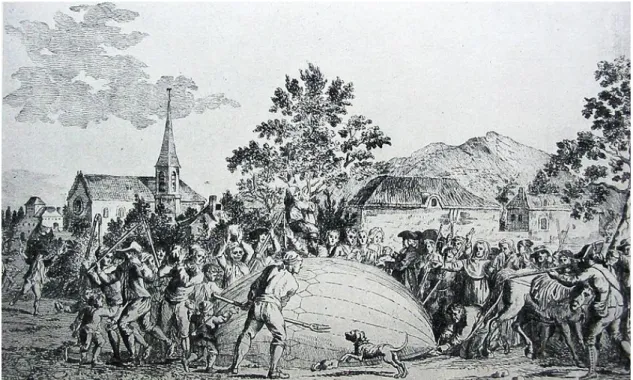
balloon where in less than two minutes rose around 1500 feet and disappeared in the clouds. In less than an hour, this balloon hit the ground 13 miles north of Paris scaring the peasants where they attacked the crashed balloon with pitchforks17 (see Figure 2.10).
Figure 2.10 – Charles Balloon is attacked by terrified villagers.18
The Montgolfier Brothers continued their work and were able to get financing from the Academy of Science and the Ministry of Finance. A second balloon was created and it passed a test flight while held using ropes however rain present next day forced them to cancel the balloon ascension.
Within a week, the Montgolfier brothers developed another balloon but this time made of taffeta cloth and wallpaper covered reinforced with varnish on its exterior and paper lined inside. With 41 feet diameter and a cage to carry animals, this third balloon was ready to take flight. On September 19th, 1783 King Louis XVI accompanied by Maria Antoinette and the French Court at Versailles watched the eight-minute flight that was carrying a sheep, a duck and a rooster (Figure 2.10). The balloon raised 1500feet and landed safely 2 miles after – this was another tremendous success to the Montgolfier Brothers.
17 Today in Science, The Montgolfier and Charles Balloons, from 1911 Encyclopedia Britannica. 18http://en.wikipedia.org/wiki/File:WasserstoffballonProfCharles.jpg; Retrieved 2/20/2014.
13
Figure 2.11 – Balloon with Cage carrying Sheep, Duck and a Rooster.19
In spite of his father request, Étienne Montgolfier was the first un-official human in history to be airborne while tethered to the ground. Because of a promise to his dad, this fact was never published but written in a letter to his wife and made public years after. Using a Montgolfier balloon Pilatre de Rozier and the Marquis François Laurent (le Vieux d'Arlandes) in November 21st of 1783, made the first free flight by humans (Figure 2.11). On October 15th 1783, the Montgolfier Brothers launched a tethered balloon with Jean-François Pilâtre de Rozier, a chemistry and physics teacher, aboard. He stayed aloft for almost four minutes.
After this amazing achievement the Robert Brothers continue on their hydrogen balloon development and with these two types of balloons, hot air and hydrogen, the world of aviation was initiated. On June, 26th 1794 Napoleon’s assigned a balloon to the Republic army for terrain surveillance. Shortly after ballooning became super popular spreading across the world for pleasure and military actions (Figure 2.13).
19 National Air and Space Museum, Smithsonian Institution, Washigton, United States of
14
Figure 2.12 - Description of the Montgolfier Balloon.20
Figure 2.13 – Balloon used in the battle of Fleurus.21
20http://en.wikipedia.org/wiki/File:1783_balloonj.jpg; Retrieved 2/20/2014.
21http://www.sciencemuseum.org.uk/objects/penn-gaskell_collection/1946-125.aspx;
15
These balloonists kept improving until the so well-known dirigibles. These dirigibles are balloons with the ability to be steerable. These became semi-rigid where they are able to levitate due to internal gas pressure (lighter than air) balancing and overcoming its mass and rising.
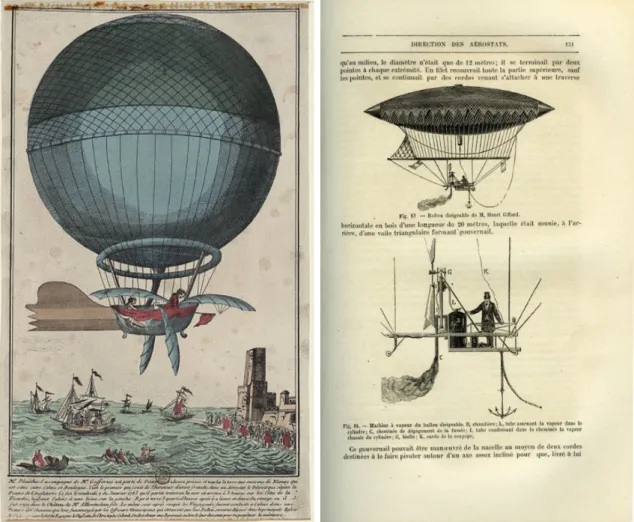
In November 30th of 1784, John Jeffries and Jean Pierre Blanchard tried to maneuver a hydrogen balloon using wings and oars (Figure 2.14) followed by Henri Giffard in 1852 using a 3 Horsepower (HP) steam engine to rotate a propeller able to fly for 6 miles per house (Figure 2.15).
Figure 2.14 –John Jeffries Balloon with Wings and Oars.22
Figure 2.15 – Henri Giffard Steam Engine Balloon.23
22http://www.loc.gov/exhibits/treasures/images/wb0109s.jpg; Retrieved 3/11/2014. 23
16
From 1852 to 1914 dirigible balloons undergone Zeppelin’s and went from semi-rigid to aluminum sheet (fully-rigid frames). In the year 1914, also known as the start of World War I (WW I), the latest and unique Zepellin LZ4 was used for military purpose. From Charles Gibbs-Smith, British historian, “the kite is in reality a primitive airplane – a craft supported in the air by the action of wind upon an inclined surface – and the windmill is a propeller.” There are records around the 5th Century B.C., that the Chinese invented the kite and that the windmill originated from Rome in the 12th Century. Only later in 1784 the windmill was given the proper aeronautical importance and that same year Professor Launoy and Bienvenu created a simple helicopter with rotors on both ends of a pole (Figure 2.16). Monsier Vallet created and tested a propeller on a river boat and a year later, in 1785, tested it on balloons. This propeller was the first attempt to propel balloons. The term propeller has Latin origin “propeller” meaning drive forward, translated as an airscrew in British and a revolving fan (moulinet) in French.
Figure 2.16 – Drawing of Launoys and Bienvenue’s model Helicopter.24
The airplane as we know it nowadays started with Sir George Cayley25 who identified physics laws as lift, drag and thrust as well as the mechanical problem of flight – “to make a surface support a given weight by the application of power to the resistance of the air.” This was quite an unnatural conclusion since there is no example of such idea in the nature. On his three published articles (“On Aerial Navigation”, 1809,
24 Apostolo “The Illustrated Encyclopedia of Helicopters”, 1984. 25http://en.wikipedia.org/wiki/George_Cayley; Retrieved 4/1/2014.
17
1810, 1810) Cayley was the first to identify the four aerodynamic forces of flight weight, lift, drag, and thrust and their relationship. Sir George studied air resistance in ballistics and windmills which led him to create the first model glider (Figure 2.17 – 1804 Glider). This glider included same paper used in kites as the wings a pole that served as a body or fuselage.
To overcome the rotation in the vertical or yaw axis, Sir George developed an empennage identifying the rudder and elevator. This glider was also equipped with a moveable weight to adjust for proper CG [Center of Gravity]. Experimenting this glider, Sir George had assistants run to the point that they would be lifted several yards at a time. In 1809 Sir George built a 200 sq. ft. full-size glider and it flew without passengers successfully but he recognized the need for power – he then spends several years trying to create a perfect solution without any good results. Getting back into building gliders, he created a small glider able to carry a ten-year-old boy while being towed by a rope. In the same year, 1853, he created a bigger glider able to carry a full-grown man. This man flew this glider freely across the valley and crashed it upon landing (Figure 2.17 – 1852 Glider).
Figure 2.17 – Sir George Cayley Gliders from 1804 to 1852.26
18
Others followed Sir George’s passion for aeronautics. William Samuel Henson and John Stringfellow created a monoplane (one wing airplane) where the wing had a new curved feature later defined as camber and a steam engine turning a six-blade propeller (Figure 2.18). First flight test wasn’t successful and Henson abandoned the project – on the other hand Stringfellow continue his adventures and in 1847 released a ten-foot steam-powered glider that flew and created attention again (Figure 2.19).
Figure 2.18 – Cropped print of the Aerial Steam Carriage
“ARIEL” in 1843.27
Figure 2.19 –Stringfellow’s 10 Foot Wingspan Monoplane (1847).28
In 1874, Félix du Temple, a French Naval Officer, created a tractor airplane (propeller pulling the airplane forward) that took off without man’s help – this was the first powered takeoff.
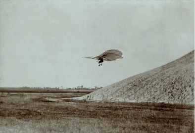
A couple of decade’s later, German engineer Otto Lilienthal logged almost 2000 flights covering between 300 to 750feet using gliders. He used fixed-wing airplanes shaped like bat wings where the pilots body mass would control the flight pattern. Otto also created foldable wings (for transport), rear elevator, leading-edge flaps
27http://www.flyingmachines.org/hens.html; Retrieved 4/1/2014. 28
http://www.wright-brothers.org/History_Wing/History_of_the_Airplane/Doers_and_Dreamers/Doers_and_Dreame rs_S.htm; Retrieved 4/15/2014.
19
and ornithopter wingtips. Otto died in 1896 after a crash but his ideas prevailed and were acknowledged.29
Figure 2.20 – Drawings of Félix du Temple’s 1874 Tractor monoplane.30
Figure 2.21 – Otto in mid-flight 1895.31
29http://www.lilienthal-museum.de/olma/ewright.htm; Retrieved 4/15/2014.
30http://www.aerospaceweb.org/question/history/q0172.shtml; Retrieved 4/15/2014. 31 United States Library of Congress's Prints and Photographs division under the digital ID
ppmsca.02546;http://en.wikipedia.org/wiki/File:Otto_Lilienthal_gliding_experiment_ppmsca .02546.jpg; Retrieved 4/15/2014.
20
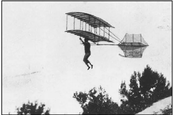
French Civil Engineer Octave Chanute built in 1896 in the surroundings of Chicago (USA), several man-carrying gliders using Cayley’s camber shaped wings and tail sections and Otto’s flight experience. He used the Pratt truss technology from bridge construction and applied it to brace the wings. A fellow young man with passion in aviation helped Chanute and successfully flew over Indiana Dunes on the shore of Lake Michigan on a kite based on work of German Otto Lilienthal (Figure 2.22). Later on the Wright Brothers read Chanute and Lilienthal’s experiments and after a personal visit he encouraged the Wright Brothers to continue their quest in powered flights.
Figure 2.22 – Chanute-Herring Glider in 1896.32
As mentioned above, Orville and Wilbur Wright, also known as the Wright Brothers, were not the first ones to develop and experiment aircrafts. They were however the first ones to successfully add controls to the aircraft allowing a fixed-wing powered flight possible.33 With their printing presses, bicycles manufacturers, motor and other mechanical components experience they realized that they needed to control equilibrium while in flight developing the three-axis control.34 After reviewing prior
32http://spicerweb.org/Chanute/ImagesCont/fly_nice.jpg; Retrieved 4/24/2014. 33http://en.wikipedia.org/wiki/Wright_brothers.
34 “Inventing a Flying Machine - The Breakthrough Concept”, The Wright Brothers and the
21
flight attempts and their reported experience from others, as mentioned above, Wilbur noted thru the study of birds that the angle at the end of the wings made them roll left or tight (Tobin, 2004). They thought that if they would be able to control by banking or leaning to one side, similar to the body motion with Chanute’s glider they would be able to control side wind flows allowing continuous flight. This idea brought them to wing-warping effect using a long inner-tube (Tobin, 2004). Figure 2.23 represents Wright Brothers 1899 kite where it shows how they achieved the wing warping using strings while in flight for control. It is visible their thought process how to control the wing ends using their hands while linked thru strings.
Figure 2.23 – Wright Brothers 1899 Kite.35
That same year, Wilbur tested the warping wing by creating a biplane kite with a 5 feet wingspan where he tried various parameters and warping amounts. After reviewing Chanute-Herring’s design, along with the information that Lilienthal published plus Sir George Cayley camber wing principle, the Wright Brothers developed a glider that contained most of the aeronautical principles from those mentioned above plus the fact of a forward horizontal elevator to help them in case of a nosedive.36 Wilbur Wright flew in Kitty Hawk this glider while several men held
35 Part of “The Dream of Flight” online exhibit in the American Treasures section at the U.S.
Library of Congress; Retrieved 4/25/2014.
36 Wright, Wilbur.“Some Aeronautical Experiments” Western Society of Engineers, September
22
tether ropes to control this aircraft (Crouch, 1989)37. Figure 2.24 shows the forward horizontal elevator, the cambered wings principle as well as the “Pratt truss” bridge design.
Figure 2.24 – 1900 Glider being used as a Kite.38
With the challenge of the amount of lift necessary versus the human weight, the Wright brother developed another glider with a large wing area but faces disappointment as the lift desires was only one-third of the calculated and the glider wasn’t responding to wing wrapping inputs.39 Suspicious that previous published studies were incorrect, the need to save overall costs in test flights and aircraft; they built a six-foot wind tunnel (Figure 2.25) and performed various tests on reduced scale wings.
With these wind tunnel tests, the Wright brothers discovered among other crucial parameters that longer and narrower wings would increase the lift-to-weight ratio. With this principle, they were able to counterbalance lift for a steady flight while overcoming issues like drag and weight amounts.40 In October 1902 they resume their actual testing and applied the knowledge gathered from the wind-tunnel. First flight in October 10th (Figure 2.26) was done using a steerable rear rudder, replacing the double fixed rudder and a couple of weeks later in October 24th (Figure 2.27)
37 pp. 188-189. 38
http://www.wright-brothers.org/Information_Desk/Just_the_Facts/Kites_&_Gliders/Kites_&_ Glider_images/1900-Wright-Glider-kited-at-Kitty-Hawk.jpg .
39 “1901 Wright Glider”, Wright Brothers Aeroplane Company; Retrieved 04/29/2014. 40“Kitty Hawk in a Box” Wright Brothers Aeroplane Company; Retrieved April 30, 2014.
23
tested using a moveable rudder with the intent to align the aircraft while banking and leveling after turns.
Figure 2.25 – Wright Brother’s Wind Tunnel Replica.41
Figure 2.26 – October 10th, 1902 Flight.42
Due to the success of controlled flight, they moved on to a powered flight for continuous flight. They believed that a powerful engine was not the solution for proper flight control and with the help of Charlie Taylor, their mechanic at the bicycle shop they developed their own custom engine in 6 weeks (Crouch, 1989)43.
41 Dodson, M.G. “An Historical and Applied Aerodynamic Study of the Wright Brothers' Wind
Tunnel Test Program and Application to Successful Manned Flight.”US Naval Academy, Technical Report, Volume USNA-334, 2005; Retrieved: 04/29/2014.
42 Library of Congress,ppprs 00604. http://hdl.loc.gov/loc.pnp/ppprs.00604; Retrieved April
30, 2014.
24
The so well-known Wright Flyer I was made out of spruce wood, home-design and carved propellers and a cast aluminum engine block made at the bicycle shop.44 In December 17th, 1903 they made successful flights of 120 feet length in 12 seconds (Figure 2.28) and later on one of 200 feet.
Figure 2.27 – October 24th, 1902 Flight.45
Figure 2.28 – Wright Flyer I 1st Flight December 17th, 1903.46
44“Milestones of Flight - 1903 Wright Flyer”-Smithsonian National Air and Space Museum. 45 Library of Congress,ppprs 00598, http://hdl.loc.gov/loc.pnp/ppprs.00598; Retrieved April
30, 2014.
46 Library of Congress,ppprs 00626. http://hdl.loc.gov/loc.pnp/ppprs.00626; Retrieved April
25
Flight tests continued as well as aircraft improvements creating the Wright Flyer II and III in 1904 and 1905 respectfully. They continued to learn with their experiences and increasing flight lengths and speeds (Figure 2.29 and Figure 2.30).
Figure 2.29 – November 9th, 1904.47
Figure 2.30 – October 4th, 1905 Flight.48
In the next couple of years, the Wright Brothers focused on trying to sell their flying machines to the US and European government with no success. Trying to overcome this obstacle, they traveled to France where they met a lieutenant from the US Army Aeronautical Division which persuaded his superiors to give the Wright Brothers a chance to show what they accomplished. In 1907 Wilbur sailed towards France and Orville went to Washington, US where they would demonstrate that they could fly with one more human person closing on the agreement of manufacturing aircrafts for the US Army and a French company. With successful flights they were able to build aircrafts under these two contracts and this was the beginning of the Wright Company (Crouch, 1989).49 Mid 1910 the Wright brothers change the aircraft design moving the elevator to the back to help control the climb and descent at higher speeds. Several fatal Army accidents caused the cancelation for that contract under the statement that the aircraft was “dynamically unsuited for flying”.50
47http://en.wikipedia.org/wiki/File:WrightFlyer1904Circling.jpg; Retrieved April 30, 2014. 48 Library of Congress, ppprs 00616 http://hdl.loc.gov/loc.pnp/ppprs.00616; Retrieved April
30, 2014.
49 pp. 410.
26
In the meantime, a series of patents issues and lawsuits took place between the Wright Company and Glenn Curtiss (Curtiss Aeroplane Company) which refused to pay license fees to the Wrights. Court judges gave the Wright Company the reason and Curtiss had to pay however in 1917 with World War I, the US Government demanded a cross-licensing organization called Manufacturers Aircraft Association where each member had to pay fees for the use of aviation patents, including its original developers.51,52 In 1929 Curtiss-Wright Company was created and they are still in business making high-tech components for the aerospace industry.53
Another important mark in history was the forgotten Gonzales Brothers (Figure 2.31). They did not invent the airplane but they continued the Wright Brothers legacy and similar business plan. Will and Arthur Gonzales were two young twin boys with third grade education, a passion for flying and no funds to accomplish their goal. They started with designing and building larger size kites and soon gliders carrying people.
Figure 2.31 – Practice Flight in Woodland, CA.54
In 1908 with the hope to move forward to powered flight they started the design of Gonzales #1 biplane that would accommodate an engine allowing this aircraft to take off from the ground. The engine selected was an in-line 4-cylinder Kemp Engine (Figure 2.32) and a Paragon propeller (Figure 2.33) all for $450 – expensive at the time. While in San Francisco, California they couldn’t perform flying tests and
51 Wicks, Frank. “Trial by Flyer” at the Wayback Machine (archived June 29, 2011) Mechanical
Engineering 100 Years of Flight; Retrieved from Web Archive 04/30/2014.
52Glenn Curtiss and the Wright Patent Battles. Centennialofflight, 2003. Retrieved
04/30/2014.
53http://www.curtisswright.com.
27
therefore disassembled the aircraft and moved to Woodland in Northern California where they had long flat areas for temporary flying tests.
Figure 2.32 – Kemp Engine.55 Figure 2.33 – Bob Gonzales and Paragon Propeller.56
As mentioned before, due to patent infringement issues, the Wright Brothers visited the Gonzales Brothers shop and their biplane. They found no patent infringements and even lend them some money. In August 8th, 1918 they relocated once more to Los Angeles, California where they modified their initial design with tail feathers and ailerons. They created and established the Gonzales Bros. Aeroplane Manufacturing and Supply Company (Figure 2.34) but there’s no history of any other airplanes or designs.
Figure 2.34 – Gonzales Company Trademark.55
Figure 2.35 – Gonzales #1 Biplane.56
In 1972 the Gonzales#1 biplane passed on as an inheritance within the family where it was repaired and back into working conditions. After various air shows and a 12
55https://doolittlecenter.org/Publication2GonzAero.pdf; Retrieved 05/01/2014. 56https://doolittlecenter.org/html/gonzales.html; Retrieved 05/01/2014.
28
year display at the Hiller Museum in San Carlos, California (Figure 2.36) the original Gonzales biplane now rest for educational purposes inside of a family hangar.54,55
Figure 2.36 – Gonzales #1 in Hiller Museum.56
From the Wright Brothers published developments to World War I, the aviation industry boomed with different airplane constructions, with first flights and their records. It became an industry from the early inventor to their business partners. As stated above, upon the return of the Wright Brothers to flying, they discovered that Europe was far advanced due to their government support. By 1910, France was the world leader in aviation followed by Britain, Germany, Russia and Italy. The two remarkable US inventors, Wright Brothers and Glenn Curtiss, were busy fighting their patents and lawsuits on each other while Europe continues with their airplane and technology developments.
Patent infringements were filed by the Wright Brothers not only in the US but in Germany, France and Great Britain. The German claim lost its ground due to the fact that Octave Chanute gave a conference in Berlin University describing wing warping before the Wright’s patent application was issued. The French claim, against six different manufacturers, was accepted and ruled-out in favor of the Wright Brothers. However, the plaintiffs defended their point with extensions and countersuits until the expiration of those patents in 1917. Great Britain government
29
was the only country that gave patent rights to the Wright Brothers and that actually paid them for those infringements.
In 1913, the Wright Brothers filed a patent for automatic stability using a pendulum to control yaw, roll and pitch changes. This development was not state-of-the-art, as Lawrence Sperry had developed the gyroscopic stabilizer in 1914 (see Figure 2.37). At the same time, while Wrights airplanes had three levers to warp the wings, to set the rudder and to adjust the elevator, the Curtiss airplanes possessed a control wheel that allowed the pilot to pull or push to control the elevator, turning to control the rudder and a shoulder yoke to control the ailerons. The airplane/aircraft industry was growing rapidly in both military and civil use.
With the start of aviation industry, the need for engines, flight schools and airports was inevitable. Engines from two to sixteen cylinders in vertical, horizontal, radial, V, opposed or tangent format were created mainly by France, Germany and the US. Since early 1909, Louis Bleriot started mass production of the Bleriot XI (Figure 2.38) airplane and by 1911 he logged the 500th Bleriot out of his factory. For all of these airplanes he discovered the need to teach their owners or future pilots how to fly. Airplane owners were taught to fly for free, while other students had to pay a fee plus damaged parts.
Figure 2.37 – Lawrence Sperry gyroscope.57
57
http://www.wright-brothers.org/History_Wing/History_of_the_Airplane/Decade_After/Girding_
for_Battle/Girding_for_Battle_images/Lawrence-Sperry-and-gyroscopic-stabilizer.jpg; Retrieved 05/05/2014.
30
Figure 2.38 – Bleriot XI in Flight.58
The construction of airports or a specific area dedicated for taking-off and landing was of extreme importance for the safety of the airplane, structures surrounding it and their pilots. Open land pastures with easy access to public, good year-round weather conditions and the ability to build hangars, living quarters made the perfect landing strips. Some of these locations were also close to water beds allowing floats (pontoons) take-offs and landings. The military used their fields for training and maneuvers while manufacturers used their designated fields for flight tests and demonstrations.
With the need to guide pilots while flying from one location to the other, the need for ground references and defined directions began. These references were initially on the ground, painted on top of building roofs or by captive balloons. Due to the fact that pilots used ground references with the help of a compass to guide them thru flight, the French and German military published in 1911 the first aeronautical maps individually. In that same year, the First International Congress of Aerial Law met in Paris and from these meetings a first set of laws became official.
These initial laws were simple:
• Air traffic is free but subjected to that nations regulations (if applicable);
58 Library of Congress, ggbain 04066. http://hdl.loc.gov/loc.pnp/ggbain.04066; Retrieved
31
• Every aircraft needs to be registered and the residence if its owner determines its country;
• Every aircraft displays a mark of its nationality;
• Landings could be done in an open field but not within cities or military infrastructures;
• It is strictly forbidden to drop objects that could hurt people or property, and;
• Wrecked or abandoned aircrafts could be claimed by its owner one year of that discovery upon payment of search, salvage and preservation costs.
These rules got iterated several times getting more and more complex. These rules history and understanding will be studied and developed in the Regulations chapter. World War I was the first major conflict to feature a wide variety of military aircraft as air power superiority; countries were assembled in two opposing alliances:
• Allied Powers: France, United Kingdom, Russia, Belgium, Japan, Portugal (1916-1918), United States (1917-1918), Greece (1917-1918) Italy and others. (Italy ended its alliance with the Central Powers arguing that Germany and Austria-Hungary started the war and that the alliance was only defensive in nature; it entered the war on the side of the Allied powers in 1915);
• Central Powers: Germany, Austria-Hungary, Ottoman Empire, Bulgaria (1915-1918).
Portugal remained neutral at the start of the conflict in 1914; even though Portuguese and German governments stayed officially neutral for over 1 ½ year after the outbreak of WWI, there were many hostile engagements between both countries. Portugal wanted to comply with British requests for aid and protect its colonies in Africa, thus clashes occurred with German troops in 1914 and 1915 (South of Angola – which bordered German South-West Africa). Germany/Portugal tensions also arose as a result of German U-boat warfare, which sought to blockade the U. K., at the time the most important market for Portuguese products. Ultimately, tensions resulted in declarations of war, firstly by Germany against Portugal in March 1916.
At Mozambique along operations against German Eastern Africa in 1917, the Portuguese forces included a small squadron of a modified Farman MF.11, one of the first employments of military aircraft in Africa. During WWI, several Portuguese airmen flew in British and French squadrons; pilot Óscar Monteiro Torres became the first Portuguese airmen to be killed in an air combat.
32
German troops entered Belgium heading to France in mid-1914 using trains, trucks, cars, horses and by foot. Lighter-than-air equipment was only used for reconnaissance. WWI was mostly fought inside trenches where soldiers were protected by dirt. In the beginning German Army had six rigid-frame Zeppelins and the German Navy had two. The German Army retired their airships a couple of years later when they realized the vulnerability of these Zeppelins while flying over ground. These large, low-flying, slow-moving Zeppelins were easy target for bullets, rockets or a simple arrow transporting fire that would create these to erupt in flames. The German Navy in the other hand, continued with the use of airships, increased their fleet and attacked England early 1915. Due to the poor bomb load that these airships could carry, the Zeppelins were used to prove German’s force over their allies more than the damaged cause by them. Germany was at these early stages of war delivering the war to England but soon the British Army increased their defense system developing observation patrols, searchlights, and wires to catch German Airships while tethered by balloons suspended in air and by creating fighter airplanes capable of flying higher than the German airships.
Due to the location of both countries, Germany had to fly 20-24hr round-trip over the North Sea and rapidly found that night flying would be advantageous. Navigation was a required skill and for this they developed and used radio direction-finding equipment in early 1916. However, the cold temperatures of those regions froze airships coolants, created ice on the hull and propeller. At this point the German Navy would only carry enough fuel for that missions plus a little of reserve but this was problematic if there was a navigation error or unexpected winds. It is amazing the fact that German lost more airships due to weather and mechanic problems than the ones brought down by British forces. Although Britain possessed and developed night fighter airplanes that took off sea platforms, France, Belgium, the Eastern Front and the Balkan Peninsula were also attacked by Germany mostly by daytime due to the fact that these other countries had minimum support to fight airships. With the need to build airships and improve their building and flying skills, Germany had to build bigger, more powerful equipment to fly higher to avoid others defenses. By 1917 the Zeppelin building process was so well developed that it only took them 6 weeks to build one. Germans increased their airship volume size (from 22,000 cubic meters in 1914 to 55,000 in 1916) as well as engine power (from 600HP to 1,600HP by 1916). Figure 2.39 shows design and size evolution throughout their Zeppelins airships existence.
33
German logistics discovered that for the cost of one battleship they could build 80 airships. Although these monstrous airships frighten those under attack it was later discovered that German tactics weren’t that successfully. From a total of 125 German airships, 79 were lost (63%), totaling 441 lost lives. With false/inaccurate battle reports to higher commands, the German realized that these airships were useful for reconnaissance over water but a failure as a land bomber.
The airplanes for those involved in early stages of WWI were designed mostly for observation missions. Most of these two-seats biplanes didn’t had the performance or pay-load for much more. Graph on Figure 2.40 represents the number of aircraft available by the different countries at the start of WWI.
Figure 2.39 – 1900 to 1919 Zeppelins.59
34
Figure 2.40 – Airplane availability at start of WWI
Table 2.1 represents the airplane year, their manufacturers name and model while Figure 2.40 and Figure 2.41 show the first and last of the Italian airplane manufactured throughout the WWI period. 1915 Caproni Ca.1 was a four-seater airplane with two 100HP engines as a puller and another engine as a pusher with machine guns and the option of bomb carrying; the 1918 Macchi M.7 a single pilot airplane with one 260HP engine with machine-guns.
Table 2.1 - Italian Airplanes in WWI.60 Year Manufacturer and Model 1915 Caproni Ca.1
1917 Macchi M.5 1918 Caproni Ca.3 1918 Ansaldo A 1 Balila (Hunter) 1918 Macchi M.7 60http://www.militaryfactory.com/aircraft/ww1-aircraft-timeline.asp; Retrieved 05/02/2014. 0 20 40 60 80 100 120 140 160 180 200 United States Great Britain Austria-Hungry France Russia Number of Airplanes
35
Figure 2.41 – 1915 Caproni Ca.1.61 Figure 2.42 – 1918 Macchi M.7.62
Italy had some previous war experience in the Italy-Turkish War. Italy waterways and coast line gave upper-hand to the naval force for the military use of airplanes made domestically by Lohner, Macchi and some imported Curtiss (American airplanes).
The United States of America joined the war in April 1917 where the Army and Naval forces were recruited, trained and relocated to Europe. Some other pilots went to Canada or Britain to join the Canadian Royal Flying Corps and the British Royal Flying Corps. Others joined the French Foreign Legion Flying Corps (Légion Étrangére) while able to maintain their American citizenship. While in alliance with France, the Blériots, Nieuports and Spads airplanes were mostly used by American pilots.
Table 2.2 - American Airplanes in WWI. represents the airplane year, their manufacturers name and model while Figure 2.43 and Figure2.44 shows the first and last of the American airplanes manufactured throughout the WWI period. 1915 Curtiss JN-4 is a two seater airplane with one 90HP engine with no weapons installed (mostly used for training purposes); the 1918 Curtiss NC is a six seater airplane with
61
http://www.militaryfactory.com/imageviewer/ac/pic-detail.asp?aircraft_id=774&sCurrentPic=pi c1; Retrieved 06/02/2014.
36
three 400HP engines as a puller and another one as a pusher with machine guns and the option of bomb carrying.
Table 2.2 - American Airplanes in WWI.60
Year Manufacturer and Model
1915 Curtiss JN-4 (Jenny) 1916 Aeromarine 39 1917 Curtiss H-16 1917 Standard J-1 1918 Aeromarine 40 1918 Vought VE-7 Bluebird
1918 Curtiss NC (Navy Curtiss/Nancy Boat)
Figure 2.43 – 1915 Curtiss JN-4.63 Figure2.44 – 1918 Curtiss NC.64
Great Britain joined the war in August 1914 with 4 squadrons from the British Royal Flying Corps. These officers flew to Amiens (France) and a couple of weeks later settled in Maubeuge. The first plane brought to war was a reconnaissance two-seat biplane named B.E.2a. More joined later with more airplanes identified as B.E.2, B.E.2b, Avro, Bristol and Sopwith.
Table 2.3 - Great Britain Airplanes in WWI. represents the airplane year, their manufacturers name and model while Figure2.44 and Figure 2.45 show the first and last of the British airplane manufactured throughout the WWI period. 1912 Royal
63
http://www.westernspringshistory.org/wp-content/uploads/2014/03/WSHS-Curtiss-Jenny-Airpl ane.jpg; Retrieved 06/02/2014.
64
37
Aircraft Factory B.E.2 is a two seater airplane with one 90HP engine with the option of carrying a machine gun at the rear cockpit or bomb carrying; the 1919 Vickers Vimy is a three seater airplane with two 360HP engines with two machine guns (front and back) plus the option of bomb carrying.
Table 2.3 - Great Britain Airplanes in WWI.60
Year Manufacturer and Model Year Manufacturer and Model
1912 Royal Aircraft Factory B.E.2 1917 Felixstowe F.2
1913 Avro 504 1917 Sopwith Dolphin
1914 Bristol Scout 1917 Armstrong Witworth F.K.8 1914 Sopwith Tabloid 1917 Airco DH.9
1915 Short Type 184 1917 Royal Aircraft Gactory S.E.5
1915 Sopwith Baby 1917 Sopwith Camel
1915 Vickers FB.5 1917 Bristol F.2
1915 Royal Aircraft Factory F.E.2 1917 Airco DH.4
1915 Airco DH.2 1917 Airco DH.5
1916 Sopwith Triplane 1918 Handley Page H.P. O/400
1916 Royal Aircraft Factory F.E.8 1918 Martin MB-1/Glenn Martin Bomber 1916 Sopwith 1-1/2 Strutter 1918 Blackburn R.T.1 Kangaroo
1916 Sopwith Pup 1918 Martinsyde F.4 Buzzard
1916 Royal Aircraft Factory R.E.8 1918 Sopwith Snipe
1916 Avro 523 Pike 1918 Sopwith Rhino
1917 Fairey Campania 1918 SSZ 65
1917 Avro 529 1918 NS7
1917 Beardmore WB III/SB 3 1918 Fairey III 1917 Felixstowe F.5 1919 Vickers Vimy
Figure 2.45 – 1912 Royal B.E.2.65
Figure 2.46 – 1919 Vickers Vimy.66
65