UNIVERSIDADE DA BEIRA INTERIOR
Engenharia
Structural Analysis of a Variable-span Wing-box
Rui Filipe Martins Fernandes Cunha
Dissertação para obtenção do Grau de Mestre em
Engenharia Aeronáutica
(Ciclo de Estudos Integrado)
Orientador: Prof. Doutor Pedro Gamboa
To my family and friends
For all their support
Acknowledgements
This work has been partially funded by the European Union’s Seventh Framework Programme (FP7) under the Grant Agreement 314139. The CHANGE project (Combined morphing assessment software using flight envelope data and mission based morphing prototype wing development) is a Level 1 project involving 9 partners.
I extend my sincere thanks to all those who, through various forms, accompanied me throughout the preparation of this dissertation. The support I received at the personal and scientific levels, were crucial to this achievement. Without intending to inadvertently forget someone, I must specifically thank some of the most offered significant contributions to this project.
To my family, especially my parents, my brother, grandparents and uncles, I appreciate the support they have given me to accomplish this dream. I hope one day I can return all the effort and confidence they have in me.
I thank Professor Pedro Gamboa for his availability and opportunity given to work on this innovative topic and the knowledge imparted on various material aspects of this dissertation.
I thank Pedro Santos his understanding and the immense help throughout the time I worked with him. Besides the amount of knowledge conveyed, influenced me to take more interest in the topic of this dissertation.
I thank all partners in the CHANGE Project.
I appreciate the patience and generosity of those who contributed to the process of text and formatting dissertation’s review, identifying linguistic lapses and rectifying some of its content.
I appreciate every moment I spent with my friends and the mutual help that contributed to the success of all of us.
Last but not least I thank the families Flores da Silva, Mendes and Almeida the encourage words that they told me to continue to struggle to getting through the hard times.
Resumo
Esta dissertação de mestrado descreve o trabalho realizado para analisar a estrutura da caixa de torção de uma asa de envergadura variável. Com base no trabalho realizado anterior-mente no projeto CHANGE o principal objetivo desta dissertação é a validação do modelo nu-mérico, feito por Pedro Santos, da caixa de torção envolvente no desenho preliminar para este projeto. Primeiramente foi dimensionado o estaleiro para validar estaticamente este modelo estrutural em que se constituiu o seguinte trabalho. Através do uso de ferramentas computaci-onais de desenho (CAD) e cálculo numérico, foi projetada e construída a montagem experimen-tal. Com base em ferramentas de análise estrutural computacional, o modelo numérico permi-tiu o estudo paramétrico, um dos objetivos deste trabalho. De modo a complementar este estudo, foram analisadas várias configurações da asa preliminar para compreender a variação do peso da estrutura e da flexão de acordo com a fração da envergadura móvel. Com a ajuda de ferramentas de programação obtiveram-se dois polinómios calculados a partir das respetivas variações anteriormente descritas. Finalmente foram feitos testes experimentais no protótipo do desenho da asa preliminar.
Palavras-chave
Análise Estrutural; Caixa de Torção; Estudo paramétrico; Modelo Numérico; Morphing; Pro-jeto CHANGE; UAV; Validação.
Abstract
This dissertation describes the work done to analyse the wing-box of a variable-span wing. Based on previous work in the CHANGE project the main objective of this study is the experi-mental analysis of the wing-box structure’s prototype build at Universidade da Beira Interior, one of the CHANGE project partners. Surrounding the preliminary design of this project, a nu-merical model written, concerning a parallel work, was modified and used to analyse the mass and displacement variations according to the moving fraction and semi-span of the morphing wing-box. It was first dimensioned the jig to statically validate this structural model that con-cerns the following work. Through the use of Computer Aided Design tools and numerical cal-culation, it was designed and built an experimental setup. Based on computational structural analysis tools, the numerical model allowed the parametric study of the preliminary wing-box design comprising the mass and displacement changes in accordance of the two following pa-rameters: moving fraction and semi-span. In order to complement this study, various configu-rations of the preliminary wing-box were analysed such as the reduction of the composite sand-wich skin’s thickness. With the help of programming tools two polynomial functions were cal-culated from the respective variations previous described. Finally, experimental tests were performed on the prototype of the preliminary wing design. The numerical model was validated and the values are in good agreement.
Keywords
CHANGE Project; Morphing; Numerical Model; Parametric Study; Structural Analysis; UAV; Validation; Wing-box.
Contents
Acknowledgements ... v Resumo ... vii Palavras-chave ... vii Abstract... ix Keywords ... ix Contents ... xiList of Figures ... xiii
List of Tables ... xvii
List of Acronyms ... xvii
Nomenclature ... xxi
1.Introduction ... 1
1.1.Motivation ... 1
1.2.Benefits and challenges ... 3
1.3.Similar work ... 6
1.4.The CHANGE project ... 6
1.4.1.Technical specification ... 7
1.5.Scope of current study ... 8
1.6.Outline ... 8
2.Literature review ... 9
2.1.Shape morphing of aircraft wings ... 10
2.1.1.Wing planform change ... 11
2.1.2.Out-of-plane transformation of the wing ... 12
2.1.3.Aerofoil adjustment ... 14
2.2.Span morphing ... 14
2.3.Various combined in-plane morphing capabilities ... 17
2.4.Sweep morphing ... 19
2.5.Folding wings ... 19
2.6.Wing-box structural analysis ... 20
3.Preliminary design ... 23
3.1.Telescopic wing concept ... 23
3.1.1.Design loads ... 23
3.1.2.Wing-box concept ... 26
3.1.3.Materials ... 29
3.1.4.Actuation system ... 30
3.1.5.Preliminary wing-box design ... 32
3.1.6.Wing-box preliminary structural sizing... 35
4.Parametric study of the wing-box ... 47
4.1.Numerical model ... 47
4.2.Mass parametric study ... 50
4.2.1.Analytical representation ... 55
5.Wing-box testing ... 59
5.1.Test jig ... 59
5.1.1.Description and components ... 59
5.2.Experimental setup ... 61
5.2.1.Shear and bending moment diagrams ... 62
5.3.Results ... 65
6.Conclusions ... 67
6.1.Summary ... 67
6.2.Numerical analysis ... 67
6.3.Experimental tests ... 68
6.4.Suggestions for future work ... 68
7.References ... 69
List of Figures
Figure 1.1: Spider plot comparing performance of the base-design Firebee, the morphing
aerofoil Firebee and the morphing planform Firebee [6] ... 2
Figure 1.2: Spider plot comparison of NextGen’s fixed and morphing wings aircraft [7] ... 3
Figure 1.3: Comparison of mission profiles for a generic commercial airliner vs. a generic surveillance UAV [8] ... 4
Figure 1.4: Mission in the CHANGE project [16] ... 7
Figure 2.1: Festo, the Smartbird at different stages of flight [17] ... 9
Figure 2.2: Flying mechanism that emulates birds was conceived for planetary exploration missions [18] ... 9
Figure 2.3: Tipuana tipu (at left) and Alsomitra macrocarpa (at right) seeds [1]... 9
Figure 2.4: Categories of morphing wing [19] ... 11
Figure 2.5: In-plane shape morphing can be achieved by a) span change; b) chord length change; and c) sweep change ... 11
Figure 2.6: Out-of-plane wing morphing is possible through a) wing twisting; b) chord-wise bending; and c) and span-wise bending ... 12
Figure 2.7: Aerofoil profile variation scheme [19] ... 14
Figure 2.8: Zig-zag wing-box concept top view (at left) and isometric view (at right) [27] ... 16
Figure 2.9: Actuator configurations; (A) vertex to vertex; (B) crossed; (C) direct driving; and (D) rib to vertex [27] ... 16
Figure 2.10: 3D printed telescoping wing [28] ... 17
Figure 2.11: Wing central bay: (a) CAD model and (b) wing prototype. 1) servo motors supporting board; 2) board linkage; 3) wing-fuselage lug; and 4) upper board and actuation bay [29] ... 17
Figure 2.12: Span and chord setup (The red arrows point to the three power screws) [30] ... 18
Figure 2.13: Wing-box mechanism a) sweep mechanism after construction and b) CAD drawing of wing-box with wings [30]... 18
Figure 2.14: Progressive foldable wing of Lockheed Martin’s concept [37] ... 20
Figure 3.1: Combined V-n diagrams ... 24
Figure 3.2: Wing-box section definition (dimensions in mm) ... 27
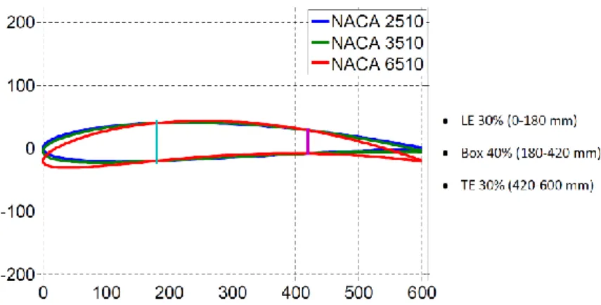
Figure 3.3: Wing-box aerofoils ... 28
Figure 3.4: Wing planform and its aerofoils (dimensions in mm) ... 28
Figure 3.5: Wing-box concept ... 28
Figure 3.6: New proposed wing planform (dimensions in m) ... 29
Figure 3.7: CAD Design of the actuation mechanism ... 31
Figure 3.8: Detailed view of IFW and OMW prototype. Notice the linear guides bonded to the corners of both components ... 31
Figure 3.9: Detailed view of the actuation system: a) assembled and b) disassembled ... 32
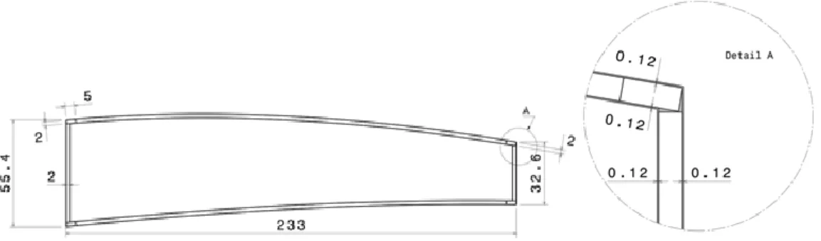
Figure 3.10: Inboard fixed wing cross section showing structure dimensions (in mm) ... 33
Figure 3.11: Outboard moving wing cross section showing structure dimensions (in mm) ... 34
Figure 3.12: Inboard fixed wing and Outboard moving wing structure dimensions in mm (not to scale) ... 34
Figure 3.13: CAD Model of the telescopic wing-box: a) extended configuration and b) retracted configuration (OMW skin added for clarity) ... 34
Figure 3.14: Load distributions for loiter wing configuration at low speed ... 36
Figure 3.16: Load distributions for high-speed wing configuration at low speed ... 37 Figure 3.17: Load distributions for high-speed wing configuration at high speed ... 37 Figure 3.18: Equivalent force system for wing-box sizing (V is the vertical force, H the horizontal force and M the pitching moment) ... 38 Figure 3.19: Total displacement of the loiter wing in the low speed condition ... 39 Figure 3.20: Inverse of Tsai-Wu strength ratio of the two main bodies that constitute the wing-box: a), b) and c) show the three layers of the inboard fixed portion and d), e) and f) the three layers of the outboard moving portion ... 40 Figure 3.21: Total displacement of the loiter wing in the high speed condition ... 41 Figure 3.22: Inverse of Tsai-Wu strength ratio criteria of the two main bodies that constitute the wing-box: a), b) and c) show the three layers of the inboard fixed portion and d), e) and f) the three layers of the outboard moving portion ... 42 Figure 3.23: Total displacement of the high speed wing in the low speed condition ... 43 Figure 3.24: Inverse of Tsai-Wu strength ratio Failure Criteria of the two main bodies that constitute the retracted wing-box at the lower speed condition: a), b) and c) show the three layers of IFW and d), e) and f) the three layers of the OMW ... 44 Figure 3.25: Total displacement of the high speed wing in the high speed condition ... 45 Figure 3.26: Inverse of Tsai-Wu strength ratio criteria of the two main bodies that constitute the retracted wing-box in the higher speed condition: a), b) and c) show the three layers of IFW and d), e) and f) the three layers of the OMW ... 46 Figure 4.1: Variable-span wing model in ANSYS Mechanical APDL: a) complete finite element model and a detail of the interface between the IFW and OMW, b) IFW layered shell and c) OMW shell ... 49 Figure 4.2: Numerical model's example of final solution (displacement) ... 49 Figure 4.3: Maximum tip deflection obtained using different number of elements ... 50 Figure 4.4: Preliminary wing-box design modifications to support the study: Case B) webs’ laminate thickness reduction and Case C) webs’ laminate and core thicknesses reduction ... 51 Figure 4.5: ANSYS’ wing-box mass and displacement as functions of moving fraction for a semi-span of 2 m: a) values given for moving fraction between 0.05 and 0.3; and b) detail of displacement curves ... 52 Figure 4.6: ANSYS’ mass and displacement analyses: a) semi-span of 2.5 m; and b) semi-span of 3 m ... 52 Figure 4.7: ANSYS data for 2 m wingspan and 5 % moving fraction: a) wing tip displacement, b) Failure Criteria and c) wing tip twist (Case A) ... 53 Figure 4.8: ANSYS data for 2 m wingspan and 20 % moving fraction: a) wing tip displacement, b) Failure Criteria and c) wing tip twist (Case A) ... 54 Figure 4.9: ANSYS data for 2 m wingspan and 30 % moving fraction: a) wing tip displacement, b) Failure Criteria and c) wing tip twist ... 55 Figure 4.10: Polynomial approximation of wing-box’s mass (Case A) ... 56 Figure 4.11: Polynomial approximation of wing-box’s displacement (Case A) ... 57 Figure 4.12: Interface variation according to different moving fractions: a) fixed wing, b) morphing wing with a moving fraction of 0.05, c) morphing wing with a moving fraction of 0.125 ... 57 Figure 5.1: Horizontal rails and component tube ... 59 Figure 5.2: Jig's dimensions in mm ... 60 Figure 5.3: Components used for the experimental tests a) load cells, b) data acquisition system and c) graduated ruler and dial analogue comparator ... 60 Figure 5.4: Components used for the experimental tests a) load transfer rib, b) rod end bearings and c) studded rod end bearing ... 61
Figure 5.6: Wing-box test bench assembly ... 61
Figure 5.7: Jig's main components ... 62
Figure 5.8: Distributed forces representation ... 62
Figure 5.9: Lift and Drag distributions along the wing's semi-span ... 64
Figure 5.10: Shear diagram ... 64
Figure 5.11: Bending moment diagram ... 65
Figure 5.12: Experimental tests' results ... 66
List of Tables
Table 1.1: Characteristics of wing-level morphing [9] ... 4
Table 1.2: Effects of wing geometric parameters on aircraft performance [10] ... 5
Table 2.1: Definitions of Discrete and Continuous Morphing [20] ... 10
Table 2.2: Air-vehicles that flew with span morphing technology [23] ... 15
Table 3.1: Required data to compute the V-n diagrams ... 24
Table 3.2: Load cases for wing-box preliminary sizing ... 26
Table 3.3: Loads for wing-box sizing ... 26
Table 3.4: Material properties ... 30
Table 3.5: Wing-box component dimensions and materials for IFW ... 33
Table 3.6: Wing-box component dimensions and materials for OMW ... 33
Table 3.7: Wing components mass from the FE model and prototype built... 35
Table 3.8: Equivalent loads ... 38
Table 5.1: Experimental tests' fore and aft loads ... 65
Table A.1: Values collected from the wing-box structural analysis for Case A) ... 74
Table A.2: Values collected from the wing-box structural analysis for Case B) ... 75
List of Acronyms
ARA Aircraft Research Association
CAD Computer Aided Design
CAM Computer Aided Manufacturing
CFD Computational Fluid Dynamics
CHANGE Combined morphing assessment software using flight envelope data and mission based morphing prototype wing development
DARPA Defence Advanced Research Projects Agency
DC Direct Current
DLR Deutsches Zentrum fur Luft und Raumfahrt
EASA European Aviation Safety Agency
FC Failure Criteria
FE Finite Element
FEM Finite Element Method
IFW Inboard Fixed Wing
LE Leading Edge
MALE UAV Medium Altitude Long Endurance Unmanned Aerial Vehicle
OMW Outboard Moving Wing
PTFE Polytetrafluoroethylene
PWM Pulse Width Modulation
PZT Piezoelectric
RC Remote Control
SMA Shape Memory Alloys
TE Trailing Edge
THUNDER Thin Layer Composite-Unimorph Ferroelectric Driver and Sensor
UAV Unmanned Aerial Vehicle
UBI Universidade da Beira Interior
UV Ultraviolet
Nomenclature
CL Wing Lift Coefficient
g Acceleration due to Gravity, m/s2
Cl Aerofoil Lift Coefficient
Cm Aerofoil Pitching Moment Coefficient
V Aircraft Equivalent Speed, m/s
α Angle of Attack, º
VC Cruise Speed, m/s
ρ Density of air, kg/m3
VD Design Dive Speed, m/s
VB Design Speed for Maximum Gust Intensity, m/s
δ Displacement, m
D Drag, N
L Lift, N
L/D Lift to Drag Ratio
n Load Factor m Mass, kg p Moving Fraction M Pitching Moment, Nm b Span, m VS Stall Speed, m/s θ Torsion, Nm S Wing Area, m2
CD Wing Drag Coefficient
CL max Wing Maximum Lift Coefficient
1. Introduction
When we admire the efficiency and elegance of bird flight in Nature, our aviation achieve-ments seem to pale in comparison. Unlike natural fliers, typical aircraft are rigid and inflexible bodies that achieve their design goals through brute force. Inspired by gliding seeds, insects, bats and the flight of birds, work done by researchers in the area of aircraft morphing offers us a chance to achieve some of the efficiency of flight in Nature with aircraft that can operate from space to roads and water. [1]
Designers seek inspiration in order to achieve the simplicity, eleganfice, and efficiency that characterize animal species obtained by thousands of years of biological evolution. [2] Birds are able to manoeuvre in flight with amazing capabilities and aggressive transitions from dif-ferent flight stages. Avian morphology permits a wide range of wing configurations, each of which may be used for a particular flight task. [3] With the ever-expanding technology in avia-tion industry, progresses were made in the area of wing design with means of changing the wing or the aerofoil shape in order to expand flight envelopes. Altering the geometry of the wing, known as wing morphing, will lead to an improved performance and/or efficiency over the entire flight of the vehicle. However, in the aeronautical field, there is neither an exact defi-nition nor an agreement between the researchers about the type of geometrical changes nec-essary to qualify an aircraft as shape morphing. Morphing is short for metamorphose and is adopted to define “a set of technologies that increase a vehicle’s performance by manipulating
certain characteristics to better match the vehicle state to the environment and task at hand”.
[4]
The deployment of conventional flaps or slats on a commercial airplane changes the geom-etry of its wings that allows the aircraft to fly at a range of flight conditions, but the perfor-mance at each condition is often sub-optimal. Moreover, these geometry changes are limited, with narrow benefits compared with those that can be achieved from an adaptable wing. Alt-hough significant geometry changes of an aircraft wing during flight may allow an approach to the optimal performance, multi-role missions are not possible with a fixed-geometry aircraft.
Morphing aircraft are capable of the best performance at all flight stages. This can be achieved by means of crowding different concepts and configurations. So, in-flight change of aerofoil or wing’s characteristics became the most sought solutions for morphing.
1.1.
Motivation
Ever since the dawn of aviation, wing morphing has been used for aircraft control. In 1903, the Wright Brothers were the first successful aviators to use wing warping in an actual flight test which enabled roll control by changing the twist of its wing using cables actuated directly by the pilot. [5] Most all of the Wrights’ predecessors who studied flight were concerned with constructing naturally stable aircraft and therefore control was less of an issue.
In the 1990s aircraft morphing focused mainly on improving the efficiency of wing and con-trol surfaces. In the twenty-first century work continues on improving flight efficiency, but advances in lightweight and smart materials, efficient innovative actuators and control systems have pushed the research and development focus to expanding the range of operational envi-ronments. This performance enhancement capability was demonstrated in Tidwell’s et. al. [6] work, where the Firebee drone base design was subjected to both aerofoil and planform opti-mization for each flight stage and manoeuvres. The positive results on the two optiopti-mization designs in comparison to the base design are plotted in Figure 1.1. The need for innovation allowed to increase energy efficiency by means of less power required and, therefore, fuel consumption reduction.
Figure 1.1: Spider plot comparing performance of the base-design Firebee, the morphing aerofoil Firebee and the morphing planform Firebee [6]
Furthermore, in recent years, focus has moved to small aircraft, unmanned aerial vehicles, or UAVs. The move toward UAVs results from greater efficiency requirements, low cost on pro-duction and operation, and a short time-to-deliver because of reduced certification issues and qualification tests. The lower aerodynamic load on UAVs also increases the number of potential morphing technologies. NextGen also studied the potential benefit of wing morphing. The re-sults in terms of system-level performance improvements are illustrated in the spider plot in Figure 1.2, in which we can see the flight performances shown for fixed and morphing wings. The outmost points represent the theoretically best performance at each of the designated flight conditions. [7]
Figure 1.2: Spider plot comparison of NextGen’s fixed and morphing wings aircraft [7]
The timeline in Appendix A.1 highlights that most large shape modification techniques have been developed for military applications, where a more versatile vehicle compensates for the additional complexity and weight.
The reason behind the investment made on morphing research is concerned with the tech-nology that exists today. New, novel materials, material systems, and actuation devices have been developed during the past decade. These developments allow designers to distribute ac-tuation forces and power optimally and more efficiently. Properly used, these devices reduce weight compared to other, more established designs.
1.2.
Benefits and challenges
The current use of flaps and slats represents a simplification of the general idea of morphing. Traditional control systems give high aerodynamic performance over a fixed range or limited set of flight conditions. Outside this range, these systems can have a negative influence on the aerodynamics and give lower efficiency. Conventional hinged mechanisms are effective in con-trolling airflow but they are not efficient as the hinges and other junctions create discontinui-ties in the surface, resulting in unwanted fluid dynamic phenomena.
The use of UAVs as a test platform for wing morphing technology can be attributed to their complex flight mission profiles, as well as their requirement to dynamically change their mis-sion profiles during flight. For comparison, a commercial airliner can spend 90% or more of its flight mission cruising. As a result, their fixed wings are designed to achieve one optimal per-formance during cruising - highest lift-to-drag ratio. Even if the wings are slightly inefficient during the remainder of the flight mission profile, the overall mission efficiency will not be greatly decreased. Most UAVs have mission profiles that require them to cycle between loiter-ing, cruisloiter-ing, dashloiter-ing, fast ascents and descents. [8]
As shown in Figure 1.3, each of these stages of the mission profile becomes a bigger compo-nent of the overall mission, so it would make sense to try to design a wing which will offer optimal flight performance over the entire mission profile.
Figure 1.3: Comparison of mission profiles for a generic commercial airliner vs. a generic surveillance UAV [8]
According to Anderson [9], aircraft wing morphing cannot be successfully implemented with-out addressing several challenges that arise when adding a mechanical morphing mechanism to a structural wing. Costs associated with specific wing morphing changes are also briefly sum-marized in Table 1.1.
Table 1.1: Characteristics of wing-level morphing [9]
Morphing type
Performance
effects Benefits Cost
Sweep Drag diver-gence and Mach number
Useful for performing dash manoeuvres and high-speed flight
Lower lift Coefficient; higher weight
Cant Lateral stabil-ity
Positive cant increases lateral (roll) stability while negative cant increases
manoeuvrabil-ity; possibility for instantaneous winglets to reduce induced drag
Increased stability re-sults in decreased ma-noeuvrability and vice
versa
Twits Lift, drag and moment
Control of aerodynamic forces and moments; ability to maintain level body; useful as high
lift and control surface
Lower wing torsional ri-gidity and moment
Span
Aspect ratio and wing
loading
Larger aspect ratio increases performance pa-rameters; shorter span increase
manoeuvra-bility
Large span results in large wing root
mo-ments
Kudva et.al. [10] stated that the type of improvement sought on a morphing wing is highly dependent on the wing parameter, and no single wing parameter is optimum for every flight characteristic. Thus, different flight conditions call for dramatically different and conflicting wing properties. So, in order to have the same aircraft performing well for different flight conditions, the aircraft should be capable of making large configuration changes in reversible manner. Table 1.2 shows in detail the effect of each wing parameter on aircraft performance.
Table 1.2: Effects of wing geometric parameters on aircraft performance [10]
Parameter Effect of variability (all other parameters unchanged)
Wing Planform Area
Increased: Lift, load factor capability Decreased: Parasitic drag
Wing Aspect Ratio
Increased: L/D, loiter time, cruise distance, turn rates Decreased: Engine requirements
Increased: Maximum speed Decreased: Parasitic drag Wing Dihedral
Increased: Rolling moment capability, lateral stability Decreased: Maximum speed
Wing Sweep
Increased: Critical Mach number, dihedral effect Decreased: High speed drag
Increased: Maximum Lift Coefficient
Wing Taper Ratio - Wing efficiency (spanwise lift distribution); induced drag Wing Twist Distribution - Prevents tip stall behaviour; spanwise lift distribution
Aerofoil Camber - Zero-lift angle of attack, aerofoil efficiency, separation behav-iour Aerofoil Thickness/Chord Ratio
Improved: low-speed aerofoil performance Improved: High-speed aerofoil performance Leading Edge Radius
Improved: Low-speed aerofoil performance Improved: High-speed aerofoil performance Aerofoil Thickness - Aerofoil characteristics, laminar/turbulent transition
From the structural perspective the objective is to produce fully integrated, hierarchical structures with compliance control. The requirements of the structure are conflicting: the structure must be stiff to ensure the external loads cause only small deformations, but must be flexible to enable shape changes. The only solution to this conflict is to carefully design the structure to decouple these two actions. The skin of a morphing aerofoil is a good example. The skin must be stiff to withstand the aerodynamic loading, but flexible to allow the aerofoil section to deform.
One particular challenge is the development and implementation of suitable morphing skins. Different morphing capabilities impose distinct requirements on the skin resulting in motions that are predominantly shearing, bending and torsional, and extension/retraction movements, thus the skin must be able to adequately support all referred motions. Any combination of the former, places additional and more complex requirements on the skin. Regardless of the morph-ing motion, a morphmorph-ing skin must maintain the aerodynamic integrity of the wmorph-ing, distribute pressure and shear force distribution to the supporting structure and avoid imposing additional requirements or constraints on the morphing mechanism.
1.3.
Similar work
Passive morphing aerofoils, inflatable wings and morphing rotary wings are briefly described in this chapter although they are not directly related to the current study.
Passive morphing may improve the aerodynamic characteristics through structural shape change by aerodynamic loads during the flight, resulting in improving fuel efficiency. The pas-sive morphing structure should have a capability to be highly deformed while maintaining a sufficient stiffness in bending. Honeycombs may be good for controlling both stiffness and flex-ibility. Some researchers (such as Bettini et. al. [11] and Vos and Barrett [12], e.g.) investigated the static deformations through the fluid-structure interaction using computational fluid dy-namics and structural finite element analysis, and also fabricated varying geometry honeycomb prototypes for testing. Experimental results confirm the appealing properties of honeycomb aerofoils.
In 2001, NASA Dryden proved it is feasible to use an in-flight deployment inflatable wing and have since sparked research in the development of using this concept for a morphing UAV wing [13]. Much research has been done in the past years on many aspects of inflatable wings (such as J. M. Rowe et. al. [14] and A. Simpson et. al. [15], e.g.). Inflatable wings use span-wise inflatable gas baffles or structural cavities that once inflated, use the required constant inter-nal pressure to maintain the wing’s shape. Current materials research suggests that a typical skin material used for an inflatable wing is an ultraviolet curing resin that, once exposed to the UV rays, becomes rigid. [14]
Rotary-wing aircraft have challenged aeronautical engineers with plenty of issues to obtain stable flight. A major component of these issues is the complex flow field that a rotor blade is exposed to. Even in hover, each section of the rotor blade has different oncoming flow veloci-ties, and engineers have designed the blade with a pre-built twist angle to compensate for that. However, the optimum amount of this pre-twist angle varies with the flight condition, and hence classical rotor blade designs are a compromise. Current research on rotary wings focuses on improvements in terms of increased speed, payload, and manoeuvrability, along with reduc-tions in costs, vibrareduc-tions, and noise and so morphing on rotary-wing aircraft is, nowadays, usu-ally seen.
1.4.
The CHANGE project
CHANGE (Combined morphing assessment software using flight envelope data and mission based morphing prototype wing development) is a Collaborative Project financed under the
Transport (including Aeronautics) theme of the Cooperation Programme of the 7th Framework
Programme of the European Commission. The CHANGE project started on the 1st of August 2012,
and will have an expected duration of 3 years. A total of 9 partners participate in this project based in 4 different European Member States and 1 European Associate Member State. [16]
The CHANGE project focuses on the development of a suite of assessment tools, ranging from low to high fidelity, suitable for analysis of morphing wing planforms. These tools are used within the project to develop and assess a small/medium UAV platform, designed for loiter reconnaissance, with multiple contemporary morphing concepts integrated into the wing struc-ture. The work proposed includes: development of a low fidelity assessment framework, high fidelity tools to validate low fidelity models and provide analysis and assessment data of the platform, a wing that integrates multiple morphing concepts onto the wing along with support-ing wind-tunnel and flight test data.
Objectives of the project include: providing a basis for further research into the synthesis and integration of morphing technologies; highlighting the challenges of analysis and integra-tion of these concepts onto working platforms; development of a tool to enable assessment of a morphing concept using both low and high fidelity modelling methods.
1.4.1. Technical specification
The UAV mission phases are shown in Figure 1.4. The mission starts with the take-off, fol-lowed by a levelled high-speed cruise. After some changes in altitude, the UAV must perform a loitering time and the last phase is the landing.
Figure 1.4: Mission in the CHANGE project [16]
The considered morphing technologies and specifications for the wing-box are the wing-span extension, camber morphing and modularity. The later three topics are summarized next:
o Wing-Span Extension: wing span can vary from a minimum of 3 m (75% of the max-imum wingspan) to a maxmax-imum of 4 m. For the semi-span, the latter corresponds to a minimum value of 1.5 m to a maximum value of 2 m;
o Camber morphing: Camber morphing is an intentional variation of the camber of the wing section from root to tip. The camber variation is achieved by leading and trailing edge morphing surfaces;
o Modularity: The wing-box is the core structure of the wing which will take most of the bending and torsion loads of the wing. The leading edge and trailing edge sur-faces will be added to the front and to the rear of the wing-box, respectively, in a manner to be defined but which does not incur in aerodynamic penalties. The mech-anisms, including structure, actuators and wiring, required for the telescopic motion are placed inside the wing-box. The mechanisms of the leading edge and trailing edge morphing surfaces are placed inside themselves.
During all flight phases the UAV has a constant mass of 25 kg.
1.5.
Scope of current study
The current study has two main objectives which are the following:
Understand how the wing-box’s moving fraction and semi-span influences its structure’s mass and deflection in three different wing-box configurations (concerning composite sandwich skin’s thickness reduction) through a parametric study based on a numerical model written, concerning a parallel work. Surrounding the preliminary design of this project, the numerical model was modified and used to analyse the mass and displacement variations according to moving fractions from 0.05 to 0.3 and semi-spans of 2 m, 2.5 m and 3 m of the morphing wing-box;
Experimental test of the wing-box structure’s prototype build at Universidade da Beira In-terior taking into account that the specimen tested was according to the preliminary wing-box design. A jig was dimensioned to implement the experimental setup. The wing-box was clamped at its root and was statically tested with two distributed forces to represent the aerodynamic loads used in the numerical model.
1.6.
Outline
The first chapter is constituted by the introduction, motivation and the scope of the current study. Also in this chapter the benefits and challenges, similar work, a summary of the CHANGE Project and the outline of the dissertation’s content are presented. The following chapter pre-sents the state-of-art of morphing categories and applications as well as some structural anal-ysis papers. In the third chapter, the telescopic wing concept is explained. Chapter four en-compasses the parametric study of the wing-box which involves the numerical model’s manip-ulation and theoretical results obtained. The fifth chapter presents the experimental tests and the results obtained. The sixth chapter presents some conclusions drawn out from the current work and suggestions for future work. The seventh and eighth chapters are the references and appendix, respectively.
2. Literature review
As stated earlier, people have been fascinated by flight. The aerospace field as we know it today uses human-developed technology to reach the sky limits. German engineering company
Festo1 has successfully deciphered the wing and body language of how a bird takes flight and
embodied those natural principles in the Smartbird. [17] Figure 2.1 shows Festo, the Smartbid at different stages of flight.
Figure 2.1: Festo, the Smartbird at different stages of flight [17]
Other recent investigations are taking place at NASA. Planetary exploration missions using robots that mimic birds and insects flight could enable unique access to measure phenomena in extreme terrains to accomplish science objectives. Flapping-wing drones (Figure 2.2) are practical vehicles that could be deployed on missions launched from Earth. [18]
Figure 2.2: Flying mechanism that emulates birds was conceived for planetary exploration missions [18]
As we can witness, nature will always be present in flight. Plants use many methods of dispersing their seeds, including being blown in the wind and being shaped in an aerodynamic configuration to enable the largest distance to be travelled. There are various aerodynamic configurations of seeds, and two examples are shown in Figure 2.3 where the seed of the tree
Tipuana tipu has a wing that propels it in the wind. It is also interesting to mention the tropical
Asian climbing gourd, also in Figure 2.3, Alsomitra macrocarpa, a tree with a relatively large seed. [1]
Figure 2.3: Tipuana tipu (at left) and Alsomitra macrocarpa (at right) seeds [1]
Sofla et. al. [19] and Barbarino et. al. [2] categorised morphing based on geometric changes. These categorisations ignored conventional technologies such as flaps, slats, landing gears, Concorde’s variable incidence nose, Boeing X-53 (configured F/A-18) active aeroelastic wing, Dassault Mirage G sweep wing, Gevers Aircraft, Inc. Telescopic Wing, etc. names as Discrete Morphing. Therefore, categorisations based on geometric changes or mechanisms are not ge-neric enough to handle all the forms of morphing. The authors believe that a more gege-neric categorisation of morphing system is required based on the functionality, operational envelope, and application. So, the future of aircraft has the ultimate objective of what is called Contin-uous Morphing, where one system can provide multiple functionalities in a continContin-uous adapta-tion along the flight envelope as we often see in Nature through birds, for instance. Ajaj et. al. [20] summarised the definitions and differences between Discrete and Continuous Morphing of which the more significant are shown in the Table 2.1.
Table 2.1: Definitions of Discrete and Continuous Morphing [20]
Discrete Morphing Continuous Morphing
Singular functionalities Multiple functionalities
Adopted locally on board the aircraft Adopted all over the body of the aircraft
Operated at few points of the flight en-veloped
Operated continuously along the flight envelope
Suppress coupling between the aircraft axes
Exploit couplings in morphing schedules and between the
air-craft axes
2.1.
Shape morphing of aircraft wings
Wings can be reconfigured by the resizing of span and chord length and by changing the sweep angle as depicted next. These changes are known as planform reconfigurations. Other ways of changing the aerodynamic behaviour of the wing is by recasting the wing out of its original plane or adapt the aerofoil profile. There are three types of out-of-plane rearrange-ments that can be described as chord-wise and span-wise bending and wing twisting. Figure 2.4 summarizes the morphing categories of wings.
Figure 2.4: Categories of morphing wing [19]
In this section, morphing categories will be summarised and in the next sections of this chapter, relevant existing concepts and applications for this work will be described.
2.1.1. Wing planform change
The size and the planform geometry of the wing have a significant effect on the aerodynamic performance. If for different speeds the wing span and chord can be varied, then induced drag and/or parasite drag would be reduced in such a way as to increase lift-to-drag ratio at a given flight condition of the mission. Figure 2.5 shows the three forms of planform morphing. Of course combinations of these may be desirable.
a) b) c)
Figure 2.5: In-plane shape morphing can be achieved by a) span change; b) chord length change; and c) sweep change
o Wing span variation
In terms of significant length change of the wing structure, telescopic structures have been used extensively because of its benefits. Telescopic morphing wings are sectioned longitudi-nally to form several segments with progressive reduction of the cross sectional area, such that each segment can be accommodated in the adjacent inner segment with minimum sliding clear-ance. Given the required length change, the number of segments can be determined. Another approach to change the wing span uses zig-zag or scissors-like mechanism for the wing-box. Besides these two technologies, a third is proposed, capable of independent span and chord changes by the use of extendable ribs and spars. Lead and screw mechanism and servo motors are used to create the linear displacements.
o Chord length variation
Very few researchers exploited the resizing of the chord length without using such flaps or slats. Currently, conventional aircraft or unmanned aerial vehicles (UAVs) are usually provided by lead and screw actuation systems for chord length resize. The application of smart materials, on the other hand, to achieve chord change is one of the least studied methods of wing morph-ing.
o Sweep angle variation
Pivoting of the wing has been the method of choice for the sweep change and has been implemented in many successful and operational aircraft. All the designs are composed by a pivoting mechanism supporting all the aerodynamic loads.
2.1.2. Out-of-plane transformation of the wing
A more dramatic way of changing the aerodynamic behaviour of the wing is by recasting the wing out of its longitudinal plane. Smart materials have been extensively explored through this approach. Figure 2.6 shows the three forms of out-of-plane morphing. Of course combinations of these may be desirable.
a) b) c)
Figure 2.6: Out-of-plane wing morphing is possible through a) wing twisting; b) chord-wise bending; and c) and span-wise bending
o Wing twist
Gradual changing of the aerofoil camber to create wing twisting can be achieved with sec-tioned wings in each segment can undergo out-of-plane shape changes by means of an eccen-tuator, a new concept in actuation. The eccentuator is a bent beam into a vertical and lateral translation at the other end. The vertical motion can then be delivered to the structure to flex it. Another approach is a flexible wing-box structure rigidly coupled to concentric outer and inner tubes, connected to servomotors, which are independently attached to different wing locations along the span. Torque rods can also be used to freely twist within metal sleeves attached bonded to the wing. Shape memory alloys can be used very efficiently to undergo twisting by asymmetric actuation of beams or SMA wires widely used for wing warping on the bottom of inflatable wings. Adaptive aeroelastic methods constitute another wing morphing wing approach where target shapes are met upon the application of aerodynamic loads on a variable stiffness wing structure. Piezoelectric actuators have been employed to manipulate the wing twist with the use of piezoelectric bimorph plates where an integrated flexible skin
actuators too via two different ways. The first is “bump flattening” and the second is piezo-benders.
o Aerofoil camber adjustment
Aerofoil camber can be uniformly changed along the span in similar manner to ailerons or, alternatively, gradual changes of the aerofoil camber along the span can create controllable twisting of the wing. Internal mechanisms, piezoelectric actuation or shape memory alloy ac-tuation are used to perform the necessary camber change either by reconfiguration of the un-derlying structure or the morphing of the wing skin.
The most common concept of internal mechanisms is sectioning the ribs structure to finger-like sequential hinged segments. The camber line is modified by the successive rotation of the rib segments by means of pneumatic actuators. Compliant mechanisms are also being used as internal compliant systems. The leading and trailing edge are, also, reshaped by means of ac-tuators. A different approach is the consideration of bi-stable plates inserted on the aerofoil section along the chord. By actuating the bi-stable plate the airfoil section is morphed between only two different stable shapes.
Piezoelectric actuators are used because of their unique and restricted job. The different concepts consist on the bending moment distribution by means of piezoelectric stacks or sheets or even tabs. In some cases, it was quickly found to be inappropriate because the targeted deflection was unachievable with the small induced strain of the best known piezoelectric stacks. Later on, some researchers tried to use mechanical amplifiers with multiple levers for the limited stroke of the piezoelectric actuators but it was discarded because of space limita-tion and the high flexural stresses at the mechanical amplificalimita-tion linkage.
Shape memory alloys actuators can also be used for trailing edge tip deformation. Although these materials only perform work with heating and cooling of the actuators, they can be used in many different ways, like their contraction can bend the trailing edge respectively, a par of one-way actuators in each, the contraction of one actuator upon heating, results in the exten-sion of the other mechanically and, ultimately, shape memory alloy wire can be used in an antagonistic way to rotate the trailing edge. Some concepts are applied to the wing’s skin while others on the spars or even at the ribs.
o Spanwise wing bending
The research of a feasibility of a single-degree-of-freedom mechanism to morph a flat wing to a non-planar shape composed by a scissor-like mechanism can be used by means of the motion transfer of one linkage to the next with quaternary-binary links. SMA tendons and DC actuators can also be used as finger-like mechanisms to transfer the same type of motion that the previous concept can. Dihedral angle and gull configuration change are also considered for shape morphing aircrafts. Both former concepts consist in a two hinged segments wing in each the segments rotate with respect to each other and at the wing root with the use of electric actuators to fold the wing.
2.1.3. Aerofoil adjustment
Several researchers have explored the ways to alter the aerodynamic properties of the wing by reshaping the aerofoil profile without significant change of its mean camber line as repre-sented in Figure 2.7. To reshape the aerofoil many concepts were examined starting with var-iable length trusses and internal mechanisms connected to compliant skin materials, SMA, SMA springs and wires, SMA actuation at the inside of an aerofoil, SMA linear actuators connected to a flexible skin through a cam based transmission system and, lastly, an out-of-plane piezoe-lectric actuator, called thin layer composite-unimorph ferroepiezoe-lectric driver and sensor (THUN-DER).
Figure 2.7: Aerofoil profile variation scheme [19]
The current work only concerns variable-span wings so only the planform sweep and span, and out-of-plane dihedral/gull changes will be discussed. Although sweep and dihedral or gull configurations change the effective span of the wing, these will be briefly discussed rather than the directly intended span changes, which will be the main focus.
2.2.
Span morphing
Blondeau et. al. [21] designed and fabricated a three segmented telescopic wing for a UAV. Hollow fiberglass shells were used to preserve the span-wise aerofoil geometry and insure com-pact storage and deployment of the telescopic wing. To reduce the weight, they replaced the wing spars with inflatable actuators that could support the aerodynamic loads on the wing. Their telescopic spar design consisted of three concentric circular aluminium tubes of decreas-ing diameter and increasdecreas-ing length, connected by ceramic linear beardecreas-ings, and deployed and retracted using input pressure. In a further development, Blondeau and Pines [22] adopted two identical telescopic spars instead of one mechanically coupled by the ribs, to prevent wing twist and fluttering. The new prototype could undergo a 230% change in aspect ratio, and seam heights were reduced giving less parasitic drag. In its fully deployed condition, the telescopic wing could achieve lift-to-drag ratios as high as 16, which was similar to its solid foam-core wing counterpart.
Monnera et. al. [23] performed wind tunnel tests on a model with telescopic wings actuated by two separate servomotors to study the effect of variable aspect ratio on wing-in-ground effect vehicles operating inside a channel. Changing the aspect ratio from 3.2 to 3.5 improved the lift-to-drag ratio more than the effect of both the ground and the sidewalls. Span changing
the original wing). Wing tip extension does not control rolling moment efficiently on its own, but the influence of the ground or sidewall effects generates a positive rolling moment due to the high-pressure air trapped between the lower surface of the wing and the ground (or side-wall).
Table 2.2 shows that most of the vehicles used telescopic structures where the morphing partition(s) can slide in and out through the fixed inboard partition. These vehicles do not require any complaint or flexible skin, as the sliding/telescopic mechanism allows rigid covers and semi-monocoque construction.
Table 2.2: Air-vehicles that flew with span morphing technology [23]
Vehicle desig-nation
Cate-gory Morphing Structure Skin Actuator
MAK-10 GA Span Telescopic Sliding Pneumatic
MAK-123 GA Span Telescopic Sliding Pneumatic
FS-20 Glider Span Telescopic Sliding Screw jacks
FLYRT UAV Span - - -
Virginia Tech UAV Span Telescopic Sliding Rack and pinion MFX-1 UAV Aspect ratio and Sweep Articulated lattice structure Stretcha-ble - Olharapo UAV Span Telescopic Sliding Rack and pinion
Beyond the concepts already mentioned, the morphing unmanned aerial attack vehicle,
de-veloped by AeroVisions International Inc.2 [24] within the Morphing Aircraft Structures program
funded by DARPA, consisted of several sliding segments. The wingspan was inversely propor-tional to the cruise speed, and allowed for several operating conditions from loitering to fast cruise to high-speed attack.
A different approach was disclosed by Arrison et. al. [25] that modified a Delta Vortex RC aircraft by adding telescopic wings. The RC vehicle was successfully flown, and it highlighted a change in static stability between the retracted and extended case of nearly 5%.
In the work from reference [26], a flexible skin is used to achieve the span variation capa-bility. The wing supporting structure is composed by a zero-Poisson cellular honeycomb. This core is reinforced with pultruded carbon fibre rods. An elastomeric skin is used to close the cellular core and give the final aerodynamic shape. This methodology was tested for a span variation of up to 100%.
Ajaj et. al. [27] developed the zigzag wing-box concept which allows the wing span to ex-tend or retract by means of actuators and consists of a rigid part that is a semi-monocoque construction and a morphing part composed by various morphing partitions and in each partition there are two spars each consisting of two beams hinged together as seen in Figure 2.8.
Figure 2.8: Zig-zag wing-box concept top view (at left) and isometric view (at right) [27]
A flexible skin bounded by two ribs through which the spars are connected is used to cover each partition. The semi-monocoque structure houses the fuel tank and transfers the aerody-namic loads from the morphing part to the fuselage. The ribs transfer the loads between the spars of adjacent morphing partition and serves as the main structure to which the flexible skins are to be attached. The zigzag wing-box concept is then incorporated in the rectangular wing of a medium altitude long endurance (MALE) UAV to enhance its operational performance and provide roll control and replace conventional ailerons.
Distributed actuation is adopted to allow the wing span of any partition to be controlled independently of the adjacent partitions. Four possible configurations are considered for the installation of the distributed actuators into the Zig-zag wing-box. Figure 2.9 shows an overview of the four arrangements considered.
Figure 2.9: Actuator configurations; (A) vertex to vertex; (B) crossed; (C) direct driving; and (D) rib to vertex [27]
The concept is heavier than the conventional wing-box but can still provide an endurance benefit of 5.5%. One major difficulty with complaint morphing concepts is that the skins have to be flexible to allow structural deformations and thus they cannot withstand large aerody-namic loads but do provide a smooth aerodyaerody-namic surface. This prevents complaint morphing concepts from having the structural benefits of semi-monocoque construction and requires a heavier internal structure (spars and ribs) to withstand the loads.
material reinforced with carbon fibres. The actuation mechanism is fitted within the central wing-box which also serves to attach the wing to the fuselage. The wing fitted to an all printed UAV called Variable Airspeed Telescoping Additive Unmanned Air Vehicle (VAST AUAV) is shown in Figure 2.10.
Figure 2.10: 3D printed telescoping wing [28]
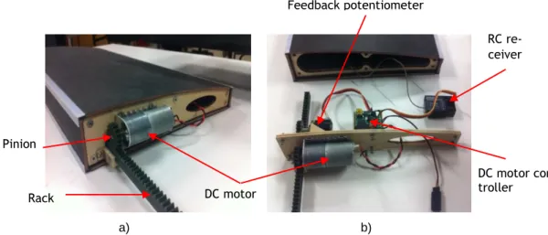
Felício et. al. [29] developed and validated a variable-span morphing wing through graphical CAD/CAM tools intended to be fitted to a small UAV prototype (named Olharapo). The wing is built in composite materials and is made of two parts. The inboard part is fixed to the fuselage and uses a monocoque skin construction. The outboard part slides inside the inboard part to change the span of the wing and uses a typical structure made of spar, ribs and thin skin. An electro-mechanical actuation mechanism is developed using an aluminium rack and pinion sys-tem driven by two servomotors placed at centre of the wings. Figure 2.11 shows the CAD model and a detail of the wing’s variable span system.
a) b)
Figure 2.11: Wing central bay: (a) CAD model and (b) wing prototype. 1) servo motors supporting board; 2) board linkage; 3) wing-fuselage lug; and 4) upper board and actuation bay [29]
2.3.
Various combined in-plane morphing capabilities
Alemayehu et. al. [30] designed and constructed a wing-box mechanism capable of changing wing span, chord and sweep by means of actuators and servos, and an electric motor powering screws (which can be seen at Figure 2.12 b) highlighted by red arrows). The mechanisms used to accomplish all these intended motions can be seen in Figure 2.12 and Figure 2.13.
a) b)
Figure 2.12: Span and chord setup (The red arrows point to the three power screws) [30]
a) b)
Figure 2.13: Wing-box mechanism a) sweep mechanism after construction and b) CAD drawing of wing-box with wings [30]
NextGen Aeronautics [31] developed an UAV, called the MFX-1 and referred to as the Bat-Wing, with a wing that could undergo significant sweep changes during flight. An electric motor deformed an endoskeleton wing-box structure that was covered with an elastomeric skin with out-of-plane stiffeners. Later the second-generation MFX-2 is a twin-jet, 135kg (300lb) UAV than can be switched between remote and autonomous control in flight. An articulating struc-ture and flexible skin enables a 40% change in wing area, 73% change in span and 177% change in aspect ratio, says NextGen. Unlike conventional variable-geometry wings, morphing allows area and sweep to be varied independently to optimise the configuration for multiple flight regimes.
Vale [32] developed a concept that integrates aerofoil camber change with a telescopic span variation concept. The telescopic wing is made of two elements, one that slides inside the other by means of a pull-pull cable and pulleys. The inner and outer aerofoil sections must always be deformed in a similar fashion to allow the telescopic motion to occur. The wing skin is supported by carbon fibre ribs whose contour thickness is tailored to allow shape changes between a symmetrical aerofoil and a cambered aerofoil. Between these ribs, the skin is made of balsa wood and a circular spar at the leading edge provides bending stiffness and strength. Rib de-formation is achieved by rotating screws actuated by small electrical DC motors that make the open trailing edge upper skin slide chordwise in the opposite direction to the lower skin. The aerofoil mechanism of the inner rib is placed inside the wing and that of the outer rib is placed outside the wing.
Gamboa et. al. [33] designed a morphing wing concept for a small experimental unmanned aerial vehicle to improve the vehicle’s performance over its intended speed range. The morph-ing concept is based on changes in wmorph-ing-planform shape and wmorph-ing-section shape achieved by extending spars and telescopic ribs. Variable span, variable chord and variable airfoil shape are the geometric parameters that can be changed. The concept presented does not use adaptive materials; it uses an adaptive internal structure built with conventional materials that are cov-ered with a flexible skin for the aerodynamic shape. Unlike the NextGen bat wing, which has a sweep/chord variation coupling that makes its flexible skin withstand in-plane deformation without altering the airfoil thickness, this concept changes the thickness by out-of-plane actu-ation on the skin. The proposed mechanism tries to produce both chord and span morphing, while allowing changes in the wing airfoil, either by simply scaling the wing airfoil according to the new chord or by actually changing the complete geometry of the airfoil. It consists of a telescopic rib that is actuated by a rotational device that drives screws, causing displacement on the outer skin of the wing section. The amount of displacement in each station of the rib is determined by the screw pitch and the allowable number of rotations that the screw can take at that station. The shape of the airfoil (chord length and thickness distribution along the chord) must therefore be known previously to the assembly of the mechanism, and this is why the optimization process is needed before the design of the morphing mechanism is completed.
2.4.
Sweep morphing
Marmier and Wereley [34] built and tested in a wind tunnel a variable-sweep UAV. A pair of antagonistic inflatable bellow actuators were embedded in a cylindrical polyvinyl chloride fu-selage and controlled by solenoid valves that allowed wing sweep to vary between 0 and 45 degrees. Slide rods guaranteed a smooth translation.
Neal et. al. [35] provided a sweeping mechanism for their shape-morphing UAV that was actuated by means of two electromechanical, lead-screw actuators via a three-bar linkage. Neal et al. also implemented a variable-geometry tail and increased the structural strength.
Mattioni et. al. [36] investigated a variable-sweep wing concept based on bi-stable compo-site spars. The wing-box in their design consisted of two spars with an interconnected truss-rib structure. Each spar had a significant transverse curvature, which increased the bending stiff-ness and also allowed the spar to behave like an elastic hinge under high drag loads. The design could eliminate hinges and mechanisms, but could suffer from fatigue. No skin was included and adding a skin could interfere with the snapping motion.
2.5.
Folding wings
The best-known UAV that performs dihedral and gull variations is the Lockheed Martin z-wing UAV [37] that performs a foldable movement of the z-wing where the span length, aspect ratio, and effective sweep angle may be varied where the span length, aspect ratio, and effec-tive sweep angle may be changed (Figure 2.14). The folding wing design incorporates hinged
joints at two span-wise stations enabling rigid body motion of four primary wing sections. Two approaches to fold the wing were investigated: a thermo-polymer actuator driving a helical spline gear or electro-mechanical rotary actuators. However, the helical spline approach was high risk and hence electrical actuators were used. A morphing UAV aircraft was successfully flight tested.
Figure 2.14: Progressive foldable wing of Lockheed Martin’s concept [37]
A similar prototype was built by Subbarao et. al. [38] which consisted on a mechanism to continuously morph a wing from a lower aspect ratio to higher and to further extremities of a gull-configuration and an inverted gull-configuration with a sliding extendable wing portion with rack and pinion and dc motor mechanism. The mechanism comprises of a linear actuator for the extension of the wing and the servo motors to obtain the gull and inverted gull config-urations.
2.6.
Wing-box structural analysis
Before starting the structural analysis and, mostly, the parametric study, previous publica-tions and researchers of similar projects have been consulted in order to take the best approach to systems developed in a CAD/CAM tool. After the parametric study, numerical computation was used to interpolate results.
Santos et. al. [39] performed the structural design of a composite variable-span morphing wing intended to be installed on a small UAV to provide high flight efficiency in an extended operational speed range, relative to a conventional fixed wing, by symmetrically adjusting the wing span to the flight speed. The focus was on three distinct parts: first, structural layout definition according to the morphing concept constraints and the materials used; second, de-sign for static loads using the finite element method (FEM) where strength, stiffness and weight are key design parameters; and third, experimental testing of a prototype of the wing. Results evidence that the design has good stiffness and strength characteristics and that the numerical predictions correlate well with the experimental tests.
Gamboa et. al. [40] lead a study concentrated on the flutter critical speed estimation be-cause of the effects arising due to the interface between fixed and moving wing parts. Although the former objective is not related with the current study of this work a modal analysis made with ANSYS Structural APDL (Ansys Parametric Design Language) for obtaining mode shapes and natural frequencies can be helpful for the use of the same software and future work. The critical flutter speed was computed using the typical section in aeroelasticity with unsteady
linearized potential theory together with the three-dimensional lifting surface strip theory ap-proximation for lifting surfaces with high aspect ratio. The flutter analysis allowed to conclude that the wing can fly safely within the intended speed envelope because the critical flutter condition is well above the maximum flight speed.
3. Preliminary design
The work in this chapter was not performed by the author of this dissertation alone but also by the different working groups of the CHANGE project partners. The UBI group had a big con-tribution of the work described in this chapter with the author´s collaboration. The structural concept and actuation mechanism were developed by others within this UBI group.
As decided by all partners within the CHANGE project, it is important that the various wing components/mechanisms of the wing should be independent. This approach can facilitate the development of each required mechanism as well as making the integration of all parts easier. According to the shape changes required, the wing cross section is divided into three parts: leading and trailing edge surfaces, and wing-box. Each part contains its own actuation system within its bounds, such that the telescopic motion mechanism is placed inside de wing-box without restrictions.
3.1.
Telescopic wing concept
3.1.1. Design loads
As specified in EASA’s3 Certification Specifications for Very Light Aeroplanes CS-VLA [41] the
design loads are estimated using V-n diagrams which allow to obtain the symmetrical load factor envelope for any given wing configuration as a function of speed.
All wing configurations have a mean chord of 0.6 m and it is assumed that the maximum and minimum manoeuvre load factors in any wing configuration are +3 and -1.5, respectively. It is also assumed that the cruise speed for the fully extended wing is the defined take-off speed
and that the minimum lift coefficient (maximum negative value of CL) is half the maximum lift
coefficient. The wing aerodynamic data used to compute the load factors is presented in Ta-ble 3.1. The calculations made to obtain the n-V diagrams involve two separate diagrams, of which the first is composed. These two diagrams (the manoeuvre and the gust diagrams) are added together to form the final diagram where the most critical segments from both diagrams prevail, limited by the stall load factor. Usually, for non-passenger aircraft, it is not considered
the design speed for maximum gust intensity, VB, so only VC, VD and VS which are cruise speed,
design dive speed and stall speed, respectively, were considered along with the respective wing data values obtained from XFOIL (such as the maximum lift coefficient, lift-curve slope, wing area, design speed, stall speed, etc.).
The combined V-n diagrams obtained are superimposed in Figure 3.1. It is seen that, for the fully extended wing, the critical envelope takes place for the loitering phase. The high-speed envelope shows higher speeds and load factors than predicted and must be considered in the
wing’s structural sizing. It can also be noticed that the critical envelope, at all flight phases, is the gust envelope.
Table 3.1: Required data to compute the V-n diagrams
Wing
configu-ration Wing area
[m2] Maximum lift coefficient (CL max) Minimum lift coefficient (CL min) Lift curve slope [rad-1] Cruise speed [km/h] Take-off 2.4 1.42 -0.71 4.297 76 Loiter 2.4 1.56 -0.78 4.167 76 High-speed 1.8 1.38 -0.69 3.82 110 Landing 2.4 1.53 -0.765 4.167 76
Figure 3.1: Combined V-n diagrams
For the loiter and high speed V-n diagrams the positive limit load points are extracted, considering a low speed, high load factor and high angle of attack case and a high speed, high load factor and low angle of attack case. As said earlier, the gust load factors must be computed as described in EASA CS-23 certification specifications from pages 1-C-2 to 1-C-5. From the
values of speed and load factor, the wing’s lift coefficient (CL) is calculated as follows in
equa-tion 3.1: 𝐶𝐿= 𝑚 𝑔 𝑛 1 2 𝜌 𝑉2 𝑆 (3.1) Where:
-4,0
-3,0
-2,0
-1,0
0,0
1,0
2,0
3,0
4,0
5,0
6,0
0
25
50
75
100
125
150
Load
fac
to
r,
n
Speed, V [km/h]
Take-off Loiter High-speed Landingg = Acceleration due to gravity [m/s2]
n = Load factor
ρ = Density of air at the altitude considered [kg/m3]
V = Aircraft equivalent speed [m/s] S = Wing area [m2]
Then, from the lift and drag coefficient curves and the pitching moment coefficients ob-tained from the XFOIL analysis, the corresponding angle of attack and drag coefficient are acquired. Finally, lift, drag and pitching moment are calculated for the given speed and wing area as follows in equations 3.2, 3.3 and 3.4:
𝐿 = 1
2 𝜌 𝑉
2 𝑆 𝐶
𝐿 , 𝑁 (3.2)
Where:
ρ, V, and S are referred to in equation (3.1) CL = Wing Lift coefficient
𝐷 = 𝐶𝐿
𝐿
𝐶𝐷
, 𝑁 (3.3)
L and CL are referred to in equation (3.2)
CD = Wing Drag coefficient
𝑀 = 1
2 𝜌 𝑉
2 𝑆 𝐶
𝑚 0.6 , 𝑁𝑚 (3.4)
Where:
ρ, V, and S are referred to in equation (3.1) Cm = pitching moment coefficient
All these values are summarized in Table 3.2, next.
Due to the negative load factors being much lower than the positive ones, those will not be considered for the wing-box sizing.
Since lift and drag are perpendicular and parallel, respectively, to the free stream direction, they are rotated by the angle of attack to give vertical and horizontal components, perpendic-ular and parallel to the wing chord line, respectively. The loads used to size the wing-box are shown in Table 3.3.
![Figure 1.1: Spider plot comparing performance of the base-design Firebee, the morphing aerofoil Firebee and the morphing planform Firebee [6]](https://thumb-eu.123doks.com/thumbv2/123dok_br/19170216.940876/24.892.230.624.369.662/comparing-performance-firebee-morphing-aerofoil-firebee-morphing-planform.webp)
![Figure 1.2: Spider plot comparison of NextGen’s fixed and morphing wings aircraft [7]](https://thumb-eu.123doks.com/thumbv2/123dok_br/19170216.940876/25.892.306.637.117.352/figure-spider-comparison-nextgen-fixed-morphing-wings-aircraft.webp)