AbstrAct: The main goal of this paper is to analyze if it is feasible to employ a trained shape memory alloy wire as a linear actuator to modify the camber of a morphing wing rib. In order to achieve this purpose, a morphing rib with a compliant trailing edge was proposed, developed, and subjected to structural analyses to ensure its lexibility. After the rib coniguration was set, it was manufactured by a 3-D printer. The NiTi wire used as actuator was trained by a thermomechanical procedure based on a cycling process with a constant load application to present the two-way shape memory effect. In that way, the wire presents a determined length at its low-temperature phase and a shorter one at its high-temperature phase. Since the wire contraction and the torque applied by it are two crucial factors to deine the camber curvature, it was decided to study two different wire lengths: 103.5 and 152.1 mm. The aerodynamic performance of the morphing cambered airfoils was studied using XFOIL software and compared to that of conventional airfoils with single hinged lap. The results show that both morphing airfoils present better aerodynamic performance for small angles of attack.
Keywords: NiTi, Morphing airfoil, Compliant mechanisms, Shape memory alloy actuator, Two-way shape memory effect.
Construction of a Morphing Wing Rib
Actuated by a NiTi Wire
Thais Campos de Almeida1, Osmar de Sousa Santos1, Jorge Otubo1
INTRODUCTION
In aeronautics, “shape morphing” has been used to identify those aircrat that undergo certain geometrical changes to enhance or adapt to their mission proiles (Sola et al. 2010). here is not an exact deinition of this kind of structures; however, there is a general agreement that the conventional hinged control surfaces or high lit devices, such as laps or slats that provide discrete geometry changes, cannot be considered as “morphing” (Sola et al. 2010). herefore, it can be concluded that a smooth modiication in the geometry, when it is required, certainly characterizes a morphing structure. Morphing aircrat structures can signiicantly enhance air vehicle performance (Kota et al. 2003); for example, a conventional hinged mechanism will create discontinuities over the wing surface leading to earlier airlow separation and drag increase (Shili et al. 2008). A wing with variable camber would provide an increase in aerodynamic efficiency (lift-to-drag ratio) resulting in reduction of fuel consumption and structural weight (Campanile and Sachau 2000). Due to these beneits, researches to design a morphing wing capable of changing the airfoil camber continuously is the most investigated approach of this technique (Sola et al. 2010). Parallel to this, it is a well known fact that one of the most concerns in aeronautical industry is the reduction of costs that can be achieved by several diferent ways including reducing drag, weight, fuel consumption, and maintenance. As already stated, a morphing structure has the ability to reduce the drag and, if combined with a light in weight and reliable actuator, may reduce the total weight and, consequently, fuel consumption as well as the need for maintenance. Knowing this fact, the Boeing Company has been actively developing a robust solid state active hinge pin actuator (AHPA) using shape memory alloy (SMA)
1.Instituto Tecnológico de Aeronáutica – Departamento de Materiais e Processos – Divisão de Engenharia Mecânica – São José dos Campos/SP – Brazil. Author for correspondence: Thais Campos de Almeida | Instituto Tecnológico de Aeronáutica – Departamento de Materiais e Processos – Divisão de Engenharia Mecânica | Praça Mal. Eduardo Gomes, 50 – Vila das Acácias | CEP: 12.228-900 – Sao José dos Campos/SP – Brazil | Email: [email protected]
that can reliably apply high torque and angular displacement with a low space, weight and power burden. hey compared the SMA actuator designed with equivalent actuators, such as a servo motor (torque of 66 in × lbs and weight of 25 lbs), as well as a reduction gear (torque of 190in × lbs and weight of 16 lbs), and found that AHPA can provide comparable torque (150in × lbs), saving considerable weight (1 lbs) (Mabe et al. 2008).
herefore, since the both topics addressed are promising in aeronautical industry, it is essential to further explore them. Because of that, the main goal of this study was to verify the feasibility of developing a morphing rib actuated by SMA wires. Next sections bring a summary of researches about those concepts in order to provide a better understanding of this research.
Airfoil with VAriAble cAmber Using compliAnt mechAnisms
A compliant mechanism is a class of mechanisms that relies on elastic deformation of its constituent elements to transmit motion and/or force (Kota et al. 2003). It is not only lexible to deform, but also has enough stifness to withstand external loads (Shili et al. 2008). he primary advantages of compliant mechanisms are that fewer parts, fewer assembly process, and no lubrication are needed. he disadvantages include fatigue problems and the fact that some of the input energy is stored as elastic work in the mechanism, thereby reducing eiciency (Luo et al. 2005). Although there are disadvantages, the advantages of a compliant wing may overcome them depending on the compliant mechanism designed and, as it can be seen in the next examples, there are several diferent conigurations already developed.
In 1999, Saggere and Kota designed a procedure for shape control that was extended to shape changes at the leading and trailing edges of an airfoil. he method was able to design compliant mechanisms similar to cobwebs making the least square errors between the shape-changed curve and the target curve as the objective function for optimization. he compliant mechanisms efect the desired shape changes in the airfoil by transforming the input torque (or rotation) into controlled displacements of a inite number of discrete points on the airfoil contour. he input actuator could be any torque-generating source (with adequate power for the task) such as a conventional electrical servomotor or a smart material-based torque tube (Saggere and Kota 1999).
In 2000, Campanile and Sachau studied a structure called belt-rib, which would replace the classical rib. he belt-rib structural frame consists in a closed shell (belt) reinforced by
in-plane stifeners (spokes) (Campanile and Sachau 2000). he spokes were connected to the belt by lexible hinges which provided rotational freedom at the joints. he shape behavior of a belt-rib is deined by the coniguration of the spokes and the bending lexibility of the belt. Campanile and Sachau also thought about the type of actuation that a belt-rib could receive. For example, if the actuator elements were SMA wires, a truss coniguration could be adopted in order to provide a range of deformation downwards and upwards.
Another work in which Kota was involved, this time, in partnership with Hetrick (Kota et al. 2003), was a compliant trailing edge that could change from 0° to +15° based on the deformation of beams connecting upper and lower surfaces. his study resulted in a patent (Kota and Hetrick 2006).
Shili et al. (2008) developed a systematic approach to design compliant structures to carry out required shape changes under distributed pressure loads. he method uses MATLAB and ANSYS to optimize the distributed compliant mechanisms by way of the ground approach and genetic algorithm (GA) to remove the elements possessive of very low stresses. he resultant structure could make its shape change from 0° to +9.3° (Shili et al. 2008).
Based on the research of Kota and Hetrick, Medeiros (2011) designed, constructed and tested in a wind tunnel a wing composed of ribs with a compliant trailing edge. he trailing edge was made using a 3-D printer which used ABS as raw material.
Although made by two diferent authors, the ribs presented by Campanile and Hetrick have an aspect in common: the presence of inclined beams connecting upper and lower surfaces. Furthermore, the study of Medeiros showed that this solution provides favorable results and could be a promising concept for a morphing wing. Because of that, the rib coniguration designed in this study was irstly based on the trailing edge already built by Medeiros (2011).
shApe memory Alloy ActUAtion
SMAs are a type of smart materials that are characterized by the shape memory efect (SME). he SME is a unique property of certain alloys exhibiting martensitic transformations (Otsuka and Wayman 1998). Even though the alloy is deformed in the low-temperature phase, it recovers its original shape by the reverse transformation upon heating to a critical temperature called the reverse transformation temperature (Otsuka and Wayman 1998). he low-temperature phase, martensite, is a simple monoclinic arrangement of 24 variants, depending on the local stress ield, and can appear as twinned or detwinned (Ko et al. 2014), whereas the high-temperature phase, austenite, consists of a body-centered cubic structure. When a SMA is heated, it begins to transform from martensite into austenite phase in a process called martensitic transformation. The austenite start temperature (As) is the temperature in which this transformation starts, and the austenite inish temperature (Af) is the temperature in which this transformation is complete. Once a SMA is heated beyond As, it begins to contract and transform into the austenite structure, i.e. to recover in its original form. During the cooling process, the transformation starts to revert to the martensite phase at the martensite start temperature (Ms) and is complete when it reaches the martensite inish temperature (Mf) (Jani et al. 2014).
he two-way shape memory efect (TWSME) is a property that a SMA can acquire ater certain thermomechanical training. In this efect, the alloy can remember its shapes in both high and low temperature without the need of an external stress to impose its low temperature format.
SMA has already been used in aeronautical industry as actuator in an active serrated aerodynamic device known as a variable geometry chevron (VGC) capable of reducing noise during take-of (Jani et al. 2014). Indeed, the use of SMA as actuator is promising, since it would eliminate the need for hydraulics and electrical motors (Mabe et al. 2008). An actuator can be reduced to a single SMA wire providing simplicity, compactness, and safety (Dasgupta 2013). Furthermore, the stroke and force required for a particular actuator can be easily achieved by using the right SMA (Dasgupta 2013), since SMA properties can have a wide variation according to the chemical compositions and heat treatments to which the alloy has been subjected (Barbarino et al. 2014). here are three major types of SMA systems at present, namely Cu-based (mainly CuAlNi and CuZnAl), NiTi-based, and Fe-based (e.g. FeMnSi, FeNiC, and FeNiCoTi) (Barbarino et al. 2014). NiTi-based shape memory alloys have, to date, provided the best combination of properties
for most commercial applications (Dasgupta 2013). Moreover, it has two great advantages: high actuation stress (up to 500 MPa) (Sun et al. 2012) and large recoverable strain (about 8%) (Barbarino et al. 2014). Due to their beneits, there are some studies about the use of SMAs in aeronautical industry, more speciically, as an actuator capable of changing the camber of an airfoil, producing a morphing wing, as it can be seen in the next two examples.
Strelec et al. (2003) used two-way SMA wires as linear actuators attached to certain points inside a shell, whose geometry was an airfoil, made of ABS. When heated, the SMA wires contracted, cambering the airfoil and, when they had been cooled, the airfoil returned to its previous shape. Experimental results proved that there was a trailing edge deflection of 6.0 mm (Strelec et al. 2003).
Ko et al. (2014) constructed a wing with a morphing lap using SMA spring as actuator. Unlike from a compliant trailing edge, in their study, the airfoil camber is modiied by means of multiple elements joined together in a way that allowed relative rotations of adjacent elements causing a smooth contour. Results show that a gain of 72% in lit-to-drag ratio can be achieved when compared with a conventional hinged lap.
Although there are several shapes that a SMA can acquire in order to be used as actuator, such as torque tubes, strips, and springs, in this work, it was chosen to use a trained NiTi wire working as a linear actuator due to its simplicity and space saving.
METHODOLOGY
rib configUrAtion
Relevant Factors
to camber it. h e aerodynamic analysis is equally important, once it will inform if there was an improvement in the quality of the air l ow around the airfoil.
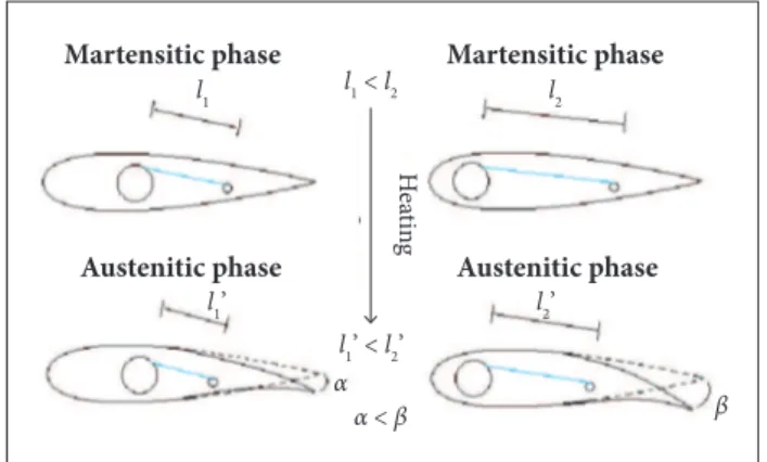
Another analysis that should be performed concerns the position of the SMA actuator, since the wire length will be responsible for the presence or absence of camber. While in martensitic state, the wire will be in its longest length: the rib will not be cambered. When heated, the wire will shrink (austenitic state), cambering the airfoil. h e resulted camber, certainly, will depend on the amount of the wire contraction. Figure 1 schematically shows such ef ect (the blue line represents the SMA wire while the circles represent the positions where the wire extremities will be fastened to the rib).
At er the coni guration is set, the rib will be manufactured using a 3-D printer.
For the subsequent structural analyses, it was created a 3-D mesh using octree tetrahedron elements of linear type, with 1 mm size and 0.3 mm absolute sag. h e rib will be manufactured by a 3-D printer that uses poly-lactic acid (PLA) as raw material. Table 1 shows the mechanical properties of PLA (Mathew et al. 2005) employed to perform the structural analyses.
It is important to note that, at this point, it was not known the quantity of load that the NiTi wire would be capable of af ording or its percentage of contraction. To observe the l exibility of the structure, a load of 5 N (randomly chosen value) was applied in point B directed to point A. h is structural analysis showed that this i rst design was rigid: the trailing edge del ected only 2.77 mm (1.8°).
Due to this fact, L was expanded to 50% of the total chord length, creating the second coni guration. Its structural analysis proved that this rib is more l exible: the trailing edge del ected 5.5 mm (2.5°). Moreover, both coni gurations showed that there is a maximum stress concentration located at the upper region of the i rst beam. h is fact was already studied in the Medeiros’ work (2011). The maximum stress of the first coni guration was 14.5 MPa while for the second one it was 11.6 MPa, an improvement of 20%. h is fact induced a study about the i rst beam slope. It was constructed a third design with β equal to 45.6°. A fourth configuration with a greater inclination (β < 33.7°) would decrease the rigidity of the rib, so this idea was discarded.
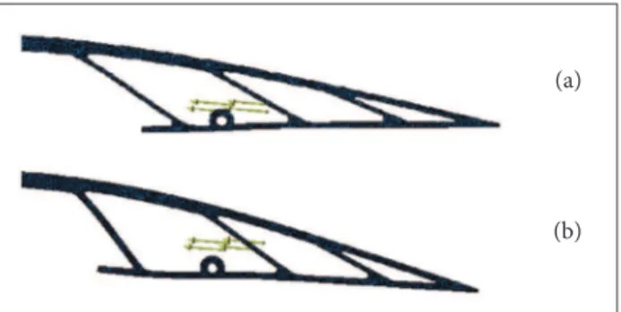
h e structural analysis of the third coni guration showed that the maximum stress was 14.8 MPa and located at the same point. h erefore, there was a worsening of 27.6% when compared with the second coni guration. Furthermore, the third coni guration, when loaded by 10 N, presented an abrupt change of curvature at lower surface around the i rst beam (Fig. 3b), which may cause a detachment of the air l ow. Because
Martensitic phase Martensitic phase
Austenitic phase Austenitic phase
He
at
in
g
l1 < l2
α < β α
β l1’ < l2’
l2’
l1’
l2 l1
Length
B β A
C
F igure 1. Schema showing the effect of the wire length
(blue) in airfoil camber. l1 and l2 refer to the wire length.
Design Process
h e rib i nal coni guration is presented in Fig. 2. h e airfoil used was the NACA0012 because it is simpler to build and it is symmetric (it has no camber): the lit produced when in zero angle of attack is null. It has trusses near the leading edge to provide rigidity to this region. h e spar (an aluminum tube) is attached to the second hole (A), while the third hole was made for saving material. h e fourth hole (B ) has a smaller diameter in order to be attached to a light in weight aluminum tube that will work as stringer.
In the i rst coni guration, the l exible trailing edge length (L ) covered 35% of the total chord, also the i rst beam had a slope (β) of 33.7°. h e SMA wire would be fasten to A and B tubes. h e idea is to provide the highest possible torque and wire length, thus the wire should be attached to the positions indicated by the red dots in Fig. 2.
young’s modulus 3.6 GPa
poisson ratio 0.36
density 12,600 kg/m3
yield strength 49.6 MPa
Fi gure 2. Final coni guration.
of these facts, it was decided to maintain the studies using the second coniguration.
Another interesting investigation concerns the position of the tubes A and B since it will afect the trailing edge delection. On the one hand, it is better to maintain point B far from the trailing edge in order to be also far from the chord line providing a greater torque. On the other hand, it is a good idea to change point A
towards a position nearer the leading edge because it would enlarge total distance between these points, increasing wire size. hus, it was created a new position corresponding to point C in Fig. 2.
It is important to note that the position of tube/point A or C
could be modiied to achieve a wire length/torque suicient to produce a required camber, or, more speciically, a required lit and drag. In other words, A, B, and C positions could be rearranged in order to the wing be able to adapt to diferent lying conditions. In this study, both conigurations will be studied: the one produced by a wire size of A – B and the other by a wire size of C – B.
of martensite twins; (II) the reorientation of martensite variants causes a slight stress-drop followed by a stress-plateau until about 6% strain; (III) the elastic deformation of fully reoriented martensite causes a further increase in the stress with the increasing deformation; and (IV) a inal plastic deformation of the reoriented martensite with further deformation leads to rupture (Liu et al. 1998).
niti wire trAining
he wire was trained in order to acquire the TWSME. here are several methods of training for TWSME. In this study, it was chosen an already known process based on constant load application. his method has four steps, as following:
1. he wire is attached to a platform in a room where the temperature is below Mf.
2. he wire is deformed (extended) by a tensile load equal to the stress-plateau.
3. he wire is heated for 20 s by Joule efect until it achieves a temperature above Af in order to recover its length.
4. he power is switched of, and the wire is cooled down to room temperature (below Mf) by natural convection, being deformed by the load again.
he thermal cycle, composed of steps 3 and 4, is repeated several times until it reaches stable results. According to Hebda and White (1995), ater 2,000 cycles, Ni-55at%.Ti SMA wires achieved the stabilization of TWSME behavior. To ensure the TWSME behavior, the thermal cycle was repeated about 4,600 times. Figure 4 shows a scheme enlightening the training procedure (steps 3 and 4).
Heating
Cooling
Martensitic phase Austenitic phase
m SMA wire
T > Af SMA wire
T > Mf
m
Figure 3. Trailing edge detail for a structural analysis with a
load of 10 N for: (a) Second and (b) Third conigurations.
wire mAnUfActUring process
he starting material was a NiTi ingot melted by vacuum induction melting (VIM) with controlled chemical composition. The ingot was hot-formed and then wire drawn to a wire diameter of 0.4 mm at the ITASMART facilities.
tensile test
he mechanical properties of the NiTi alloy manufactured were investigated by an Instron 5500R tensile testing machine. he specimen tested was a wire with a diameter of 2.058 mm. he test was performed using a strain rate of 2 m/min and a load cell of 30 kN until the specimen rupture.
he behavior of a twinned martensitic NiTi SMA under tension follows four basic steps: (I) at the beginning of deformation, it occurs a monotonic increase in the stress with increasing strain amplitude until about 1% strain due to the elastic accommodation
Figure 4. Scheme showing the thermal cycle responsible for
inducing the TWSME behavior. m: mass; T: temperature.
(a)
(b)
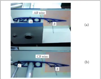
visualization of the new airfoil after actuation, as it can be seen in Fig. 5. The airfoil chord is 250 mm, which results in a wire size A – B of 103.5 mm (Fig. 5a) or C – B of 152.1 mm (Fig. 5b). The wires were cut and then connected to the tubes by screw and washers.
he electrical current lows through tubes A and B (AB
coniguration) or C and B (CB coniguration), heating the SMA wire by Joule efect.
Furthermore, the aerodynamic characteristics of the morphing airfoil will be compared with the conventional hinged-lap NACA0012 airfoil delected by the same amount of the morphing rib trailing edge.
AeroelAstic AnAlysis
Due to the rib lexibility, the trailing edge delection caused by the wire contraction may experience a reduction when subjected to aerodynamic loading. he real delection may be calculated by performing the sum of moments at the articulation point, which results in Eq. 1:
Figure 5. Rib attached to the constructed device along with
(a) AB and (b) CB wires.
AerodynAmic AnAlysis
Ater heating the SMA wire, the rib will camber, creating a new airfoil. he points of the upper and lower surfaces of this generated airfoil are detected by drawing the contours in the millimeter paper (Fig. 5). hen, the aerodynamic characteristics of these new airfoils are studied using the XFOIL sotware. he analysis performed was viscous with Reynolds number equal to 300,000, which is included in the range of large model airplanes (Lissaman 1983). he angle of attack varied from −10° to 14.5° at 0.5° intervals. he results will be analyzed by two primary factors employed to judge the quality of an airfoil (Anderson 1991), as follows:
• he lit-to-drag ratio (L/D or cl/cd) since an eicient airfoil produces lift with a minimum of drag. An increased lit-to-drag ratio promises a longer operation distance and elongated light time with the same amount of fuel under the same light conditions (Ko et al. 2014).
• he maximum lit coeicient (cl,max), which determines the stalling speed of an airfoil. Increasing it, it will obtain lower stalling speeds or higher payload weights at the same speed (Anderson 1991).
where:
H is the aerodynamic moment of the lexible surface; τWire is the torque applied by the wire; τStructure is the torque resisted by the structure.
The aerodynamic moment at the articulation point is calculated by Eq. 2:
where:
q is the dynamic pressure; cf is the lap chord; Ch is the articulation coeicient moment.
he articulation coeicient moment can be estimated by using the function fmom inside de oper menu in XFOIL. However, as it can be observed from Eq. 2, H is a function of the wingspan, which is not known yet. Moreover, it also depends on the angle of attack. Just for the sake of curiosity, it will be studied the case for an angle of attack null and a wing span of 0.455 m. he other parameters employed are displayed in Table 2.
reynolds number (Re) 300,000
mach (M) 0.051
Velocity (V) 17.46 m/s
Air density (ρ) 1.23 kg/m3
cf 0.125 m
Table 2. Parameters used for the calculation of the
articulation moment.
(1)
(2) (a)
(b)
B
B A
C
AB wire
CB wire
since the last one will be considered null, this relation may be represented by Eq. 3:
RESULTS
wire mAnUfActUring process
Table 3 shows the chemical composition of the NiTi wire in at %.
Table 4 presents the martensite transformation temperatures (MTT) of the NiTi alloy. They were measured using a differential scanning calorimetry equipment (DSC404C Pegasus - NETZSCH) located at the ITASMART facilities. As it can be noted, every characteristic temperature is above room temperature, i.e. the alloy is in the martensite phase in room temperature.
Flexible articulation
δ Kδ
4 0 3 5 3 0 2 5 2 0 1 5 1 0 5
IV III
II
I
0 1 0 0 3 0 0 5 0 0 7 0 0 9 0 0
Strain [%]
S
tr
ess [M
p
a]
herefore, H may be represented by Eq. 4:
where: s means span.
τStructure may be estimated using CATIA. Since the rib trailing edge rotates around the articulation point, it may be supposed that the rib lexible region is equivalent to a torsion spring, as shown in Fig. 6.
hus, the articulation torque applied by the trailing edge structure can be calculated using Eq. 5:
Figure 6. Schema showing the equivalence between the
lexible articulation and the torsion spring, where K is the articulation stiffness.
he articulation stifness (Kδ) may be found by the same approach as the one used in the structural analysis. Varying the value of the torque applied by the wire in CATIA, it will be extracted a curve showing the relation between τStructure, which is equal to τWire — in this case, because H is null —, and the trailing edge deflection. This relation must be linear with the slope equal to Kδ as stated in Eq. 5.
Finally, considering that the torque applied by the wire is constant and depends exclusively on its temperature, it can be estimated by using the relation found previously for a null H. In this way, the real delection may be calculated by Eq. 6:
Ms (°c) Mf (°c) As (°c) Af (°c)
53.2 43.1 69.3 84.6
Table 3. NiTi alloy chemical composition.
ni (at%.) ti (at%.) c (at%.) o (at%.)
49.420 50.409 0.060 0.111
Table 4. Martensitic transformation temperatures.
tensile test
he stress-strain curve of the NiTi wire is exhibited in Fig. 7, and, as it can be noted, it presents the characteristic behavior of a twinned martensitic NiTi SMA under tension.
he stress-plateau (region II) of this wire is about 136 MPa. herefore, the strength to which the wire should be subjected in its training is, approximately, 17 N, corresponding to a mass of 1.74 kg. However, as the cycles are reproduced, more defects are introduced in the wire, which generates a new state ater each cycle and changes the stress-plateau to a lower level, modifying the strength required for the training. his is noted due to the change in the wire diameter size and length. As more cycles were reproduced, the wire became thinner and longer. he solution found to solve this problem was to apply less strength
Figure 7. True strain-stress curve of the NiTi alloy.
(3)
(4)
(5)
at each cycle until the wire achieve a stable diameter size, which occurred at a load of 1.32 kg.
trAiling edge deflection
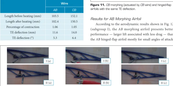
The trailing edge (TE) deflection due to each wire size studied is reported in Table 5. he TE delection can be seen in Fig. 8, where six situations are presented: TE before (a); during (b), and ater actuation (c) for (1) AB wire coniguration or (2)
CB wire coniguration. It is important to note that, ater the actuation, the rib returned its shape to the original one, without the visible presence of permanent deformations.
he morphing cambered airfoils are displayed in Fig. 9. It can be noted that, although there is a great difference between the lengths of the studied wires (about 50%), there is not a great difference between the resulted airfoils. This occurs because AB wire provides more torque since point A
is farther from symmetry line — chord line — (13 mm) than point C (9.266 mm). herefore, although wire size is crucial for the resulted TE delection, the torque applied also plays a fundamental role.
AerodynAmic AnAlysis
he morphing airfoils and their respective hinged-laps NACA0012 are exhibited in Figs. 10 and 11. he hinged-lap coordinates were located in order to better reproduce the
Figure 9. Morphing airfoils derived from NACA0012 after
actuation of AB or CB wire.
Table 5. Results for both conigurations studied.
wire
AB CB
Length before heating (mm) 103.5 152.1
Length ater heating (mm) 102.4 150.5
Percentage of contraction 1.06 1.05
TE delection (mm) 11.6 14.0
TE delection (°) 5.3 6.4
Figure 8. Trailing edge: Before (a), During (b), and After heating (c) for AB (I) or CB (II) wire.
0 .0 8 0 .0 4 0
0.1 0.2 0.3 0.4 0.5 0.6 0.7 0.8 0.9 1
–0.04 –0.08
NACA0012 Morphing AB Morphing CB
0.08 0.04 0
0.1 0.2 0.3 0.4 0.5 0.6 0.7 0.8 0.9 1
–0.04 –0.08
Flap AB
Morphing AB
0.08 0.04 0
0.1 0.2 0.3 0.4 0.5 0.6 0.7 0.8 0.9 1
–0.04 –0.08
Flap CB
Morphing CB morphing airfoil: x is equal to 50% of the chord and y is attached to the upper surface. It is important to note that, in the cases studied, there are not great diferences between the morphing or lapped conigurations. However, these small diferences can have a large impact on aerodynamic coeicients.
Figure 10.AB morphing (actuated by AB wire) and hinged-lap
airfoils with the same TE delection.
Figure 11.CB morphing (actuated by CB wire) and hinged-lap
airfoils with the same TE delection.
I (a) I (b) I (c)
II (a) II (b) II (c)
Results for AB Morphing Airfoil
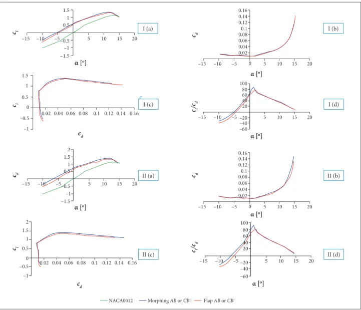
In Fig. 12a, it can be noted that, with the cambering of the airfoil either by the morphing structure or by delecting the lap, the maximum lit coeicient (cl , m a x) increases while the critical angle of attack (αstall) decreases. his property relects the aerodynamic characteristics of the presence of high-lit devices, since as the lap delects downward, the lit curve simply translates to the let because the angle of attack that generates a null lit (αL = 0) becomes more negative as the camber increase (Anderson 1991). Moreover, the cl , m a x produced by the morphing airfoil (c l , m a x= 1.3536), in the studied conditions, is slightly greater (about 2%) than the one produced by the hinged-lap airfoil (cl , m a x = 1.3265). he morphing airfoil has a maximum lit-to-drag ratio of 86.97 at an angle of attack equal to 1.5°, while for the lapped airfoil it is 78.87
Figure 12. Aerodynamic coeficients for (I) AB and (II) CB morphing airfoil: (a) Lift coeficient versus angle of attack; (b) Drag
coeficient versus angle of attack; (c) Drag polar curve; (d) Lift-to-drag ratio versus angle of attack. I (c)
at 2°. Analyzing the condition of maximum lit-to-drag ratio for both airfoils, the morphing airfoil presents a 10.26% gain, with 0.14% increase in lit and 9.18% decrease in drag. Furthermore, the improvement in the efficiency of the morphing airfoil (cl/ c d) occurs until an angle of attack of 1.5°; ater that, both airfoils present similar lit-to-drag ratios.
Results for CB Morphing Airfoil
In accordance with the previous airfoil, the CB morphing presents better performance — larger lit associated with less drag — than the CB hinged-lap airfoil mostly for small angles of attack (Fig. 12, subgroup II). Moreover, the CB morphing presented a slightly greater cl,max (cl,max = 1.3874) than the lapped one
1.5
–1.5 –1
5
0.02 0.04
–15 –10 –5 5 10 15 20
0.06 0.08 0.1 0.12 0.14 0.16
0.02 0.04 0.06 0.08 0.1 0.12 0.14 0.16
1.5
1
0.5
0
2 1.5 1 0.5
–0.5
–1.5 –1 –0.5
–1
1.5 2
1
0.5
0 –0.5
–1
–5 10
–10 15
–15 20
1 0.5
–0.5
α [o]
α [o]
c d
cl
cl
c d
cl
cd
–15 –10 –5 0 5 10 15 20
α [o]
cd
–15 –10 –5 5 10 15 20
α [o]
cl
/cd
–15 –10 –5 5 10 15 20
α [o]
cl
/cd
–15 –10 –5 0
0.02
100 80 60 40 20
–20 –40 –60
0.16 0.14 0.12 0.1 0.08 0.06 0.04 0.02
100 80 60 40 20
–20 –40 –60 0.04 0.06 0.08 0.1 0.12 0.14 0.16
5 10 15 20
α [o]
cd
I (c) I (d)
I (a) I (b)
II (a) II (b)
II (c) II (d)
Figure 13. Linear regression showing the relationship between H and δ.
H = 0.006 δ
δ [o]
H
[Nm
]
0.06
0.05
0.04
0.03
0.02
0.01
0
0 1 2 3 4 5 6 7 8
0.1
δ[o]
τSt
r
u
c
tu
re
[N
m]
0.09
0.08
0.07
0.06
0.05
0.04
0.03
0.02
0.01
0
0 2 4 6 8
τ
Structure = 0.013 δ
τStructure = 0.010 δ AB configuration CB configuration
Figure 14. Linear regression showing the relationship
between τStructure and δ for each wire coniguration.
coniguration delection without
aerodynamic loads τWire (nm)
real delection (with aerodynamic loads)
command eficiency
A B 5.3° 0.053 3.31° 62.5%
C B 6.4° 0.083 4.38° 68.4%
Table 6. Real trailing edge delection for each wire coniguration.
(c
l , m a x = 1.3393), about 3.59% in gain. he C B mor p h i ng airfoil has a maximum lit-to-drag ratio of 91.00 at an angle of attack of 1°, while, for the lapped airfoil, it is 80.34 at 1.5°, which indicates an improvement of 13.26% in maximum lit-to-drag ratio due to a 2.15% increase in lit and a 9.81% decrease in drag. For angles of attack less than 1.5°, the eiciency of the morphing airfoil is higher than that of the hinged-lap one; however, for angles greater than 1.5°, both have similar results.
AeroelAstic AnAlysis
In order to ind the slopes of Eqs. 4 and 5, it was made a linear regression using the method of least squares of the extracted data. The results are represented by lines and the corresponding equation in Figs. 13 and 14.
Using the equations in Fig. 14, τW i r e may be estimated by replacing δ with 5.3° or 6.4° depending on the wire coniguration. Furthermore, using Eq. 6, we have the real delection for each case. Table 6 shows the results.
CONCLUSIONS
Morphing airfoils is a very important topic in aeronautics since they can provide gains in efficiency translated into
longer operation distances and higher payload weights. Moreover, when associated with small, reliable, and lightweight actuator, the system becomes simpler, avoiding the need for electrical or hydraulic motors. Because of these benefits, in this work, it was designed a morphing airfoil with a compliant trailing edge actuated by a SMA wire responsible to deflect it.
The findings suggest that this solution is promising since both morphing airfoils presented better aerodynamic results when compared with the correspondent conventional single hinged-flap airfoil. The A B wire actuation provided a
trailing edge deflection of 5.3° resulting in a gain of 10.26% in maximum lift-to-drag ratio and an increase of 2% in the maximum lift coefficient. The C B wire actuation provided a
the efficiency of b o th morphing airfoils is comparable to the hinged-flap one.
These aerodynamic results do not take into account the rib flexibility. Nevertheless, according to the aeroelastic analysis, under aerodynamic loading, the real trailing edge deflection would be less than that commanded by the SMA wire contraction. Therefore, although a morphing rib presents advantages, if applied in an actual airplane, the project must consider that its trailing edge deflection will experience a reduction.
ACKNOWLEDGEMENTS
The authors wish to thank FAPESP, CNPq Universal (476030/2011-0), CNPq/Casadinho/PROCAD (552199/2011-70) UFCG/UFRJ/ITA, PRO-INFRA (2012, 2013 and 2014), CAPES/ITA 005/2014 for fellowship for one of the authors. hanks are due to Villares Metals S. A., Multialloy Metais Especiais Ltda, Marcenaria Exclusiva Mobile, Rafael Endlich Pimentel, Roberto Gil Annes da Silva and Odair D. Rigo for supporting the ITASMART (ITA Shape Memory Alloys Research and Technology Group).
REFERENCES
Anderson JD (1991) Fundamentals of Aerodynamics. New York: McGraw-Hill. Chapter 4, Incompressible low over airfoils; p. 247-314.
Barbarino S, Flores EIS, Ajaj RM, Dayyani I, Friswell MI (2014) A review on shape memory alloys with applications to morphing aircraft. Smart Mater Struct 23(6):1-19. doi: 10.1088/0964-1726/23/6/063001
Campanile LF, Sachau D (2000) The belt-rib concept: a structronic approach to variable camber. J Intell Mater Syst Struct 11(3):215-224. doi: 10.1106/6H4B-HBW3-VDJ8-NB8A
Dasgupta R (2013) Designing shape memory materials or the future. Metalworld 74-78.
Donadon MV, Iannucci L (2014) A numerical study on smart material selection for lapped and twisted morphing wing conigurations. J Aerosp Technol Manag 6(3):281-290. doi: 10.5028/jatm.v6i3.341
Hebda DA, White SR (1995) Effect of training conditions and extended thermal cycling on nitinol two-way shape memory behavior. Smart Mater Struct 4(4):298-304. doi: 10.1088/0964-1726/4/4/010
Jani JM, Leary M, Subic A, Gibson MA (2014) A review of shape memory alloy research, applications and opportunities. Mater Des 56:1078-1113. doi: 10.1016/j.matdes.2013.11.084
Ko SH, Bae JS, Rho JH (2014) Development of a morphing lap using shape memory alloy actuators: the aerodynamic characteristics of a morphing lap. Smart Mater Struct 23(7):074015. doi: 10.1088/0964-1726/23/7/074015
Kota S, Hetrick J, inventors; Flexys, INC, assignee. 2006 Aug 24. Adaptive compliant wing and rotor system. United States Patent US 20060186269 A1.
Kota S, Hetrick J, Osborn R, Paul D, Pendleton E, Flick P, Tilmann C (2003) Design and application of compliant mechanisms for morphing aircraft structures. Proceedings of the SPIE 5054; San Diego, USA.
Lissaman PBS (1983) Low-Reynolds-number airfoils. Ann Rev Fluid Mechanics 15:223-239.doi: 10.1146/annurev. l.15.010183.001255
Liu Y, Xie Z, Humbeeck JV, Delaey L (1998) Asymmetry of stress– strain curves under tension and compression for NiTi shape memory alloys. Acta Mater 46(12):4325-4338. doi: 10.1016/S1359-6454(98)00112-8
Luo Z, Chen L, Yang J, Zhang Y, Abdel-Malek K (2005) Compliant mechanism design using multi-objective topology optimization scheme of continuum structures. Struct Multidiscip O 30:142-154. doi: 10.1007/s00158-004-0512-y
Mabe JH, Gravatt L, Bushnell G, Gutmark E, DiMicco RG, Harris C (2008) Shape memory alloy actuators for deployable rotor blade aerodynamic devices. Proceedings of the 46th AIAA Aerospace Sciences Meeting and Exhibit; Reno, USA. doi: 10.2514/6.2008-1451
Mathew AP, Oksman K, Sain M (2005) Mechanical properties of
biodegradable composites from poly lactic acid (PLA) and microcrystalline cellulose (MCC). J Appl Polymer Sci 97(5):2014-2025. doi: 10.1002/ app.21779
Medeiros RR (2011) Projeto, construção e testes de um modelo de asa de peril variável. São José dos Campos: Instituto Tecnológico de Aeronáutica.
Otsuka K, Wayman CM (1998) Shape memory materials. Cambridge: Cambridge University Press. Chapter 1, Introduction; p. 1-2.
Saggere L, Kota S (1999) Static shape control of smart structures using compliant mechanisms. AIAA J 37(5): 572-578. doi: 10.2514/2.775
Shili L, Wenjie G, Shujun L (2008) Optimal design of compliant trailing edge for shape changing. Chin J Aeronaut 21(2):187-192.doi: 10.1016/S1000-9361(08)60024-2
Sola AYN, Meguid SA, Tan KT, Yeo WK (2010) Shape morphing of aircraft wing: status and challenges. Mater Des 31(3):1284-1292. doi: 10.1016/j.matdes.2009.09.011
Strelec JK, Lagoudas DC, Khan MA, Yen J (2003) Design and implementation of a shape memory alloy actuated reconigurable airfoil. J Intell Mater Syst Struct 14(4-5):257-273. doi: 10.1177/104538903034687
Sun L, Huang WM, Ding Z, Zhao Y, Wang CC, Purnawali H, Tang C (2012) Stimulus-responsive shape memory materials: a review. Mater Des 33:577-640. doi: 10.1016/j.matdes.2011.04.065

![Figure 13. Linear regression showing the relationship between H and δ. H = 0.006 δδ [o]H[Nm]0.060.050.040.030.020.0100123456 7 8 0.1 δ [ o ]τStructure [Nm]0.090.080.070.060.050.040.030.020.010024 6 8τStructure = 0.013 δτStructure = 0.010 δAB configurat](https://thumb-eu.123doks.com/thumbv2/123dok_br/18889437.424656/10.892.462.807.533.899/figure-linear-regression-relationship-τstructure-τstructure-δτstructure-configurat.webp)
