Synthesis of Cu
xO(x = 1,2)/Amorphous Compounds by Dealloying
and Spontaneous Oxidation Method
Zhifeng Wang, Chunling Qin, Li Liu, Lijuan Wang, Jian Ding, Weimin Zhao*
School of Materials Science and Engineering, Hebei University of Technology, Tianjin 300130, China
Received: August 7, 2012; Revised: August 22, 2013
CuxO(x = 1,2)/amorphous compounds have been successfully synthesized by chemical free dealloying and spontaneous oxidation method. Technological parameters, such as the acid concentration
and dealloying time strongly inluence the crystal type, size and morphology of coppery oxide. The
further study shows that with the increase of HCl concentration, the surface coverage rate of Cu2O
micro-lowers increases and the sizes of Cu2O micro-lowers get bigger. Moreover, it is observed that
cracks are formed on the etched ribbon surface and plentiful Cu2O/CuO particles grow up from these crack walls if the dealloying time extends to long enough. Considering many fascinating properties of Cu2O/CuO particles and the amorphous alloy carrier, potential application ields of these amazing compounds will be developed in future.
Keywords: dealloying, amorphous alloy, Cu2O, CuO, compounds
1. Introduction
Dealloying, which refers to the selective dissolution of one or more components out of an alloy, is superior in the fabrication of nanoporous metals with open pores owing to its high reactivity of some alloying elements and controllability of chemical reactions1. This method has
been successfully adopted in the fabrication of nanoporous noble metals in different alloy systems2-4. Nowadays, some
studies reveal that dealloying method can be extended to the fabrication of metal oxide nanostructures with intricate structural properties. Fascinating nanostructures, such as Cu2O nanocubes1,5, octahedral Fe
3O4 and Mn3O4
nanoparticles6, are successfully produced by dealloying
method.
Cu2O, which is an important p-type semiconductor with a direct band gap of 2.17 eV[7], has been widely studied as a
promising material for applications in gas sensors8, in solar
energy conversion9, as an electrode in lithium ion batteries10,
as a photocatalyst for the degradation of organic pollutants11
and for the decomposition of water into H2 and O2 under visible light irradiation12. CuO is a p-type semiconductor
with narrow band gap of 1.2 eV[13], and is known for
its applications in optical switches, field emitters, gas sensors, high temperature microconductors, Li-ion battery anode materials, and chemical conversion catalysts14,15.
Therefore, Cu2O and CuO particles with different size and morphologies are highly desirable for these applications.
So far, Cu2O and CuO have been prepared by several different methods. In our previous paper, we develop a new approach to produce Cu2O/amorphous compounds by free dealloying Cu-based amorphous alloys and spontaneous oxidation method. In this study, we adjust the technical parameters to improve the Cu2O surface coverage rate and produce CuxO(x = 1,2)/amorphous compounds by using
this method. To our knowledge, amorphous alloys are good carriers for CuxO(x = 1,2) particles, because amorphous alloys exhibit high strength and high toughness. In addition, the CuxO(x = 1,2) particles formed in the amorphous alloy precursor are more easier to be stored or extracted as
compared to traditional chemical method. Meanwhile, the
fabrication process of CuxO(x = 1,2) particles are simpliied in this route. The most important contribution by this work is to produce the amazing compounds with multiple properties
which are hopeful to be applied in broad ields in future.
2. Experimental
Cu-based ingots with nominal compositions of Cu52.5Hf40Al7.5 (at%) were prepared by arc-melting Cu (99.99 mass%), Hf (99.99 mass%), and Al (99.99 mass%) metals in high-purity argon gas atmosphere and using Ti getters. Thin precursor ribbons of Cu-based alloys about 20 µm thick and 2 mm wide were prepared by melt-spinning with a linear velocity of the copper wheel of 40 m/s. The free dealloying was performed by immersing amorphous precursor ribbons (about 20 mm long) into HCl solutions with different concentration and immersing time open to air at room temperature. The dealloyed samples were rinsed in deionized water for three times to remove the residual chemical substances and then dried in a vacuum drying oven. The microstructure and surface morphology of the dealloyed specimens were characterized by X-ray diffraction (XRD, Bruker D8, Cu-Kα radiation) and scanning electron
microscope (SEM, Hitachi S-4800), respectively.
3. Results and Discussion
Figure 1 shows XRD patterns of the dealloyed
Cu-Hf-Al amorphous alloys in 0.5 M HCl solution for 0 h, 8 h,
Figure 1. XRD patterns of dealloyed Cu-Hf-Al amorphous alloys in 0.5 M HCl solution for (a) 0 h, (b) 8 h, (c) 14 h, (d) 20 h.
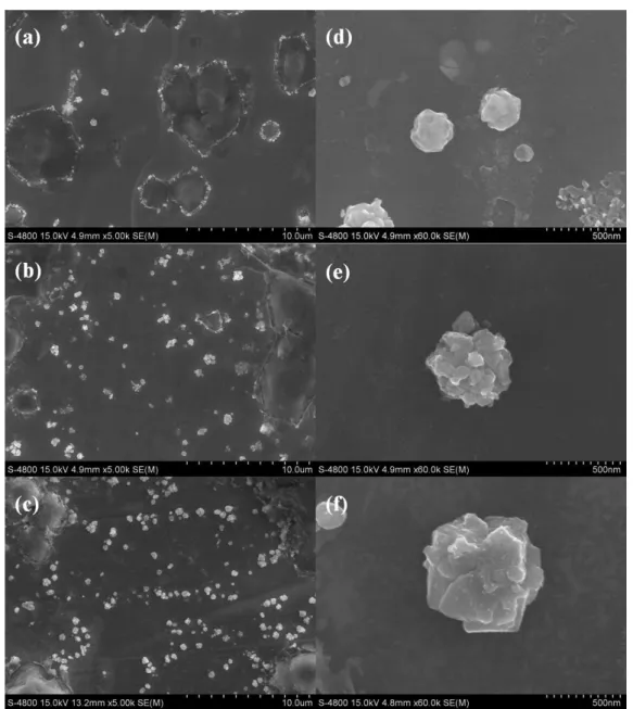
Figure 2. SEM micrographs of Cu2O/amorphous compounds by etching Cu-Hf-Al amorphous alloys in different HCl solution for 8 h
(a) 0.1 M, (b) 0.2 M, (c) 0.4 M. (d) ~ (f) show magniied images of (a) ~ (c), correspondingly.
14 h and 20 h, respectively. The diffraction pattern for the as-spun alloy is broad and has no Bragg peaks, indicating a single homogeneous glassy structure. The XRD patterns of the HCl treated ribbons exhibit broad halo peaks superimposed on sharp crystal peaks. These crystal peaks are match with (111), (200), (220) crystal planes of Cu2O (JCPDS No. 05-0667) and (002), (111), (202) crystal planes
of CuO (JCPDS No.41-0254), respectively. Moreover, the
existence of a broad halo peak reveals that although the surface of the sample is rich in Cu2O and/or CuO, the inner part remains glassy structures. When the dealloying time reaches to 8 h, Cu2O particles are synthesized on the surface of amorphous alloy. The further increasing dealloying time leads to the formation of more oxidation products of CuO instead of Cu2O.
for 8 h. It is observed that Cu2O particles formed in the
amorphous alloy surface exhibit lower morphology when
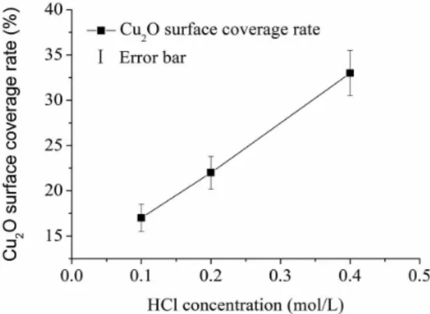
the dealloying time reaches to 8 h. The mean surface coverage rate of Cu2O micro-lowers increases from 17.2% to 33.1% (as shown in Figure 3) with the increase of HCl concentration. The Cu2O coverage rate in this paper has been improved compares with our previous study (13.9%,
0.05 M HCl for 8 h). That is because the increased HCl
concentration promotes the dealloying process, including reaction speed and the reaction extent. As a result, the sizes of Cu2O crystals gradually turn to bigger and Cu2O crystals in regular polyhedral shapes5 cannot retain but grow up to
micro-lowers. On the other hand, SEM micrographs of the Cu-Hf-Al amorphous alloys dealloyed in 0.5 M HCl
solution for different time are shown in Figure 4. When the dealloying time extends from 8 h to 14 h, some cracks are
Figure 3. Cu2O surface coverage rate with different HCl concentration for 8 h open to air at room temperature.
Figure 4. SEM micrographs of CuxO(x = 1,2)/amorphous compounds by etching Cu-Hf-Al amorphous alloys in 0.5 M HCl solution for
formed on the surface of amorphous alloys and deeper cracks are found in the ribbon dealloying for 20 h. Furthermore, it is also observed that plentiful Cu2O/CuO particles grow up from these crack walls. The morphology of Cu2O/CuO
particles generating from crack walls is no longer
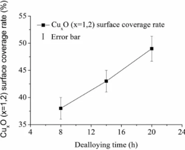
lower-like, but irregular shape. The white nanoparticles denoted by black arrow in Figure 4 (e and f) grow up based on the Cu2O micro-particles, which is a powerful evidence to represent the oxide process from Cu2O to CuO. With the increase of the dealloying time, the mean surface coverage rate of CuxO (x = 1,2) crystals increases gradually (as shown in Figure 5). In addition, more CuO crystals can be detected from both
XRD (Figure 1) and SEM (Figure 4) images.
By dealloying in HCl acidic solutions, the formation of Cu2O and CuO on the ribbon surface is probably through the following process: First, the thin oxidized surface layer of the Cu-Hf-Al alloy is removed in the acidic electrolyte and fresh alloy layer forms on the alloy surface. Subsequent, the constituent element of the alloy are selectively dissolved into
the solutions to form Cu2+ cations along with the other alloy
elements cations1. Meanwhile the oxygen dissolved in the
electrolyte also adsorbs on the fresh alloy surfaces. During the dissolution and adsorption process, Cu2+ cations react
with metallic Cu to form Cu+ through a disproportionation
reaction, these Cu+ cations are unstable and will rapidly
react with the O–O(adsorb) to form Cu2O. As a result, the Cu2O particles are formed through the disproportionation reduction of metallic Cu and Cu2+ accompanied by surface
adsorbed oxygen. If the dealloying time is long enough, Cu2O will further react with adsorbed oxygen in acidic
conditions to form the inal oxidation product CuO.
A formation schematic for CuxO(x = 1,2)/amorphous compounds is illustrated in Figure 6. Once the amorphous ribbon (Figure 6a) is immersed in HCl solution, the dealloying process begins. Because of the metal reactivity Al > Cu > Hf in dilute HCl solution, in principle Al and Cu elements will be selectively dissolved during dealloying process. However, the dissolution rate of Al element is much higher than that of Cu element. As a result, the ribbon retains its main part in dilute HCl solution and parts of Al elements on ribbon surface are selectively dissolved in the solution (Figure 6b). On the other hand, Cu atoms in dealloyed layer undergo self-assembly process on sample surface. It is, therefore, concluded that Cu2O particles in the etched alloy surface are formed as a result of the disproportionation reduction of metallic Cu and Cu2+ accompanied by surface
adsorbed oxygen (Figure 6c). If the dealloying time is extended to long enough, etching in local area speeds up. Then cracks are formed on the etched ribbon surface and plentiful Cu2O/CuO particles grow up from these crack walls (Figure 6d).
4. Conclusions
CuxO(x = 1,2)/amorphous compounds were successfully synthesized by chemical dealloying and spontaneous oxidation method in HCl solutions. With the increase of HCl concentration, the volume fraction of Cu2O
micro-lowers improves and the size of Cu2O micro-lowers gets
bigger. The increasing dealloying time leads to the formation of more oxidation products of CuO instead of Cu2O. In addition, it is noticed that cracks are formed on the etched ribbon surface and plentiful Cu2O/CuO particles grow up from these crack walls when the dealloying time extends to long enough. Cu2O/CuO particles possess many useful properties, while amorphous alloys have high strength, high toughness, and are good carriers for these oxide particles. These amazing compounds with multiple properties are
hopeful to be applied in broad ields in future.
Acknowledgments
This work is inancially supported by the “100 Talents
Project” of Hebei Province, China (E2012100009) and Natural Science Foundation of Hebei Province, China (E2012202017, E2010000057).
Figure 5. CuxO (x = 1,2) surface coverage rate with different
dealloying time in 0.5 M HCl solution open to air at room temperature.
Figure 6. Formation schematic for CuxO(x = 1,2)/amorphous
References
1. Chen LY, Yu JS, Fujita T and Chen MW. Nanoporous copper with tunable nanoporosity for SERS applications. Advanced Functional Materials. 2009; 19:1221-1226. http://dx.doi. org/10.1002/adfm.200801239
2. Scaglione F, Gebert A and Battezzati L. Dealloying of an Au-based amorphous alloy. Intermetallics. 2010; 18:2338-2342. http://dx.doi.org/10.1016/j.intermet.2010.08.005
3. Su LS and Gan YX. Nanoporous Ag and Ag-Sn anodes for energy conversion in photochemical fuel cells. Nano Energy. 2012; 1:159-163. http://dx.doi.org/10.1016/j. nanoen.2011.08.002
4. Luo XK, Li R, Liu ZQ, Huang L, Shi MJ, Xu T et al. Three-dimensional nanoporous copper with high surface area by dealloying Mg-Cu-Y metallic glasses. Materials Letters. 2012; 76:96-99. http://dx.doi.org/10.1016/j. matlet.2012.02.028
5. Wang ZF, Qin CL, Zhao WM and Jia JQ. Tunable Cu2O
nanocrystals fabricated by free dealloying of amorphous ribbons. Journal of Nanomaterials. 2012; Article ID 126715. http://dx.doi.org/10.1155/2012/126715
6. Xu CX, Wang RY, Zhang Y and Ding Y. A general corrosion route to nanostructured metal oxides. Nanoscale. 2010; 2:906-909. PMid:20648285. http://dx.doi.org/10.1039/b9nr00351g 7. Kuo CH and Huang MH. Fabrication of truncated rhombic
dodecahedral Cu2O nanocages and nanoframes by particle
aggregation and acidic etching. Journal of American Chemical Society. 2008; 130:12815-12820. PMid:18761449. http:// dx.doi.org/10.1021/ja804625s
8. Zhang JT, Liu JF, Peng Q, Wang X and Li YD. Nearly monodisperse Cu2O and CuO nanospheres: preparation
and applications for sensitive gas sensors. Chemistry of
Materials. 2006; 18:867-871. http://dx.doi.org/10.1021/ cm052256f
9. Mahalingam T, Chitra J, Ravi G, Chu J and Sebastian P. Characterization of pulse plated Cu2O thin ilms. Surface & Coatings Technology. 2003; 168:111-114. http://dx.doi. org/10.1016/S0257-8972(03)00211-1
10. Poizoy P, Laruelle S, Grugeon S, Dupont L and Trascon J. Nano-sized transition-metal oxides as negative-electrode materials for lithium-ion batteries. Nature. 2000; 407:496-499. PMid:11028997. http://dx.doi.org/10.1038/35035045 11. Kumar R, Mastai Y, Diamant Y and Gedanken A. Sonochemical
synthesis of amorphous Cu and nanocrystalline Cu2O embedded in a polyaniline matrix. Journal of Materials Chemistry. 2001; 11:1209-1213. http://dx.doi.org/10.1039/ b005769j
12. Hara M, Kondo T, Komoda M, Ikeda S, Kondoa JN, Domen K et al. Cu2O as a photocatalyst for overall water splitting under
visible light irradiation. Chemical Communications. 1998; (3):357-358. http://dx.doi.org/10.1039/a707440i
13. Liu YL, Liao L, Li JC and Pan CX. From copper nanocrystalline to CuO nanoneedle array: synthesis, growth mechanism, and properties. Journal of Physical Chemistry C. 2007;111:5050-5056. http://dx.doi.org/10.1021/jp069043d
14. Jiang XC, Herricks T and Xia YN. CuO nanowires can be synthesized by heating copper substrates in air. Nano Letters. 2002; 2:1333-1338. http://dx.doi.org/10.1021/ nl0257519