*e-mail: [email protected]
Effect of Freezing Methods on the Properties of
Lyophilized Porous Silk Fibroin Membranes
Raquel Farias Weska, Wellington Carlos Vieira Jr., Grínia Michelle Nogueira, Marisa Masumi Beppu*
School of Chemical Engineering, University of Campinas – UNICAMP,
P.O. Box 6066, 13083-970 Campinas - SP, Brazil
Received: August 18, 2008; Revised: February 13, 2009
Silk fibroin is a fibrous protein that has been extensively studied for application in the biomedical field, and has been used as a scaffold for bone tissue engineering. Biomaterials made of proteins are prone to physical and chemical degradation during storage; lyophilization, a drying method that consists of freezing and drying steps, is known to promote minimal changes in structure and biological activity of biomaterials. This study evaluates the effect of freezing methods on the properties of lyophilized porous silk fibroin membranes. The membranes were obtained from silk fibroin solution, frozen in liquid nitrogen or ultrafreezer, lyophilized, and then characterized by XRD, FTIR, TGA, DSC and SEM. Although the membranes presented similar physical, chemical and microstructural characteristics, quench freezing with liquid nitrogen, followed by lyophilization, promoted collapse of the membranes, while slow cooling performed by ultrafreezer preserved membrane integrity.
Keywords: silk fibroin, porous membrane, freezing, lyophilization
1. Introduction
Silk fibroin (SF), derived from Bombyx mori, is a fibrous protein that has been extensively studied for application in the biomedical field, due to its unique biological properties including good bio-compatibility, biodegradability, adequate mechanical properties, versatility in processing, and minimal inflammatory reaction. SF has been used for cell culture, wound dressing, drug delivery, enzyme immobilization, and as a scaffold for bone tissue engineering1,2.
SF is composed primarily of glycine, alanine, and serine amino acids, and presents three kinds of secondary structure: in crystalline areas, α-helical and β-folded structures (silk I and silk II, respec-tively), and in amorphous areas, disordered conformation and random globules (random coil)3,4. Biomaterials made of proteins, such as SF, are prone to physical and chemical degradation during storage. In the dry state, the degradation is slow enough so that a product may remain stable at room temperature. For this purpose, lyophilization or freeze-drying is considered one of the best methods for biomaterial drying, improving its stability during shipping and storage. Lyophi-lized products are usually characterized by higher porosity, better rehydration properties, and minimal changes in biological activity, when compared to products obtained from air and vacuum drying. However, this process generates a variety of stresses, which tend to destabilize or unfold/denaturate materials made of proteins5-8.
The lyophilization process consists of freezing and drying steps. The freezing step results in conversion of most of the water into ice, leaving the solute in a glassy and/or crystalline phase. The drying step is divided into primary and secondary drying, to remove the frozen water by sublimation and the non-frozen “bound” water by desorption5,9,10. The freezing step plays a crucial role in the damage incurred by proteins during lyophilization. The chosen method for freezing dictates ice crystal morphology, which influences protein aggregation, primary and secondary drying rates, extent of product crystallinity, and surface area of the lyophilized product11,12.
Several methods have been developed to manufacture three-dimensional porous SF fibroin scaffolds for application in tissue engineering, including freeze-thawing1, salt leaching13,14,
electrospin-ning15, and freeze-drying16. However, most of the methods to obtain SF scaffolds presented in the literature demand a dialysis step, which usually takes three days for completion.
Our group has developed a new method to obtain a porous three-dimensional SF membrane that dispenses the dialysis step. In order to provide long-term storage capacity to these membranes, the aim of this study was to evaluate the effect of the freezing method on the properties of lyophilized SF porous membranes.
2. Experimental
2.1. Sample preparation
Raw silk fibers of Bombyx mori were degummed three times, to remove sericin, in 0.5% Na2CO3 solution at 85 °C, for 30 minutes. Afterwards, the fibroin fibers were washed with deionized water and dried at room temperature. Dried SF fibers were dissolved in a ternary solvent (CaCl2-ethanol-water), at 85 °C for ca. 2 hours.
Porous membranes were obtained from SF solution, through the compression of a material generated by phase separation, according to the method developed by Beppu, Polakiewicz and Nogueira17. The resulting membranes, prepared with a thickness of ca. 4 mm, were treated with 70% ethanol solution for 24 hours, and rinsed with ultrapure water.
To study the effect of different freezing methods prior to lyophi-lization, porous SF membranes were instantaneously frozen in liquid nitrogen (–196 °C) or slow frozen in an ultrafreezer at –80 °C, for 24 hours. The frozen membranes were then lyophilized for 24 hours in a Liobras® freeze-dryer (model L101, Brazil).
2.2. Characterization
2.2.1. X ray diffraction
at 40 kV and 30 mA. Diffraction intensity was measured in reflection mode at scanning rate of 0.6 °/min for 2θ = 5-35°.
2.2.2. Fourier Transformed Infrared Spectroscopy (FTIR)
The structure of the SF membranes was investigated in the range of 750-2000 cm−1, with a resolution of 4 cm−1, using Fourier trans-formed infrared spectroscopy (Protégé 460, Nicolet, USA), employing a horizontal attenuated total reflectance (ATR) ZnSe cell.
2.2.3. Thermogravimetric Analysis (TGA)
The thermal stability of membranes was examined using a thermogravimetric analyzer (TGA-50, Shimadzu, Japan) in the tem-perature range of 25 to 900 °C at a heating rate of 10 °C/min, under a nitrogen atmosphere (50 cm3/min). The mass of the sample pan was continuously recorded as a function of temperature.
2.2.4. Differential Scanning Calorimetry (DSC)
DSC thermograms of porous SF membranes were measured us-ing a differential scannus-ing calorimeter (DSC-50, Shimadzu, Japan), under a nitrogen atmosphere with a flow of 50 cm3/min, at a heating rate of 5 °C/min from 25 to 500 °C.
2.2.5. Scanning Electron Microscopy (SEM)
The surface and cross-section microstructure of membranes were observed by scanning electron microscopy (JXA-840A, Jeol®, Japan), with an accelerating voltage of 15 kV. Lyophilized samples were mounted on double-sided carbon tapes attached to aluminum stubs and coated with gold with a sputter coater (SCD 050, Bal-Tec®, Switzerland).
3. Results and Discussion
Figure 1 shows XRD patterns of porous SF membranes before freezing (wet) and lyophilized, frozen in liquid nitrogen or ultrafreez-er. Before freezing/lyophilization, fibroin molecules were plasticized by water and presented an amorphous structure with a broad peak with maximum at 2θ = 28.2°, that corresponds to silk I crystalline spacing of 3.2 Å (medium)18. The lyophilized samples were
charac-terized by the presence of two diffraction peaks at 20.9° and 24.7°, corresponding to β-sheet crystalline spacing of 4.3 Å (very strong) and 3.6 Å (medium), respectively18. The peak at 2θ = 20-21° is at-tributed to silk II, and the peak at 2θ = 24-25°, to silk I. The β-sheet crystalline structure observed in the lyophilized membranes was probably induced by the physical cross-linking of SF during freez-ing and lyophilization processes1,19. No remarkable differences were observed in the XRD spectra of SF porous membranes frozen under different conditions.
The FTIR spectra of wet and lyophilized SF membranes are pre-sented in Figure 2. The bands usually indicate the SF conformation in the IR spectra at amide I, II and III modes. Both spectra showed the characteristic absorption of SF at β-sheet conformation, presenting ab-sorption bands at ca. 1630 (amide I), 1520 (amide II), and 1,265 cm–1 (amide III). Amide I (1,700-1,600 cm–1) is mainly related to C = O stretching, amide II (1,540-1,520 cm–1) is related to N-H bending and C-H stretching vibration, and amide III ( 1,300-1,220 cm–1) results from in-phase combination of C-N stretching and C=O bending vibration4,19,20.
Figure 3 presents TGA (left) and DTG (right) curves of wet and lyophilized SF membranes frozen in liquid nitrogen and in an ultrafreezer. The thermograms of all samples showed similar trends. The initial weight loss of samples observed around 100 °C is due to loss of moisture. By increasing the temperature, the weight residue declined at around 330 °C, probably due to the breakdown of side chain groups of amino acid residues, as well as the cleavage of pep-tide bonds. These results suggested the high molecular orientation and crystallinity in the fibroin proteins, since the SF with amorphous structure usually has a typical decline at 285 °C19,20.
The DSC curves of the SF membranes (Figure 4) presented a strong endothermic peak for the wet sample around 100 °C, due to the evaporation of water21. All analyzed samples exhibit similar endo-thermic peaks at ca. 290 °C, assigned to the melting/decomposition of SF chains. Exothermic peaks were not observed, such as the one at 228 °C, attributed to crystallization of SF induced by heat. This behavior is due to the β-sheet structure of samples4,20.
Figure 5 exhibits the SEM micrographs of surface and cross-sec-tional areas of the membranes. Both samples presented similar aspects of rough surface and porous cross-sectional area, important charac-teristics observed in biomaterials suitable for tissue engineering22.
Figure 1. XRD diffraction patterns of a) wet, and lyophilized porous SF membranes, frozen in; b) an ultrafreezer; and c) liquid nitrogen.
Figure 3. TGA (left) and DTG (right) curves of a) wet, and lyophilized porous
SF membranes frozen in; b) an ultrafreezer; and c) liquid nitrogen.
Figure 4. DSC curves of a) wet, and lyophilized porous SF membranes frozen
in; b) an ultrafreezer; and c) liquid nitrogen.
Comparing the results from XRD, FTIR, TGA and DSC analy-ses of wet and frozen/lyophilized membranes, the main difference observed was in the presence of water. Water was detected in higher quantities in samples before submission to the freeze-drying proce-dure, and was responsible for the plastification of wet membranes,
Figure 5. a, b) SEM micrographs of cross-sectional area and surface of
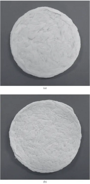
Figure 6. a) Porous SF membrane in the wet state; and b) after lyophilization, frozen in an ultrafreezer.
as discussed above. No other major physical or chemical changes were observed.
Although the lyophilized membranes presented similar physical, chemical and microstructural characteristics, their macroscopic as-pects were quite different. The quench freezing with liquid nitrogen, followed by lyophilization, promoted the collapse of the membranes, while the slow cooling performed by ultrafreezing preserved the membranes integrity, as presented in Figure 6, where the maintenance of shape and structure, when compared to the membrane in the wet state, is clearly shown.
During freezing, the physical environment of a protein may change dramatically leading to the development of stresses that
im-pact protein stability. Low temperature and ice formation are some of the stresses resulting during freezing23. The differences observed in the integrity of the porous SF membranes may be explained by the influence of the freezing rate. The surface area of ice generated after slow cooling is much smaller than when samples are rapidly cooled by immersion in liquid nitrogen. Quench freezing leads to the formation of a relatively large ice-water interface, while slow cooling leads to the formation of a smaller ice surface area. The denaturation during freezing is greater when proteins are frozen under conditions that generate a relatively large ice surface area. The observed results indicate that the freezing rate is an important factor that determines the integrity of lyophilized porous SF membranes11,23.
4. Conclusions
In this study, two freezing methods were performed for the lyophi-lization of porous silk fibroin membranes. Although the membranes presented similar physical, chemical and microstructural character-istics, the difference in freezing rate promoted the collapse of the membranes when quench frozen by liquid nitrogen, while the slow cooling performed by ultrafreezing preserved the membranes’ shape and integrity, making this method suitable for obtaining lyophilized porous silk fibroin membranes for use as biomaterials.
Acknowledgements
The authors thank FAPESP and CNPq for financial support.
References
1. Tamada Y. New process to form a silk fibroin porous 3-D structure. Biomacromolecules. 2005; 6(6):3100-3106.
2. Park K, Jung S, Lee S, Min B, Park W. Biomimetic nanofibrous scaffolds: preparation and characterization of chitin/silk fibroin blend nanofibers. International Journal of Biological Macromolecules. 2006; 38( 3-5):165-173.
3. Sashina E, Bochek A, Novoselov N, Kirichenko D. Structure and solubility of natural silk fibroin. Russian Journal of Applied Chemistry. 2006; 79(6):869-876.
4. Vasconcelos A, Freddi G, Cavaco-Paulo A. Biodegradable materials based on silk fibroin and keratin. Biomacromolecules. 2008; 9(4):1299-1305. 5. Roy I, Gupta M. Freeze-drying of proteins: some emerging concerns.
Biotechnology and Applied Biochemistry. 2004; 39(2):165-177. 6. Tang X, Pikal M. Design of freeze-drying processes for pharmaceuticals:
practical advice. Pharmaceutical Research. 2004; 21(2):191-200. 7. Sablani S. et al. Influence of shelf temperature on pore formation in garlic
during freeze-drying. Journal of Food Engineering. 2006; 80(1):68-79. 8. Luthra S, Obert J, Kalonia D, Pikal M. Impact of critical process
and formulation parameters affecting in-process stability of lactate dehydrogenase during the secondary drying stage of lyophilization: a mini freeze dryer study. Journal of Pharmaceutical Sciences. 2007; 96(9):2242-2250.
9. Wang W. Lyophilization and development of solid protein pharmaceuticals. International Journal of Pharmaceutics. 2000; 203(1-2):1-60. 10. Rambhatla S, Ramot R, Bhugra C, Pikal M. Heat and mass transfer
scale-up issues during freeze drying: II. control and characterization of the degree of supercooling. AAPS PharmSciTech. 2004; 5(4):e58. 11. Chang B, Kendrick B, Carpenter J. Surface-induced denaturation of
proteins during freezing and its inhibition by surfactants. Journal of Pharmaceutical Sciences. 1996; 85(12):1325-1330.
13. Kim H, Kim U, Leisk G, Bayan C, Georgakoudi I, Kaplan D. Bone regeneration on macroporous aqueous-derived silk 3-D scaffolds. Macromolecular Bioscience. 2007; 7(5):643-655.
14. Wang Y, Rudym D, Walsh A, Abrahamsen L, Kim HJ, Kim HS. et al. In vivo degradation of three-dimensional silk fibroin scaffolds. Biomaterials. 2008; 29(24-25):3415-3428.
15. Ki C, Park S, Kim H, Jung H, Woo K, Lee J. et al. Development of 3-D nanofibrous fibroin scaffold with high porosity by electrospinning: implications for bone regeneration. Biotechnology Letters. 2008; 30(3):405-410.
16. Lv Q, Feng Q. Preparation of 3-D regenerated fibroin scaffolds with freeze drying method and freeze drying/foaming technique. Journal of Materials Science: Materials in Medicine. 2006; 17(12):1349-1356. 17. Beppu M, Polakiewicz B, Nogueira G. PI: 0601975-72006. INPI/Brazil;
2006.
18. Li M, Lu S, Wu Z, Tan K, Minoura N, Kuga S. Structure and properties of silk fibroin-poly(vinyl alcohol) gel. International Journal of Biological Macromolecules. 2002; 30(2):89-94.
19. Lin F, Li Y, Jin J, Cai Y, Wei K, Yao J. Deposition behavior and properties of silk fibroin scaffolds soaked in simulated body fluid. Materials Chemistry and Physics. 2008; 111(1):92-97.
20. Um I, Kweon H, Park Y, Hudson S. Structural characteristics and properties of the regenerated silk fibroin prepared from formic acid. International Journal of Biological Macromolecules. 2001; 29(2):91-97.
21. Zoccola M, Aluigi A, Vineis C, Tonin C, Ferrero F, Piacentino MG. Study on cast membranes and electrospun nanofibers made from keratin/fibroin blends. Biomacromolecules. 2008; 9(10):2819-2825.
22. Kim HJ, Kim U, Kim HS, Li C, Wada M, Leisk G. et al. Bone tissue engineering with premineralized silk scaffolds. Bone. 2008; 42(6):1226-1234.