COMPARATIVE STUDY OF
DIFFERENTEDGE DETECTION
TECHNIQUES
Beant Kaur
A.P in ECE
RIMT-MAEC,MANDIGOBINDGARH(PUNJAB)
Mr.Anil Garg
A.P. in ECE
M.M.E.C,Mullana(HARYANA)
Abstract :
Detection of edge is a terminology in image processing and computer vision particularly in the areas of feature detection and extraction to refer to the algorithms which aims at identifying points in a digital image at which the image brightness changes sharply or more formally has discontinuities. The need of edge detection is to find the discontinuities in depth, discontinuities in surface orientation, changes in material properties and variations in scene illumination. Remote sensing images are generally corrupted from noise. Mathematical morphology is a new technique for edge detection .It is a theory and technique for analysis and processing of geometrical structures, based on set theory. In this paper square type structuring element of different size is implemented on different remote sensing images . The noise can also be suppressed by mathematical morphology. So by using mathematical morphology the image can be enhanced and the edges can be detected. In this paper ,the result of edge detection using mathematical morphology will be compared with sobel edge detector, Prewitt edge detector, laplician of gaussian edge detector and Canny edge detector.
Keywords: Mathematical morphology, edge detection, remote sensing images , canny edge detection ,erosion , dilation .
1 Introduction
2. Traditional methods of edge detection
2.1 Sobel operator
Sobel edge detection is used in image processing techniques .The sobel kernals are more suitable to detect edges along the horizontal(180 degree) and vertical axis(90 degree)[2]. The sobel operator is based on
convolving the image with a small, separable, and integer valued filter .
2.2 Canny Edge Detector
Canny edge detection is a multistage algorithm to detect a wide range of edges in images.It was presented in 1986 by Canny.The problem with this type of traditional edge detection approach is that a low threshold produces false edges ,but a high threshold misses important edges.
2.3 Prewitt edge detection
Prewitt operator edge detection masks are the one of the oldest and best understood methods of detecting edges in images. The strength of the edge at given location is then the square rote of the sum of the squares of two derivatives.
2.4 Robert edge detection
In Robert edge detection,the vertical and horizontal edges bring out individually and then put together for resulting edge detection.
Gx Gy
The two individual images Gx and Gy will be combined to get result.The Robert cross kernels are relatively small .Therefore they are highly susceptible to noise.
2.5 Laplician of Gaussian(LOG)
This method of edge detection was invented by Marr and Hildreth in 1980.In this method, the Gaussian filtering is combined with Laplician to break down the image where the intensity varies to detect the edges effectively. It finds the correct place of edges and testing wider area around the pixel .The disadvantage of LOG operator is that it can not find orientation of edge because of laplician filter[17].
3 Mathematical morphological operators
Mathematical Morphology is one of the most productive areas in image processing [18].The content of mathematical morphology is based on set theory.A structuring element is a special mask filter that enhances an input images .It can be of different sizes and of different shapes(square,diamond ,circle).Following are the main mathematical morphological operators:
1. Dilation 2. Erosion 3. Opening 4. Closing
3.1 Dilation
Dilation is defined as the maximum value in the window. Hence the image after dilation will be brighter or increased in intensity. It also expand the image and mainly used to fill the spaces. Dilation process expanding image objects by changing pixels with value of “0” to “1”.
3.2 Erosion
Erosion is just opposite to dilation. It is defined as the minimum value in the window .The image after dilation will be darker than the original image .It shrinks or thins the image.
+1 +2 +1 0 0 0 -1 -2 -1
-1 0 +1 -2 0 +2 -1 0 +1
0 +1 -1 0 +1 0
Erosion process shrinking objects or images by changing pixels with a value of “1” to “0”.
3.3 Opening and closing
Both parameters are formed by using dilation and erosion. In opening, firstly image will be eroded and then it will be followed by dilation.And in case of closing,firstly image will be dilated and then followed by erosion.
Root Mean Square Error
Mean square error of an estimator is to quantify the difference between an estimator and the true value of the quantity being estimated.
The mean square error is the squared error averaged over the M × N array.
M N
MSE=1/MN ∑∑ (f1(i,j)- f2(i,j))2 (1) i=1j=1
where f1 is output image and f2 is input image. Its value must be less.
RMSE=√MSE (2) Peak Signal to Noise Ratio
Peak signal to noise ratio is the ratio between the maximum possible power of a signal and the power of corrupting noise that affects the fidelity of its representation.It is the logarithmic function of the peak value of the image and the mean square error.
PSNR=10 LOG(2552/MSE) ……….(3)
4. Proposed Algorithm
START
Take remote sensing image.
Apply structuring element of
various sizes in different
directions with morphological
operators.
Find the edges by taking
difference between eroded and
dilated image in all directions.
Take the average of edges in all
direction
Is there any line
spacing gap in
resultant edge?
Dilate the image again.
Increase the intensity of
image if required.
Compare the results with
traditional techniques on the
basis of PSNR & RMSE
STOP
Yes
5 Implementation of method
1)First step is to take the remote sensing image .
2)Then apply the different structuring elements which are as follows: 1st method:
Se1= 1 1 1 Se2=1 0 1 0 0 0 1 0 1 1 1 1 1 0 1 (180 degree) (90 degree)
Se3=0 1 1 Se4=1 1 0 1 0 1 1 0 1 1 1 0 0 1 1 (135 degree) (45 degree)
2nd method:
Se1=1 1 1 1 1 Se2=1 1 0 1 1 1 1 1 1 1 1 1 0 1 1 0 0 0 0 0 1 1 0 1 1 1 1 1 1 1 1 1 0 1 1 1 1 1 1 1 1 1 0 1 1
(180 degree) (90 degree) Se3 = 0 1 1 1 1 Se4=1 1 1 1 0
1 0 1 1 1 1 1 1 0 1
1 1 0 1 1 1 1 0 1 1 1 1 1 0 1 1 0 1 1 1
1 1 1 1 0 0 1 1 1 1 (135 degree) (45 degree)
3rd method:
Se1=0 0 0 0 0 Se2=0 0 1 0 0
0 0 0 0 0 0 0 1 0 0 1 1 1 1 1 0 0 1 0 0
0 0 0 0 0 0 0 1 0 1 0 0 0 0 0 0 0 1 0 1
(180 degree) (90 degree)
Se3= 1 0 0 0 0 Se4=0 0 0 0 1 0 1 0 0 0 0 0 0 1 0 0 0 1 0 0 0 0 1 0 0 0 0 01 0 0 1 0 0 0 0 0 0 0 1 1 0 0 0 0 (135 degree) (45 degree)
4th method:
Se1=0 0 0 0 0 Se2=0 0 1 0 0
0 0 0 0 0 0 0 1 0 0 1 1 1 1 1 0 0 1 0 0
0 0 0 0 0 0 0 1 0 1 0 0 0 0 0 0 0 1 0 1 (180 degree) (90 degree)
Se5= 0 1 0 0 0 Se6== 0 0 0 0 0 0 0 0 0 0 0 0 0 0 1 0 0 1 0 0 0 0 1 0 0 0 0 0 0 0 1 0 0 0 0
0 0 0 0 1 0 0 0 0 0 (112.5 degree) (22.5 degree)
Se7= 0 0 0 1 0 Se8=0 0 0 0 0 0 0 0 0 0 1 0 0 0 0 0 0 1 0 0 0 0 1 0 0 0 0 0 0 0 0 0 0 0 1 0 1 0 0 0 0 0 0 0 0 (202.5 degree) (157.5 degree)
5th method:
Se1=1 1 1 1 1 Se2=1 1 0 1 1 1 1 1 1 1 1 1 0 1 1 0 0 0 0 0 1 1 0 1 1 1 1 1 1 1 1 1 0 1 1 1 1 1 1 1 1 1 0 1 1 (180 degree) (90 degree) Se3 = 0 1 1 1 1 Se4=1 1 1 1 0 1 0 1 1 1 1 1 1 0 1
1 1 0 1 1 1 1 0 1 1 1 1 1 0 1 1 0 1 1 1
1 1 1 1 0 0 1 1 1 1 (135 degree) (45 degree)
Se5= 1 0 1 1 1 Se6= 1 1 1 1 1 1 1 1 1 1 1 1 1 1 0 1 1 0 1 1 1 1 0 1 1 1 1 1 1 1 0 1 1 1 1 1 1 1 0 1 1 1 1 1 1 (112.5 degree) (22.5 degree) Se7=1 1 1 0 1 Se8=1 1 1 1 1 1 1 1 1 1 0 1 1 1 1 1 1 0 1 1 1 1 0 1 1 1 1 1 1 1 1 1 1 1 0 1 0 1 1 1 1 1 1 1 1
(202.5 degree) (157.5 degree)
3)And after the implementation of above all the structuring elements with dilation and erosion operators. 4) Find the edges by taking difference between dilated and eroded image(in all directions).then take the average of all the resultant images i.e suppose in case of 2nd method Se1 + Se2 +Se3 +Se4 / 4,
similarly find the edges for all the methods.
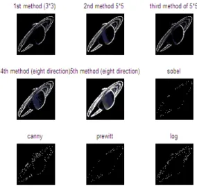
6 Results
Fig. 1 Result of different edge detection methods of moon image
7 Comparison
Fig. 3 shows result of different edge detection methods of multispectral image
Table 1 RMSE and PSNR value of moon image Table 2 RMSE & PSNR value of Saturn image
Table 3 shows RMSE & PSNR values of multispectral image
S.N O.
Method of implementation
RMSE PSNR
1 1st method 65.2755 34.5546
2 2nd method 65.5411 34.5370
3 3rd method 63.0814 34.7031
4 4th method 68.9913 34.3142 5 5th method 75.1472 33.9430
6 6th method 65.7139 34.5256
7 7th method 65.7007 34.5264
8 8th method 65.7155 34.5255
9 9th method 65.6997 34.5265 S.N
O.
Method of implementation
RMSE PSNR
1 1st method 78.6827 32.9389
2 2nd method 73.3573 33.2433
3 3rd method 80.3755 32.8465
4 4th method 70.2265 33.4327 5 5th method 68.5267 33.5391
6 6th
method(sobel)
99.2341 31.9311
7 7th
method(canny)
99.1865 31.9332
8 8th
method(prewitt)
99.2343 31.9311
9 9th method(log) 99.1948 31.9328
S.N O.
Method of implementation
RMSE PSNR
1 1st method 136.8343 32.8235
2 2nd method 134.0823 32.9117
3 3rd method 142.6747 32.6419
4 4th method 129.2837 33.0700
5 5th method 124.5454 33.2321
6 6th method(sobel) 170.7682 31.8613
7 7th method(canny) 170.7135 31.8627
8 8th
method(prewitt)
170.7697 31.8613
8 Conclusion
From the results, it is concluded that the edge detection using mathematical morphology is more efficient than the traditional methods. From the results and comparison of the different methods of edge detection,it is concluded that the mathematical morphological edge detection is better than the traditional method.In this work ,edges of images using mathematical morphology and traditional methods like sobel, canny,Prewitt and Laplician of Gaussian method has been studied and compared on subjective basis as well as objective manner. In this paper,edge detection is performed using mathematical morphology of remote sensing images. and different methods using different structuring element in multidirections has been studied and compared.The comparison shows that the root mean square error(RMSE) values of mathematical morphology is less and high in traditional methods.and also the Peak Signal to Noise Ration is high in case of mathematical morphology edge detection techniques as compared to traditional methods. The main advantages of mathematical morphology are direct geometric interpretation, simplicity and efficiency in hardware implementation.
References
[1] Mr.Salem Saleh Al-amri,Dr.Khamitkar S.D,” A comparative study of Removal Noise from Remote sensing Image”,IJCSI International Journal of Computer Science Issues,Vol.7,Issue .1,January 2010 32 issn (online):1694-0784 ISSN(Print):1694-0814
[2] S.Lakshmi,Dr. V .Sankaranarayanan,” A study of Edge Detection Techniques for Segmention Computing Approaches”, IJCA special issue on “ Computer Aided Soft Computing Techniques for imaging and Biomedical Applications”CASCT,20
[3] M Rama Bai,”A new approach for border extraction using morphological methods”,International Journal of Engineering Science and Technology Vol.2(8),2010,3832-3837
[4] Erick Lopez Ornelas,”High Resolution Images:Segmenting Extracting Information and GIS Integration”,World Academy of science ,Engineering and Technology 54 ,2009
[5] V.Shrimalli, R.S.Anand ,R.K.Srivastav,”Medical feature based evaluation of structuring elements for morphological enhancement of ultrasonic images”, Journal of Medical Engineering & Technology , Vol. 33,No. 2,February 2009,158-169
[6] Rahul Gaurav,”A Mathematical Morphological Perspective in World of images ”,Seminar on spatial Information Retrieval Analysis ,Reasoning and Modelling 18th
– 20th
March 2009,ISI- DRTC ,Bangalore ,India
[7] Rui Guo,Daoliang Li,”Road Detection Method for Land Consolidation Using Mathematical Morphology from High Resolution Image”, Proceedings of the 13th
WSEAS International Conference on Applied Mathematics(MATH’08)
[8] Yu Lei and Nie jiafa,”Subpixel EdgevDetection Based on Morphological Theory”,Proceedings of the world Congress on Engineering and Computer Science 2008 WCECS 2008 ,October 22-24, 2008 ,San Francisco,USA
[9] M.Kowalczyk,P.Koza,P.Kupidura,J.Marciniak,”Application of Mathematical Morphology Operations for Simplication and Improvement of Correlation of Images in Close –Range Photogrammetry”, The International Archieves of the Photogrammetry ,Remote Sensing and Spatial Information Sciences Vol.XXXVII Part B5.Beijing 2008
[10] Jie Yanga ,Ran Yanga ,Shigao Lib,S.Shoujing Yina,Qianqing Qina,” A Novel Edge Detection Based Segmentation Algorithm for Polarimetric Sar Images”, The International Archives of the Photogrammetry, Remote sensing and Spatial Information ,Sciences .Vol.XXXVII,Part B7.Beijing 2008
[11] T.A. Mohmoud ; S.Marshal,” Edge –Detected Guided Morphological Filter For Image sharpening “,Hindawi Publishing orporation EURASIP Journal on image and video Processing volume 2008
[12] Tarek A. Mahmoud,Stephen Marshall,” Medical Image Enhancement using Threshold Decomposition Driven Adaptive Morphological Filter”, 16th
European Signal Processing Conference (EUSIPCO 2008),Lausanne,Switzerland ,August 25-29,2008
[13] Yee Yee Htun,Dr. Khaing Khaing Ayez,” Fuzzy Mathematical Morphology Approach in Image Processing”, World Academy of Sciences ,Engineering and Technology 42,2008
[14] Atif Bin Mansoor ,Ajmal s Milan ,Adil Khan ,”Fuzzy Morphology for Edge detection and Segmentation”, G.Bebis et al.(Eds.): ISVC 2007 , Part II,LNCS 4842,pp.811-821,2007
[15] Bouchet A,Pastore J,Ballarin V,” Segmentation of medical Images using Fuzzy Mathematical morphology”, JCST [16] Zaharescul,”Morphological Enhancement of Medical Images in a logarithmic Image Environment”,15th
European Signal Processing Conference (EUSIPCO 2007),published in IEEE 2007
[17] Mohamed Roushdy,”Comparative Study of Edge detection Algorithms Applying on Grayscale Noisy image using Morphological Filter”, GVIP Journal , Volume 6,Issue 4,December ,2006
[18] Alper Pahsa,”Morphological Image Processing With Fuzzy Logic”, Havacilik Vc Uzay Teknolojileri Der Gisi Ocak 2006,CICK 2SAY13(27-34)
[19] Elbehiery ,A.Hefnawy and M.Elewa,” Surface Defects Detection for ceramic Tiles Using image processing and Morphology 5 2005