Flexible Electrochromic Windows: A Comparison Using Liquid and
Solid Electrolytes
Emerson Marcelo Girotto, and Marco-A. De Paoli*
Laboratório de Polímeros Condutores e Reciclagem, Instituto de Química,
Unicamp,C.P. 6154, 13083-970 Campinas - SP, Brazil
Neste trabalho foram montados e caracterizados dois dispositivos eletrocrômicos (ou janelas eletrocrômicas) utilizando como materiais opticamente ativos polímeros instrinsecamente con-dutores. Os materiais usados na montagem foram os mesmos, exceto pelo eletrólito usado. No primeiro foi usado como eletrólito uma solução de carbonato de propileno e no segundo o elastômero poli(epicloridrina-co-oxido de etileno), ambos contendo LiClO4. A condutividade elétrica do
eletrólito líquido é aproximadamente duas ordens de grandeza maior (10-3 S cm-1) do que a do eletrólito sólido e foram obtidos excelentes resultados do ponto de vista eletrocrômico em ambos os casos. A eficiência eletrocrômica em 640 nm foi calculada em 700 C cm-2 para o dispositivo com eletrólito liquido e 360 C cm-2 para o dispositivo montado com eletrólito sólido. O uso de dispositivos eletrocrômicos de estado sólido tem chamado bastante atenção e suas vantagens são discutidas.
In the present work, two electrochromic devices (or electrochromic windows) based on intrin-sically conducting polymers were assembled and characterized. For both devices, the materials used on the assembling were the same except for the electrolyte layer. In the first, we used as electrolyte a propylene carbonate solution and in the second the elastomer poly(epichlorohydrin-co-ethylene oxide), both containing LiClO4. The conductivity of the liquid electrolyte (10-3 S cm-1) is
approxi-mately two orders of magnitude higher than for the solid electrolyte and we obtained very good electrochromic properties in both cases. The calculated electrochromic efficiency at 640 nm was 700 C cm-2 for the liquid electrolyte device and 360 C cm-2 for the solid state device. Solid state electrochromic windows have been investigated and some of its advantages over windows with liquid electrolytes are discussed.
Keywords: electrochromic window, polymeric electrolyte, conducting polymer
Introduction
Recent publications of books1 and reviews2 on electro-chromism and electrochromic devices demonstrate the in-terest in this area of research. In a recent paper3 we used a dianionic dye to enhance the optical contrast of polypyr-role. Not only the use of dyes4, but other aspects are important: sol-gel deposition film methods5, temperature of deposition6, counterion color influence7, oxygen flow dur-ing sputtered films8, coating the electrochrome with thin gold or platinum layer9, etc.
Nowadays the progress in science and technology points to new systems for energy storage or optics based on all polymeric (due to its lower costs) and flexible (due to its easy handling) devices, the so-called “cheap and bendy” devices10. Undoubtedly, the electrolyte plays an important role in the development of this technology. Polymeric solid
electrolytes can be used without loss of the electrochromic parameters since the interaction polymer-electrolyte-counter electrode is satisfactory. These desirable conditions could be reached studying new electrode-electrolyte prepa-ration methods and perhaps a simultaneous film-electrolyte preparation.
The main functional features of commercial electro-chromic devices for architecture and automotive applica-tions are the reduction of light and heat transfer for thermal well-being and daylight control or glitter reduction for thermal and visual comfort. According to Monk and cols.1, electrochromic systems are divided as follow: (i) those constructed with electrochromes always in solution, (ii) with colorless electrochromes initially in solution and be-coming a colored solid after electron transfer and (iii) with electrochromes as solid films on transparent electrodes. Indeed, the third type presents several advantages over the Article
e-mail: [email protected]
others when using solid electrolyte, mostly related to pre-vention of leaking, sealing and solvent evaporation. Several works have focused on the use of polymeric electrolytes in electrochromic devices11-18,27 and, more recently, these have also been used for all plastic and flexible devices17. Notwithstanding these disadvantages, electrochromic de-vices assembled in liquid configurations (liquid, gel or highly plasticized polymer electrolyte) have demonstrated good optical contrast, stability and response time18. Often dimethylformamide or propylene carbonate (PC) solutions containing LiClO4 are used as electrolytes. For layered systems there are interfaces that significantly influence the kinetics assigned to mass and charge transport. A system that could facilitate these transports will present satisfac-tory results using the appropriate layer components. The rate limiting process usually encountered in type (iii) sys-tems is ionic charge transport through the solid electro-chrome as well as the diffusing species that enters the electrochrome via the electrolyte film interface.
In this work we describe the results of two electro-chromic devices assembled in the same configuration ex-cept for the electrolyte used: propylene carbonate (liquid) or the elastomer poly(epichlorohydrin-co-ethylene oxide), P(EPI-EO) (solid), both containing LiClO4. The cathodic electrochrome used was poly(3,4-ethylene dioxythio-phene)-poly(styrene sulphonate) (PEDT-PSS, Bayer) and the anodic was polypyrrole-dodecylsulfate-indigo carmine (PPy-DS-IC)3. PEDT is used as anti-static coating for plas-tics, especially photographic films. Recently, its applica-tions have been extended to solid electrolyte development for capacitors, through-hole plating of printed circuit boards19, biosensors20 and photoelectrochemical cells21,22.
Experimental
The electrochromes were initially studied in situ as single electrodes in an electrolytic cell having platinum as counter electrode, AgAgCl reference electrode and a pro-pylene carbonate solution of LiClO4 (1.0 mol L-1) as elec-trolyte. This was done to balance the charge regarding the opposite electrochromes. The redox charge was measured by chronoamperommetry and controlled by the synthesis charge. In a recent work3 we have described in details the method of synthesis and electrochromic characterization of PPy-DS-IC. As transparent electrodes, we used ITO-PET (poly(ethylene terphthalate) coated with indium doped tin oxide (I.S.T. Co., Belgium, 60 Ω cm-2, 175 µm thickness). The cathodic electrochrome was characterized in the same way but it was prepared by casting its diluted commercial solution (Baytron-P®, Bayer) on ITO-PET electrodes. The solid electrolyte was prepared by dissolving 0.60 g P(EPI-EO) (Daiso Co. Ltd.) and 0.032 g of LiClO4 (Aldrich) in 10 mL of tetrahydrofuran (Merck). These quantities give n = 29, where n is the ratio between the number of moles
of oxygen atoms in the copolymer chain and the number of moles of metallic cation, n = [O]/[Li]. This solution was deposited on the modified electrodes and the solvent was evaporated until a plastic-like film was formed. The elec-trodes were carefully pressed until the polymeric electro-lyte fixed them. Traces of THF were not completely removed. The solid electrolyte thickness was controlled with an adhesive tape spacer (35 µm thickness) and the active area was 1.0 cm2 for both devices. The liquid elec-trolyte was a 1.0 mol L-1 solution of LiClO
4 (Aldrich) in propylene carbonate (Riedel-de-Haën). This solution was deposited on the electrodes and the cells were assembled as described above maintaining the same distance between electrodes. The devices were assembled under atmospheric conditions. The measurements were carried out by placing the devices in the sample compartment of a spectro-photometer (Hewlett-Packard, 8452A) and switching the applied potential using a PG-05 Omnimetra poten-tiostat/galvanostat interfaced to a computer. For electro-chromic device investigations, a simple two-electrode system was constructed in a sandwich configuration. Im-pedance measurements were performed using an Echo-Chemie Autolab PGSTAT10 potentiostat with a frequency response analyzer module. Sinusoidal perturbations of ±0.010 V were applied between 0.1 Hz and 10 kHz with polarized conditions (-1.5 to +1.5 V with intervals of 0.5 V). The ambient temperature and relative humidity were controlled and maintained at 20 ± 1 °C and ca. 45%, respectively.
Results and Discussion
refer-ence electrode. Thus, one of the electrochrome modified electrodes is used as reference. Hence, the potentials de-scribed in this work are relative to a PEDT-PSS electrode that was circuited as the counter-electrode.
After assembling, the devices were submitted to large potential range cyclic voltammetry (-2.5 to 4.0 V) simulta-neous to measurement of the transmittance at 640 nm, in order to verify the minimum cathodic and anodic potentials required to guarantee a reasonable chromatic contrast value (Fig. 1). Clearly, the potentials of -1.5 and 1.5 V are optimal values to assure a ∆%T640nm of 41% (liquid electrolyte) and 31% (dry polymeric electrolyte).
The stability was tested by performing 500 square wave double potential steps at -1.5 and 1.5 V with 15 s each of polarization (Fig. 2). This chronoamperometric experiment permits us to evaluate the cycle life, calculate the coloration efficiency, response time, and write-erase efficiency, Ta-ble 1.
We noted a progressive fall in the electrochromic prop-erties as a function of the number of potential steps. The previous characterizations of PEDT-PSS and PPy-DS-IC as single electrodes have showed good electrochromic properties and stability. However, the films of PPy-DS-IC used in the device were deposited with smaller thickness to achieve a charge capacity equal to PEDT-PSS. This may increase the mechanical stress caused by the redox process
Figure 1. Transmittance variation at 640 nm measured during a cyclic voltammetry (-2.5 to 4.0 V vs. PPI-DS-IC) for liquid and polymeric electrolyte devices.
Figure 2. a) Double potential step and b) Optical contrast (640 nm) during 15 s of polarization at -1.5 and +1.5 V using liquid electrolyte (dotted line) or polymeric electrolyte (full line) devices.
Table 1. Calculated electrochromic parameters for liquid (liq) and polymeric (pol) electrolyte devices.
ηb [a] [cm2C-1] ηc [b] [cm2C-1] τb [c] [s] τc [d] [s] ∆%T640nm [e] [%]
liq pol Liq pol liq pol liq pol liq pol
714 404 747 319 7 9 4 4 47 52
of insertion/expulsion of ions. Besides, for electrochromic applications the humidity conditions are not so critical as when working with lithium based battery systems, so we did not work under strictly anhydrous conditions. The water present in the electrolytes could have reacted under polari-zation producing O2 and H2, leading to degradation of PPy-DS-IC (reaction with O2), and the formation of bub-bles, decreasing the electrolyte-film contact. The relation between absorption change and the injected charge per unit area gives η. The value obtained in this work is notably higher than some values found in the literature for inorganic or organic electrochromes and devices1,14. This is caused by the high optical contrast of the device (Fig. 2b) and the low charge required to promote the optical change. In general, organic electrochromes exhibit a greater η value than inorganic species because the molar absorptivities of the former are usually higher2. Figure 2b apparently shows a disagreement with Fig. 1, where we can see the higher ∆%T for the last. The difference is that in the experiment of Fig. 1, the chromatic contrast at 640 nm was registered during cyclic voltammetry and in the experiment of Fig. 2b the spectra were registered during a constant polarization of ca.1 min (-1.5 and/or 1.5 V). This corresponds to the measurement of the response time of the devices.
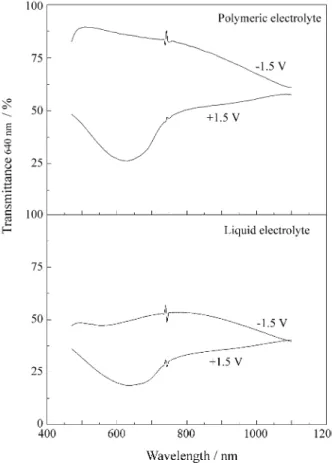
Figure 3 shows the spectra of the bleached and colored form of the two devices. The write-erase efficiency for the device assembled with the polymer electrolyte is remark-able in comparison to the liquid.
As described above, the only difference between the devices is the electrolyte layer; one is an elastomeric poly-mer and the other a liquid solution, but both have the same thickness and contain LiClO4. Hence, we could assign the different behavior to the electrolyte layer. Resuming, it is clear that the device assembled with the polymeric electro-lyte shows a shorter response time and, moreover, it is more sensitive at the potential of -1.5 V, i.e., in the bleached form. During the coloring and bleaching steps the current decays to zero for the device with the liquid electrolyte but not for the device with the polymeric electrolyte (Fig. 2a). Further, during the coloring step of the device with the polymeric electrolyte, the current decays to zero at the same rate for the bleaching step, but the transmittance reaches a constant value faster than during the bleaching process. This indi-cates that the kinetics of PPy-DS-IC oxidation/PEDT-PSS reduction is faster than that of the reverse process, path two in Fig. 4.
The color persistence in the electrochromic devices is an important feature since it is directly related to aspects involved in its utilization and energy consumption during use. For electrochromic applications, electrochromic de-vices with good optical memories are necessary, avoiding a re-polarization of the electrochromes for the desirable color constancy. The color stability for the bleached and
colored states of the electrochromic devices were investi-gated just after polarizations (-1.5 and 1.5 V) at open circuit during 3.5 h (Fig. 5). For the device with polymeric elec-trolyte polarized in the bleached state, %T640 = 80%. After 1 h under an open circuit the %T640 changes to 65% and remains constant. When polarized in the colored state the device presents %T640nm = 28%, while after 1 h under an open circuit the %T640 changes to 40% and remains con-stant. These results indicate that this system does not reach equilibrium under open circuit conditions and presents a reasonable optical memory.
Electrochemical impedance spectroscopy measure-ments were carried out to determine the resistance of the electrolyte and to investigate its effect on the electro-chromic properties of the devices, mainly on the response time. Nyquist plots for the devices (Fig. 6) were analyzed on the basis of a modified Randles circuit and using a fitting software29. In Fig. 6 the points marked (x) represent the semi-circle fitting done by the software using an equivalent circuit. The resistance imposed by the electrolyte could be estimated by the first intersection of the curve with the real (Z) axis, Re. However, it does not give the real value of the electrolyte resistance, because the electrochromic electrodes are not blocking, thus, Re is the sum of the resistance of the electrolyte + PET-ITO + electrochromes.
Table 2 shows the Re values for the devices. Taking into account that the single difference between the two devices is the electrolyte layer, we observe that the values are very close and we may affirm that the conductivity of P(EPI-EO)/LiClO4 (σ = 10-5 S cm-1 at 30 °C)30 is of the same order of magnitude as the liquid electrolyte, PC-LiClO4.
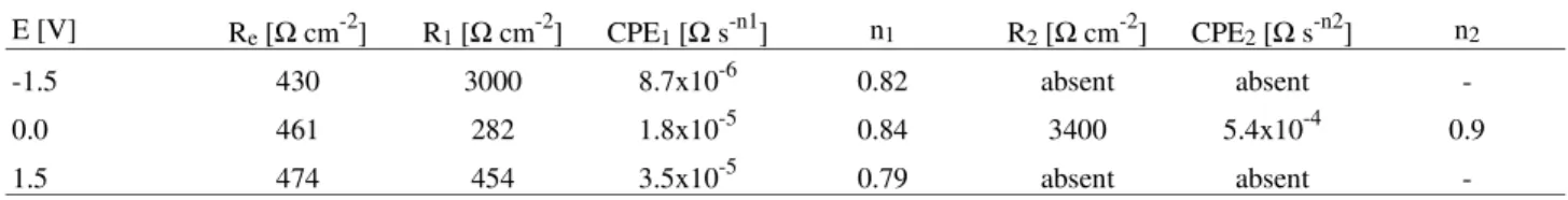
The calculated double layer capacitance values (CPE) are closer to the typical values obtained for interfaces than for those found for bulk characteristics31. In particular, we have four interfaces to be considered: (i) PET-ITO PPy-DS-IC, (ii) PPy-DS-IC electrolyte, (iii) electro-lyte PEDT-PSS and (iv) PEDT-PSS ITO-PET. Bulk phenomena and the polymer electrode interface should be detected at higher frequencies, thus the semicircles found in our experiments are probably due to a polymer electro-lyte interface phenomena. Table 3 summarizes the results of the fitted parameters calculated from the impedance measurements.
At negative potentials we have the following situation: reduced PPy-DS-IC (insulating character) and oxidized PEDT-PSS (conducting character). Hence, the increase of Re in the direction -1.5 → 1.5 V indicates that PEDT-PSS reduction predominates over the system, becoming itself more resistive. At 0.0 V we observe two semicircles due to the PPy-DS-IC electrolyte and electrolyte PEDT-PSS interfaces, because of their partially conducting states. In the direction 1.5 → -1.5 V we have reduced PPy-DS-IC and oxidized PEDT-PSS and the first semicircle disap-pears, indicating that the PEDT-PSS modified electrode has N
H
(DS-nIC-2m)-(2m+n)(Li+)(2m+n)(ClO4-)(2m+n) +(2m+n)
S
O O
(PSS-)(2m+n)(Li+)(2m+n) +
N H
(DS-nIC-2m)-(2m+n)(Li+)(2m+n) + S
O O
(PSS-)(2m+n)(Li+)(2m+n)(ClO4-)(2m+n) +(2m+n)
dark blue
transparent pale yellow
DS- = CH3(CH2)11OSO3 -N
N O
O H
H
S O
O
O O
O O S
H
H H
H
H
H
IC-2 = PSS =
SO3
-n
Figure 4. Electrochemical processes and color change for the devices.
the polymer in its full semiconductor state, showing a semi-metallic like behavior. The absence of semicircles in the liquid electrolyte device at -1.5 and 0.0 V indicates that, in this case, some of the considerable interfaces described above are less defined because the polymers are swollen by the electrolyte.
Conclusions
The electrochromic parameter, η, presented by the elec-trochromic devices described in this work is clearly higher than those values found in the literature, even for inorganic electrochromes1. For the liquid electrolyte device we found an exceptional value of more than 700 C-1 cm2 while an average value of ca. 360 C-1 cm2 was obtained for the polymer electrolyte device. In general, these values are assigned to optimal coloration efficiency with a minimum injected charge. The higher η for the liquid electrolyte device, as well as its shorter response time, is probably due to the polymer-electrolyte contact. A liquid electrolyte could more efficiently swell the electrochrome, increasing the amount of injected electrons provided by a better ion exchange in the polymer electrolyte interface.
Figure 6. Nyquist plots for assembled devices using polymeric and liquid electrolytes at steady state potentials of -1.5 ( ), 0.0 (∆) and 1.5 V (O). The curves were vertically shifted for easier comparison. Points marked (x) represent the data simulated with the software used.
Table 2. Electrolyte resistance values (Re /Ω cm-2) in the assembled devices with PC-LiClO4 and P(EPI-EO)-LiClO4, determined from
elec-trochemical impedance spectroscopy experiments.
Potential / V Re (PC) Re (P(EPI-EO))
-1.5 550 474
0.0 548 460
1.5 583 430
Table 3. Parameters obtained by fitting the electrochemical impedance spectroscopy data for the device with polymeric electrolyte at different polarization potentials.
E [V] Re [Ω cm-2] R1 [Ω cm-2] CPE1 [Ω s-n1] n1 R2 [Ω cm-2] CPE2 [Ω s-n2] n2
-1.5 430 3000 8.7x10⁻⁶ 0.82 absent absent
-0.0 461 282 1.8x10⁻⁵ 0.84 3400 5.4x10⁻⁴ 0.9
-Although our devices did not present good environ-mental and redox stability due to the PPy-DS-IC layer, we demonstrated that these devices could be suitable for tech-nological applications after their method of assembling and/or preparation is improved. Assembling an all-poly-meric flexible electrochromic device in the form of a film opens the perspective of applying these films on already existent glass windows. This will save the costs of substi-tuting windows and frames in existing buildings.
Acknowledgments
The authors thank FAPESP (proc. 97/02156-3) for a Ph.D. Fellowship and financial support (96/9983-0), Daiso Co. Ltd. and Bayer S.A. for P(EPI-EO) and Baytron-P (Baytron-PEDT-Baytron-PSS) samples. We also thank Dr. W. A. Gazotti for useful comments.
References
1. Monk, P.M.S.; Mortimer, R.J.; Rosseinsky, D.R. Electrochromism: Fundamentals and Applications, VCH, New York, Ch. 2, 1995.
2. Mortimer, R.J. Chem. Soc. Rev. 1997, 26, 147. 3. Girotto, E.M.; De Paoli, M.-A. Adv. Mater.1998, 10,
790.
4. Yano, J. J. Electrochem. Soc.1997, 144, 477. 5. Aegerter, M.A.; Avellaneda, C.O.; Pawlicka, A.; Atik,
M. J. Sol-Gel Sci. Technol.1997, 8, 689.
6. Kubo, T.; Nishikitani, Y. J. Electrochem. Soc.1998, 145, 1729.
7. Kulesza, P.J.; Malik, M.A.; Mieccznikowski, K.; Wolkiewics, A. J. Electrochem. Soc.1996, 143, L10. 8. Scarminio, J.; Lourenço, A.; Gorenstein, A. Thin Solid
Films1997, 302, 66.
9. Yao, J.N.; Yang, Y.A.; Loo, B.H. J. Phys. Chem. B
1998, 102, 1856.
10. Ziemells, K. Nature1998, 393, 619.
11. Duek, E.A.R.; De Paoli, M.-A. Mastragostino, M.; Adv. Mater.1993, 5, 650.
12. Carpenter, M.K.; Conell, R.S. J. Electrochem. Soc.
1990, 137, 2464.
13. Arbizzani, C.; Mastragostino, M.; Meneghello, L.; Morselli, M.; Zanelli, A. J. Appl. Electrochem. 1996, 26, 121.
14. a) Mastragostino, M.; b) Scrosati, B.; c) Abraham, K.M. In Applications of Electroactive Polymers, Scrosati, B., Ed.; Chapman&Hall, London, Ch. 7, 8, 3, 1993.
15. Kim, E.; Lee, K.-Y.; Lee, M.-H.; Shin, J.-S.; Rhee, S.B. Synth. Met.1997, 85, 1367.
16. Michalak, F.; Aldebert. P. Solid State Ionics1996, 85, 265.
17. De Paoli, M.-A.; Casalbore-Miceli, G.; Girotto, E.M.; Gazotti, W.A. Electrochim. Acta 1999, 44, 2983. 18. Rocco, A.M.; De Paoli, M.-A.; Zanelli, A.;
Mas-tragostino, M. Electrochim. Acta1996, 41, 2805. 19. Jonas, F.; Morrison, J.T. Synth. Met.1997, 85, 1397. 20. Yamato, H.; Ohwa, M.; Wernet, W. J. Electroanal.
Chem. 1995, 397, 163.
21. Yohanes, T.; Inganäs, O. Solar En. Mater. Solar Cells
1998, 51, 193.
22. Radhakrishnan, S.; Somani, P. Mat. Lett. 1998, 37, 192.
23. Bange, K.; Gambke, T. Adv. Mater. 1990, 2, 10. 24. Nijnatten, P.A.; Spee, C.I.M.A. J. Non Crystal. Sol.
1997, 218, 302.
25. Becker, H.; Witthopf, H. Proceedings of the 3rd Inter-national Meeting on Electrochromism London, 1998, Abstract 8D.
26. Tassi, E.L.; De Paoli, M.-A. Electrochim. Acta1994, 39, 2481.
27. Gazotti, W.A.; De Paoli, M.-A.; Casalbore-Miceli, G.; Geri, A. Adv. Mater. 1998, 10, 60.
28. De Paoli, M.-A.; Duek, E.A.R. Adv. Mater. 1992, 4, 287.
29. Boukamp, B.A.; EQUIVCRT, Version 4.51, Univer-sity of Twente, The Netherlands 1995.
30. Goulart Silva, G.; Lemes, N.H.T.; Polo da Fonseca, C.N.; De Paoli, M.-A. Solid State Ionics1997, 93, 105. 31. Johnson, B.W.; Read, D.C.; Christensen, P.; Hamnett, A.; Armstrong, R.D. J. Electroanal. Chem.1994,364, 103.
Received: February 18, 1999