0103 - 5053 $6.00+0.00
A
rti
c
le
*e-mail: [email protected]
EIS and Microstructural Characterization of Artificial Nitrate Patina Layers Produced
at Room Temperature on Copper and Bronze
R. del P. Bendezú H., R. P. Gonçalves, A. C. Neiva and H. G. de Melo*
Departamento de Engenharia Química, Escola Politécnica, Universidade de São Paulo, Av. Prof. Luciano Gualberto, Travessa 3, 380, Cidade Universitária “Armando de Salles Oliveira”
05508-900 São Paulo-SP, Brazil
Camadas artificiais de pátina são freqüentemente usadas para dar aparência final e para restaurar superfícies danificadas de cobre e bronze antigos. O principal inconveniente deste processo é que freqüentemente se requer o aquecimento da superfície ou então a imersão total do objeto metálico na solução de pátina, o que às vezes é impossível de realizar, principalmente em se tratando de monumentos grandes e/ou expostos ao ar livre, e também de objetos antigos. No presente trabalho, o comportamento de corrosão do cobre e do bronze em solução de NaCl foi comparado com a resposta destes mesmos metais quando recobertos com dois tipos diferentes de pátinas artificiais a base de nitratos, as quais foram obtidas à temperatura ambiente mediante a aplicação das soluções sobre as superfícies com auxílio de um bastão de algodão. As técnicas eletroquímicas utilizadas foram a Espectroscopia de Impedância Eletroquímica (EIE) e curvas de polarização anódica. As curvas anódicas mostraram que, para tempos curtos de imersão, a presença da camada de pátina não muda o mecanismo de corrosão das amostras, o qual parece ser dominado pela difusão de um complexo de Cu solúvel para o seio da solução, como proposto na literatura. Entretanto, os diagramas de EIE evidenciaram diferenças entre as respostas das amostras tratadas com pátina ou não. Enquanto nestas últimas os diagramas exibiram um fenômeno controlado por difusão na região de baixas freqüências, nas primeiras a resposta foi dependente da estrutura das camadas de pátina. Além disso, as respostas de impedância indicaram diferenças entre o comportamento de corrosão das amostras tratadas com as diferentes soluções de pátina, aspecto que não foi evidenciada pelas curvas de polarização anódica mas que está de acordo com imagens obtidas por MEV.
Artificial patina layers are often used to give final appearance and also to restore damaged old copper and bronze surfaces. The main inconvenient of this process is that it frequently requires surface heating or total immersion of the metallic object in the patina solution, which is sometimes impossible to accomplish, mainly with big outdoor exposed objects or ancient artefacts. In the present investigation the corrosion behaviour in NaCl solution of bare copper and bronze was compared with the response exhibited by samples of these metals covered with two different artificial nitrate-based patinas obtained at room temperature by dabbing a soaked cotton swab above their surfaces. The electrochemical techniques used to assess the response of the samples were electrochemical impedance spectroscopy (EIS) and anodic polarization curves. The anodic polarization responses have shown that, for short immersion times, the presence of the patina layer does not change the corrosion mechanism of the samples, which seems, as proposed in the literature, to be dominated by the diffusion of a soluble Cu complex to the bulk of the solution. However, EIS diagrams have evidenced differences between the responses of the bare and patina-treated samples. While in the formers the diagrams exhibited a low frequency diffusion controlled phenomenon, in the latter the response is dependent of the structure of the patina layers. Moreover, EIS response have indicated differences between the corrosion behaviour of the samples treated with the different patina solutions, which were not evidenced by the anodic polarization curves, but which are in accordance with the microstructural features revealed by SEM images.
Introduction
Special colour effects on the surface of metallic art objects and architectonic components are often created by artists and architects through the use of artificial stable
corrosion layers, usually denominated artificial patinas.1
This kind of treatment is also employed by restaurateurs to mimic old artificial or natural layers on replacement pieces or cleaned surfaces in the restoration and conservation of the architectural, historical and ethnological metallic heritage. In the last few years, the interest of corrosion researchers has turned to artificial patinas not only because of these direct applications in the cultural heritage conservation, but also because they can be an important tool for understanding the long-term corrosion behaviour of ancient metallic pieces that have been previously exposed to soil, water or open air atmosphere.
In the science of conservation, studying patinas formed in natural environments is difficult because they can take
years to form.2 Moreover, each ancient piece can be
considered as unique, as it has not been submitted to commercial manufacturing methods and has been exposed to particular environmental conditions, making it difficult to
develop general models,3 or either to check for reproducibility.
Artificial patinas, on the opposite, can be obtained in laboratory under controlled and quite reproducible conditions. In addition, ancient pieces can seldom be sampled for analysis, and their shapes and sizes may not be adequate for some essays. On the other hand, artificial patinas can be obtained on samples of any desired geometry and submitted to any destructive sampling or essay.
The use of artificial patina to ornament artefacts is a very old practice. For instance, a patinated nineteenth BC-century Egyptian crocodile-god is found in the Ägyptische
Sammlung, in Munich, Germany.4 Descriptions of the
techniques, although have survived in Asia, were kept in
secret and finally disappeared in the West.4 In the last
centuries, however, Western artists developed many
patination techniques. For instances, Balta and Robbiola5
describe many techniques utilized by artist patinateurs in the nineteenth century, specially in France, some of which are still in use until the present days. They can be classified in two groups: hot and cold techniques. The most usual hot technique is the torch patination, which is accom-plished by alternately heating the metal with a torch and applying a chemical solution to the heated area. Usual cold techniques, on the other side, include, among others, direct application of chemical solutions, immersion, and wrapping in moist cloths. For both approaches, the solutions usually contain sulphates, sulphides, chlorides, nitrates, ammonia, acids or bases.
The range of colours, most of them variations of black, brown, red, green and blue, is the primary quality an artist patinateur seeks. The colours attained by the artificial patinas depend not only on the technique, the solution and on the main constituents of the alloy, but also on small amounts of alloying elements or contaminants. Upon exposure to atmosphere, the composition of the patinas can further change due to interactions with weathering agents
like pollutants, salty spray and rain water,6 but, if not
exposed to harsh conditions, they usually attain a steady
state, and are reported to become more protective with time.7
The structures of both natural and artificial patinas are usually analysed by microscopy, X-ray diffraction and spectrometry. Most of them reveal to be hetero-geneous, present layered structure and are extremely
dependent on the formation process.3,5,6,8-16 Therefore,
cross-section analyses are important for understanding both the patina behaviour and the patina formation. Noli
et al.8 observed an artificial patina on copper, with an
internal layer of copper oxide and an external layer with
antlerite. Beldjoudi et al.9 and Constantinides et al.10
studied artificial patinas obtained on bronzes and other copper alloys by two electrochemical steps. In the three studied bronzes, quaternary bronze, tin bronze, and leaded tin bronze, they observed selective depletion of copper and enrichment of tin in the corrosion layer. For the quaternary bronze and the leaded tin bronze, they observed an even two-layer corrosion structure, with an
internal layer composed of CuCl or CuCl2, formed
beneath the original CuO2 layer, and an outer layer rich
in Sn. The tin bronze, on the other side, had an uneven three-layered structure. The outer layer was porous, and the internal ones were more compact. The inner layer contained CuCl, the intermediate layer cuprous oxide, and the outer layer malachite.
Balta and Robbiola5 also report a two-layered structure
for patinas obtained chemically with single solutions. They produced artificial black patinas on copper and on
Sn-rich and Zn-Sn-rich bronzes, using six different 19th-century
recipes based on potassium sulphide and, in two of them, ammonia, applied with torch or at room temperature. The
high-temperature patinas presented Cu2O, α-Cu2S, β-Cu2S
and K-containing compounds, as K2SO4.7KHSO4.H2O,
whereas the room-temperature patinas presented mainly
Cu2O and α-Cu2S, on copper, and α-digenite (Cu9S5), on
developed on the metallic surface, followed by the gradual development of copper sulfide products.
As mentioned, multilayered structures are also found
in patinas formed on buried artefacts. Robbiola et al.3 have
verified that “even” surface patinas on soil-buried bronzes is composed of a bi-layered structure. The outer layer, of different possible colours, has low copper and high tin content and the presence of elements from the corrosive environment. On the other hand, the internal layer contains less copper than the original alloy, with oxygen as the only element issued from the corrosive environment. “Uneven” surfaces, on the other side, presented three layers. The external one contains Cu(II) compounds, the intermediate one — often disrupted or fragmented — contains cuprous oxide, and the internal one presents lower copper and higher tin amounts than the original alloy, associated with soil elements (mainly O and Cl). This latter layer is developed below the original surface of the
alloy, which is generally severely damaged. Angelini et
al.11 and Wadsak et al.12 have also observed layered
structures for natural patinas on soil-buried bronze. On the other hand, for metals exposed to atmosphere, only
bi-layered structures are described.7,17
Electrochemical techniques have been widely used to investigate the corrosion behaviour of copper and bronze in acidic and neutral NaCl solutions. Classical
electrochemical techniques, like polarization curves18-26
and cyclic voltametry,18,27 as well as EIS,18,23,28 have been
employed. At the open circuit potential (OCP), the general accepted model for the corrosion process consists of a two-step mechanism, with the formation of an adsorbed intermediate and of a soluble complex, as
proposed earlier by Moreau.26 For patina-covered
samples, electrochemical techniques have also been
employed,7,8,14,29,30 however in only few of these works
impedance measurements were used.7,29
In this work we have used electrochemical techniques, namely EIS and anodic polarization curves, to investigate the electrochemical behaviour of copper and bronze samples — with and without the presence of two different artificial patina layers — when fully immersed in NaCl
0.5 mol L-1. The evolution of the response of the electrode
with immersion time was followed in order to assess the patinas’ layers stability. The patinas were obtained by dabbing two different nitrate + chloride solutions at room temperature on the metals surfaces, and, to our knowledge,
their corrosion behaviour and stability have never been investigated using electrochemical techniques. Moreover, in order to better understand the electrochemical response and the patinas’ formation mechanism, their morphology and structure were characterized by Scanning Electron Microscopy (SEM) with Energy-Dispersive X-ray Analysis (EDXA) and by X-ray Diffraction (XRD). This application technique (dabbing) was choose because it is well suited for restoration of pieces that cannot be heated or immersed, as, for instance, damaged regions of copper roofs or large statues and structures.
Experimental
Table 1 presents the compositions of the solutions used
to produce the artificial patinas.They were prepared by
dabbing the copper and bronze samples with solution S1 or S2 twice a day for five consecutive days, following
recipes previously used by Costa.31 Prior to the patinas
solution application the samples were grounded with 400 and 600 emery papers, and thoroughly washed with D.I. water, alcohol and acetone. During the patinas’ application period the samples were left exposed to air.
The electrochemical behaviour of the samples with or
without the patinas’ layers was studied in 0.5 mol L-1 NaCl
solution using EIS and anodic polarization curves. In all the electrochemical tests a conventional
three-electrode cell was used, with Ag/AgCl/KCl(sat.) reference
electrode and Pt counter-electrode. All the experiments
were performed at room temperature (25 ± 2 oC) under
natural aeration conditions.
Prior to the test, the sample was mounted in a sample
holder leaving an exposed area of 1cm2 to the test
electrolyte. A Solartron 1287 electrochemical interface coupled to a Solartron 1260 frequency response analyser was used as experimental set-up for the EIS experiments, which were performed at the OCP, in the frequency range from 10 kHz to 5 mHz and with an acquisition rate of 10
points per decade. The perturbation ac amplitude was 10
mV (rms). The impedance behaviour of the samples was followed up to three days of immersion in the test electrolyte, and measurements were taken at regular intervals. Anodic polarization curves were obtained from the OCP, after two hours of stabilization, at a scan rate of
0.1 mV s-1. These latter experiments were controlled with
a Solartron 1287 electrochemical interface. All the
Table 1. Composition of the patinas solution
Solution Composition
S1 Cu(NO3)2: 85 g L
-1 ZnNO
3: 85 g L
-1 FeCl
3: 3 g L
-1 H
2O2 (3%): 30 mL
S2 Cu(NO3)2: 200 g L
-1 ZnCl
electrochemical measurements were controlled using the
software Corrware®.
The samples microstructures were characterized by Scanning Electron Microscopy (SEM) with Energy-Dispersive X-ray Analysis (EDXA) and by X-ray Diffraction (XRD). X-ray was generated at 40 kV/40A,
and the scanning was made with 30 or 50 s steps of 0.005o.
Results and Discussion
Patinas’ microstructure and formation
Whilst the patinas formed with the S1 solution presented homogeneous colour and appearance, the same cannot be said about the samples treated with the S2 solution, which exhibited different colour patterns.
The patina layers obtained with both S1 and S2 solutions did not peel off after preparation, even though they did not adhered very well. However, regarding patinas formed in historical monuments, adhesion is not a critical issue, since, normally, they are not submitted to mechanical efforts. Moreover, their protective properties usually increase when exposed to normal atmospheric
conditions.2,7
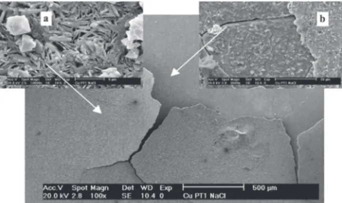
The SEM-EDXA observations revealed that S1 patinas formed both on copper and on bronze are composed by a bi-layered structure, whose images are presented in Figures 1 and 2, respectively. This kind of structure, as mentioned, is usual in natural and artificial patinas formed under
different conditions.3,5,7,11,12 The internal layer, apparently
more compact, presented high Cu and Cl contents. On the other hand, the external layer was very porous and presented faceted crystals with high Cu, O and N contents. While the internal layer formed on copper and bronze samples had approximately the same thickness, 2.7 mm and 2.4 mm, respectively, the external layer formed on bronze was thicker (7.9 mm) when compared to that formed on pure copper (3.8 mm), leading us to suppose that the solution is more aggressive to bronze, or that the internal layer formed on this metal is less protective.
XRD patterns of the S1 layers on copper revealed the
presence of gerhardite (Cu(NO3)(OH)3), nantokite (CuCl)
and cuprite (Cu2O). Conversely, on bronze, atacamite
(Cu2Cl(OH)3) was also observed, but cuprite was not
present. Combining EDXA and XRD results, one can conclude that, both on copper and on bronze, the internal layer is composed of nantokite, and the external layer is
mainly composed of hidroxynitrates. Robbiola et al,3 and
Mendoza et al.6 have observed the formation of a CuCl
layer at the bottom of layered natural and artificial patinas’
formed in soil-buried artifacts3 and in samples exposed to
marine environments.6 These layers were always
associated with higher corrosion rates when compared with other situations. In the case of the natural patinas, Robbiola
et al.3 verified that the CuCl layer had developed below
the original surface of the alloy. On the other hand,
Mendoza et al.6 detected that the longer the wetting time
of the patinas, the higher the corrosion rate.
A SEM surface image of S2 patina on copper is shown in Figure 3. One can see that there is two kinds of structures, which do not form superimposed layers as with S1. Instead, both structures grow from the substrate. EDXA have shown that the triangular crystals have high Cu and Cl contents, while the smaller ones have high O, Cu and Zn contents. The shape and amount of these smaller crystals are different on copper and on bronze, being powdery and in higher quantity when formed above the alloy, what can be ascribed
to the presence of Zn as an alloying element in the bronze, thus inducing an easier growth of Zn-containing compounds. No Zn compound, however, was identified in the XRD spectra. The only identified phases were gerhardite, nantokite and atacamite, both on copper and on bronze. One can suppose that Zn is dissolved in the nitrate, with just a small effect on lattice parameters, or is present
in some amorphous phase, as suggested by Robbiola et al.3
for Zn and Sn in soil-buried bronzes.
Corrosion behaviour of patina protected samples in NaCl solution
In order to better understand the patinas’ formation mechanisms, we have accompanied the evolution of the OCP of copper and bronze samples during three hours immersion experiments in S1 and S2 solutions. The results
are presented in Figure 4 together with part of the Pourbaix
diagrams for the Cu-Cl–-H
2O system proposed by Tromans
and Silva,20 for the activity of Cl– assumed as 0.67, which
corresponds to NaCl 1 mol L-1, and for the activity of
copper soluble species (as Cu2+) assumed as 0.01. Five
solid phases and two copper soluble species are described
in the system: CuCl, Cu, Cu2O, CuO, CuCl2.3Cu(OH)2,
Cu2+ and the complex [CuCl
2]
–. The lower and upper limits
of the CuCl domain, at pH values below those
corresponding to Cu2O, CuO and CuCl2.3Cu(OH)2
domains, are defined by the following equations:
CuCl– + e– → Cu + Cl
(E = 0.117 - 0.0591 log(0.67) = 0.127 VSHE) (1)
Cu+2 + Cl– + e–→ CuCl
(E = 0.564 + 0.0591 log(0.01×0.67) = 0.436 VSHE ) (2)
Figure 2. SEM images of the bronze sample with S1 treatment. a) Sur-face image, secondary electrons, original magnification 3500×. b) Trans-versal image, backscattered electrons, original magnification 5000×.
Although the patinas solutions are much more complex
than the Cu-Cl–-H
2O system reported in Figure 4, it is
interesting to observe that the OCP stabilizes in the CuCl domain in both solutions, even if the Pourbaix diagram is
recalculated considering the activities of Cu2+ and Cl– as the
nominal contents of these species in the patina solutions used in the present work, thus redefining the lower and upper limits
of this domain as 0.2 and 0.5 VSHE for S1 solution, and 0.1
and 0.6 VSHE for S2 solution, respectively (for Cu activity
assumed as 1 for both pure copper and bronze). However, the OCPs of the samples in the S1 solution are more anodic than in the S2 solution. This can be explained by the presence
of oxidizing species, Fe3+ ions and hydrogen peroxide, which
can lead to a faster precipitation of the CuCl layer for samples treated with this former solution. This would give origin to a compact bottom layer, and ultimately to bilayered structures, as observed in the SEM images. On the other hand, comparing the OCP curves for copper and bronze in the S1 solution, it can be verified that the potential of this latter sample quickly stabilizes in values below to those exhibited by the former, maybe explaining why the thickness of the patina bottom layer obtained in the bronze sample was slightly smaller than that formed on the copper sample. In accordance with our interpretation, SEM-EDXA observations of copper and bronze samples immersed in S1 for 25 minutes and published
elsewhere32 showed only CuCl crystals, whereas the samples
exposed to S2 showed two kinds of crystals, one of them rich in Zn, O and N, and the other rich in Cu and Cl.
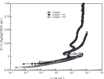
Figures 5 and 6 present a comparison between the
anodic polarization curves in the NaCl 0.5 mol L-1 test
solution for copper and bronze samples without and with S1 and S2 patinas, respectively. Three different regions compose the curves, in agreement with other results
published in the literature.18,19 The diagrams show that, in
the low anodic overpotential region, the presence of the patina layers does not cause any noticeable change in the anodic behaviour of the samples. Calculations performed at these overpotential regions have shown slopes near 60 mV
dec-1, irrespectively of the nature of the sample and of its
surface condition. According to several authors18-21,26,33 who
have investigated copper dissolution in acidic or neutral chloride-containing media, this slope characterizes a diffusion-controlled process ascribed to the diffusion of
the CuCl2– complex towards the bulk of the solution. On
the other hand the active-passive transition verified at potentials just above 0 V has been attributed to the
formation of a CuCl salt layer,18 which is in accordance
with the Pourbaix diagram presented in Figure 4(b). Different behaviours for copper and bronze samples were observed in the high overpotential regions of Figures 5 and 6: while copper samples presented potential activated currents, a diffusion-limited current is evident for bronze
samples. Lee and Nobe,19 using a rotating ring-disk
electrode, have determined the current due to the formation of cupric ions during the dissolution of copper in NaCl solution in a wide anodic potential region by setting the ring potential to a value where only cupric ions could be reduced. The shape of the reduction current curves obtained by these authors on the ring for high anodic overpotentials,
ascribed to the reduction of cupric ions introduced into the solution due to the dissolution of the Cu disk electrode, is very similar to that presented in Figure 6, so we can suppose that, in this anodic potential region, the bronze samples
dissolves only through the formation of Cu2+ ions. On the
other hand, for copper samples, the dissolution would take
place through the formation of Cu2+ and Cu+ species, being
similar to the overall anodic curves obtained by Lee and
Nobe for copper.19
Figure 7 presents Bode plots for a copper sample
immersed in 0.5 mol L-1 NaCl solution at selected times,
which were chosen when significant changes were observed in the diagrams, Nyquist diagrams are available as supplementary information (Figure S1). For short immersion times Nyquist diagrams are characterized by a diffusion controlled phenomenon in the medium (MF) to low (LF) frequency range, indicating a diffusion controlled phenomenon, as already suggested by the anodic polarization curves obtained after two hours of
immersion. However, the observation of the Bode phase angle diagram for this same immersion period shows the presence of a high frequency (HF) feature. For longer immersion periods, the HF capacitive loop further develops and the diffusive effect is displaced to lower
frequencies. Deslouis et al.,35 investigating the corrosion
of Cu in neutral aerated NaCl at the OCP, have verified the formation of two insoluble corrosion products CuCl
and Cu2O, the former being produced rapidly and the
latter being the main component of surface layers after long immersion periods in the test solution. The results presented in Figure 7 seem to be in accordance with this model. For short immersion times, 3 hours, no protective
effect of the Cu2O layer is observed, and the impedance
response is completely dominated by the diffusion of
the CuCl2– soluble complex, as shown in the Nyquist
diagrams. For this time span, the HF frequency feature could be likely ascribed to the initial development of the oxide layer. On the other hand, as the test continues,
the growth of the Cu2O layer would be the responsible
for the progressive development of the HF capacitive feature. Finally the LF diffusion tail observed for longer immersion periods would be likely ascribed to the diffusion of species through a porous oxide layer once it
becomes sufficiently compact.36
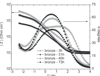
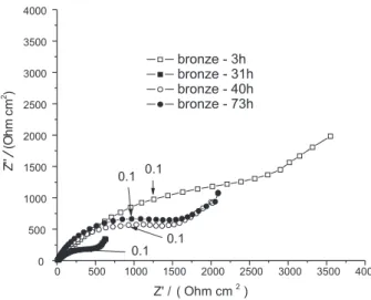
Figure 8 presents the Bode diagrams obtained for a
bronze sample in 0.5 mol L-1 NaCl solution at selected
times, corresponding Nyquist diagrams are available as supplementary information (Figure S2). Its behaviour is more complex than that exhibited by the copper sample, and is characterized by a decrease of the impedance up to 31 h of immersion, followed by its increase. Moreover, the impedances exhibited by this sample are smaller than those presented by the copper one, which is consistent
Figure 5. Anodic polarization curves for copper with and without patina layers (solution NaCl 0.5 mol L-1, with pH=5.6). Scan rate 0.1 mV s-1.
Figure 6. Anodic polarization curves for bronze with and without patina layers (solution NaCl 0.5 mol L-1 with pH 5.6). Scan rate 0.1 mV s-1.
with the previously presented hypothesis that the top porous patina layer is thicker when formed on this former metal due to enhanced surface activity.
For short immersion times, i.e., three hours, Nyquist
diagram (Figure S2) is characterized by a wide and depressed capacitive loop. The Bode phase-angle plot associated with this loop, presented in Figure 8, is very broad, indicating the interaction of several time constants, which can be likely ascribed to the complex composition of the alloy. However, after 31 hours of contact with the aggressive electrolyte, the impedance diagrams assumes a similar shape to that exhibited by the copper sample, and the same corrosion mechanism is assumed for both metals for longer immersion times.
Figure 9 shows the Bode diagrams for copper covered with S1 patinas (Nyquist diagrams corresponds to Figure S3 in the supplementary information). Two time constants are clearly defined throughout the whole experimental period. During the first two days of immersion (until 40 h), there is an augmentation of the impedance of the sample, and an increase of the capacitance associated with the HF loop. This can be likely due to pore blocking by corrosion products and/or thickening of the patina layer. However, for immersion times longer than 40 hours, this trend is reversed, with a decrease in the impedance, which becomes very similar to that presented by bare copper, even though presenting smaller values. At potential values near the ones used to perform the EIS measurements presented in this work, as indicated in the anodic polarization curves, the stable soluble species formed
between copper and chloride ions is [CuCl2]–,20 and there
are no thermodynamic conditions for CuCl precipitation.
Zhang et al.7 have shown that the runoff rates of Cu from
naturally patinated copper during continuous rain events
was superior to its corrosion rate, indicating that some chemical dissolution takes place when patinated samples are exposed to bulk electrolyte. Accordingly, at the CuCl layer/electrolyte interface, the nantokite can be chemically
dissolved according to the reaction below:18
CuCl + Cl–→ CuCl
2
– (3)
Based on the assumptions above, we can suppose that the chemical dissolution of the CuCl internal layer would diminish the impedance of the sample for longer test periods, which, ultimately, would result in the collapse of the patina layer. Indeed, Figure 10 shows that, at the end of the experimental period, only the internal patina layer has been dissolved, while the top layer remained almost undamaged. It must be emphasized that, under normal atmospheric exposure conditions, the complete dissolution of the patinas shall not occur, since the time they remain exposed to an electrolyte, like during rain events, is relatively short, and the tendency of the patina layer is to become thicker with time as pollutants and airborne
particles are incorporated into its composition.7
Bode diagrams with immersion time for bronze treated with S1 are presented in Figure 11, the same features as for copper samples, Figure 9, are observed. The evolution of impedance, however, is slower than with copper, and as evidenced in the Nyquist plots (available as Supplementary Information Figure S4) the lower frequency loop is more depressed, which is coherent with the higher thickness of the outer patina layer on bronze, already mentioned. As with copper, a decrease in the impedance is observed at the end of the three-day immersion test, corresponding to the collapsing of the patina layer. However, no great diminution of the impedance response associated with this process was observed. This can be likely explained by the less protective
Figure 8. Bode diagrams for bare bronze after different times of contact with NaCl 0.5 mol L-1.
power of the patinas formed on this sample, which would
allow the progressive formation of the Cu2O layer underneath
the patina layer. In this way, when the patina layer collapses, due to the dissolution of the CuCl layer, a more compact oxide layer would be already present on the sample surface resulting in higher impedances.
Figures 12 and 13 show Bode diagrams for copper and bronze covered with S2 patinas (Nyquist diagrams are available as supplementary material, Figures S4 and S5, respectively). For both samples, at short immersion times,
very low phase angles, close to 25o, are observed,
corresponding to a predominantly resistive response, associated with small impedance values. This can be ascribed to the very porous structure of this patina layer on copper and on bronze, leading to a fast access of the electrolyte to the base metal, which would be enhanced by the dissolution of the CuCl. For longer immersion times, the copper sample presents a behaviour very similar to that exhibited by the bare sample, with a diffusion-controlled phenomenon being observed after approximately one day of immersion, and an
increase of the HF phase angle for longer immersion periods. On the other hand, bronze samples presented a slower increase of the impedance with immersion time. The EDXA of the surface of this latter sample after the end of the experimental period of 72 hours have shown strong peaks related to copper and oxygen, indicating the formation of an oxide layer, which would explain the observed response.
Conclusions
We have investigated the electrochemical behaviour of two different nitrate-based patinas produced on copper and bronze samples at room temperature by the dabbing procedure. The results of the microstructural characterization have shown that the patinas’ morphology and microstructure are dependent on the oxidizing power of the solutions, with bilayered structures being formed in the solution containing
oxidizing agent, like Fe3+ ions and hydrogen peroxide, and
monolayered structures formed in the less oxidizing solution. On the other hand, the layers compositions were only
Figure 10. SEM secondary electrons image for copper + S1 patina after three days of immersion in NaCl 0.5 mol L-1. Original magnifications of
100× in the general view, 10000× in detail a (external layer) and 3500× in detail b (internal layer and substrate).
Figure 11. Bode diagrams for bronze coated with the S1 patina after different times of contact with NaCl 0.5 mol L-1.
Figure 12. Bode diagrams for copper coated with the S2 patina diagrams after different times of contact with NaCl 0.5 mol L-1.
dependent on the patinas’ solution, being independent of the nature of the substrate.
The results of the anodic polarization curves have shown that, at the open circuit potential, the samples dissolution presents the same rate-determining step in the studied medium irrespectively of their nature — copper or bronze — and of the nature of the patina layer, in accordance with the classical mechanism corresponding
to the diffusion of a soluble complex.26,27 EIS experiments
have confirmed this mechanism, and, in addition, have evidenced the dependence of the corrosion of patinas covered samples on the structure and compactness of these layers. Therefore, the samples covered with the monolayered structure corroded very fast, while those covered with the bilayered patinas presented a good corrosion response while the bottom layer was still compact. In both cases the dissolution of nantokite by the electrolyte seems to be the main process taking place at the patina layers which contributed to their collapse.
As a final remark we can say that the results obtained in this work have shown a high degree of accordance between morphological and impedance measurements, showing that this latter technique can be a powerful tool for studying the behaviour of artificial patina layers, and can be used to help understanding the corrosion mechanism of ancient copper and bronze artefacts.
Supplementary Information
Supplementary data are available free of charge at http://jbcs.sbq.org.br, as PDF file.
Acknowledgments
The authors are thankful to CNPq and CAPES (Brazilian Federal research supporting agencies) and to FAPESP (São Paulo State research supporting agency) for project supporting and grants.
References
1. Hughes, R.; Rowe, M.; The Colouring, Bronzing and Patination
of Metals; 1st ed., Watson-Guptill Publications: New York, 1991.
2.Virtanen, J.; Aromaa, J.; Forsén, O.; Korpinen, T.; 15th
International Corrosion Congress, Granada, Spain, 2002. 3. Robbiola, L.; Blengino, J. M.; Fiaud, J. M.; Corros. Sci. 1998,
40, 2083.
4. Giumlia-Mair, A.; Surf. Eng. 2001, 17, 217.
5. Balta, I. Z.; Robbiola, L.; Proceedings of the NACE 2003 (National Association of Corrosion Engineeers), Ottawa, Canada, 2003.
6. Mendoza, A.R.; Corvo, F.; Gomez, A.; Gomez, J.; Corros. Sci. 2004, 46, 1189.
7. Zhang, X.; He, W.; Wallinder, I.O.; Pan, J.; Leygraf, C.; Corros. Sci. 2002, 44, 2131.
8. Noli, F.; Misaelides, P.; Hatzidimitriou, A; Pavlidou, E.; Mater. M.; Mater. Chem. 2003,13, 114.
9. Beldjoudi, T.; Bardet, F.; Lacoudre, N.; Andrieu, A.; Adriaens, A.; Constantinides, I.; Brunella, P.; Surf. Eng. 2001, 17, 231. 10. Constantinides, I.; Adriaens, A.; Adams, F.; Appl. Surf. Sci.
2002, 189, 90.
11. Angelini, E.; Bianco, P.; Zuchi, F. In Progress in the Understanding and Prevention of Corrosion; Costa, J. M.; Mercer, A. D., eds.; Institute of Materials, The University Press: Cambridge, 1993.
12. Wadsak, M.; Constantinides, I.; Vittiglio, G.; Adriaens, A.; Janssens, K.; Schreiner, M.; Adams, F. C.; Brunella, P.; Wuttmann, M.; Mikrochim. Acta2000,133, 159.
13. Cicileo, G. P.; Crespo, M. A.; Rosales, B. M; Corros. Sci. 2004, 46, 929.
14. Bastidas, J. M.; López-Delgado, A.; López, F. A.; Alonso, M. P.; J. Mater. Sci. 1997, 32, 129.
15. Bastidas, J. M.; López-Delgado, A.; López, F. A.; Alonso, M. P.; J. Mater. Sci. 1997, 16, 776.
16. Schlesinger, R.; Klewe-Nebenius, H.; Bruns, M.; Surf. Interface
Anal. 2000, 30, 135.
17. Fitzgerald, K. P.; Nairn, J.; Atrens, A.; Corros. Sci. 1998,40, 2029.
18. Benedetti, A.V.; Sumodjo, P. T. A.; Nobe, K.; Cabot, P. L.; Proud, W. G.; Electrochim. Acta1995, 40, 2657.
19. Lee, H. P.; Nobe, K.; J. Electrochem. Soc.1983, 133, 2035. 20. Tromans, D.; Silva, J. C; Corrosion1997, 53, 16. 21. Tromans, D.; Silva, J. C; Corrosion1997, 53, 171.
22. Brunoro, G.; Gilli, G.; Nagliati, R.; Surf. Technol., 1984, 21, 125. 23. Brunoro, G.; Lwaguzzi, G.; Luvidi, L.; Chiavari, C.; British
Corrosion Journal2001, 36, 227.
24. Tommesani, L.; Brunoro, G.; Garagnani, G. L.; Montanari, R.; Volterri, R.; Revue d’Archeometrie 1997,21, 131.
25. Morales,J.; Fernandez, G. T.; Esparza, P; Gonzáles, S.; Salvarezza, R. C.; Arvia, A. J.; Revue d’Archeometrie, Costa, J. M.; Mercer, A. D., eds.; Institute of Materials, The University Press: Cambridge, UK, 1993, pp. 1458-1462.
26. Moreau, A.; Electrochim. Acta1981,26, 497. 27 Moreau, A.; Electrochim. Acta 1981, 26, 1609.
28. Itagaki, M.; Tagaki, M.; Watanabi, K.; Corros. Sci. 1996, 38, 1109.
29. Souissi, N.; Bousselmi, L; Khosrof, S.; Triki, E.; Materials
and Corrosion, 2003, 54, 318.
32. Bendezú, R. H.; M.Sc. Dissertation, Escola Politécnica da Universidade de Sao Paulo, Sao Paulo, Brazil, 2004. 33. Dhar, H. P.; White, R. E.; Burnell, G.; Corwell, L; Griffin, R.
B.; Darby, R.; Corrosion1985, 41, 317.
34. Diard, J.-P.; Le Canut, J.-M.; Gorrec, B. L.; Montella, C.;
Electrochim. Acta1998, 43, 2485.
35. Deslouis, C.; Mengoli, G.; Musiani, M.M.; Tribollet B.; J. Appl. Electrochem. 1988, 18, 374.
36. Deslouis, C.; Tribollet, B.; Mengoli, G.; Musiani, M.M.; J. Appl. Electrochem. 1988, 18, 384.
Received: March 27, 2006 Web Release Date: October 19, 2006
0103 - 5053 $6.00+0.00
S
u
p
p
le
m
e
nta
ry
Inf
o
rm
a
ti
o
n
*e-mail: [email protected]
EIS and Microstructural Characterization of Artificial Nitrate Patina Layers Produced
at Room Temperature on Copper and Bronze
R. del P. Bendezú H., R. P. Gonçalves, A. C. Neiva and H. G. de Melo*
Departamento de Engenharia Química, Escola Politécnica, Universidade de São Paulo, Av. Prof. Luciano Gualberto, Travessa 3, 380, Cidade Universitária “Armando de Salles Oliveira”
05508-900 São Paulo-SP, Brazil
Figure S4. Nyquist diagrams for bronze coated with the S1 patina after different times of contact with 0.5 mol L-1 NaCl. Corresponding to Bode
diagrams presented in Figure 11 of the main text.
Figure S2. Nyquist diagrams for bare bronze after different times of con-tact with 0.5 mol L-1 NaCl. Corresponding to Bode diagrams presented in
Figure 8 of the main text.
Figure S1. Nyquist diagrams for bare copper after different times of con-tact with 0.5 mol L-1 NaCl. Corresponding to Bode diagrams presented in
Figure 7 of the main text. Figure S3.different times of contact with 0.5 mol L Nyquist diagrams for copper coated with the S1 patina after-1 NaCl solution. Corresponding
Figure S5. Nyquist diagrams for copper coated with the S2 patina dia-grams after different times of contact with 0.5 mol L-1 NaCl.
Correspond-ing to Bode diagrams presented in Figure 12 of the main text.
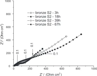
Figure S6. Nyquist diagrams for bronze coated with the S2 patina after different times of contact with 0.5 mol L-1 NaCl. Corresponding to Bode