Observations of Corrosion Product Formation and Stress Corrosion Cracking on Brass
Samples Exposed to Ammonia Environments
Raul Davalos-Monteiro1*
Received: January 31, 2018; Revised: June 08, 2018; Accepted: November 08, 2018
The corrosion product formation and the stress corrosion cracking of brass in different ammonia environments have been observed and characterized. Optical and scanning electron microscopy techniques were used to analyze the corrosion phenomena on the systems. The testing methodology was designed to investigate the variables affecting stress corrosion cracking behaviour, these parameters were: stamp geometry, immersion time, Cl- concentration, pH, copper ions concentration, exposure to
vapour/ liquid. From this investigation, stress corrosion cracking of brass was shown to occur most severely in ammonia vapour. The increase of the amount of ammonia and copper ions in the form of copper sulphate was found to increase the corrosion of the brass samples.
Keywords: SCC, Ammonia, Corrosion products, Brass.
*e-mail: [email protected].
1. Introduction
Stress corrosion cracking (SCC) of brass in ammonia Stress corrosion cracking (SCC) have long occurred for various types of brass and copper-base alloys in aqueous ammonia solutions. SCC is a form of environmentally assisted cracking that occurs as a result of internal strains. It was known that brasses stored in a dry and clean atmosphere, although carrying high internal strains, cracked only after a long time; while a damp atmosphere was especially active in producing such cracking, particularly if it carried ammonia vapor from decaying organic matter1. SCC of brass
was first identified when brass cartridge cases used by the British Army in India were found to suffer from cracking in ammonia from the decay of horse urine2. The effect was
termed ‘season cracking’ because it occurred during the rainy season and, secondly, because the cracks resembled the cracks in seasoned wood2.
Several major disasters have involved stress corrosion cracking, including the rupture of high-pressure gas transmission pipes, the explosion of boilers, and the destruction of power stations and oil refineries 2. While SCC of brass remains a
problem, the occurrence is reduced by the substitution of plastics for many applications previously dominated by brass. Past experience has also indicated that cracking was more frequent in brasses carrying a higher percent of zinc (Zn). The identified two modes of cracking are intergranular and transgranular, for which extensive systematic studies were initiated by Mattsson's work, published in 1961 1.
Brass pipe manufacturing and associated defects In this investigation, segments of a brass pipe are examined for their stress corrosion cracking behavior. For this reason, the manufacturing process for brass piping and
the associated microstructural effects are examined in this section. Brass pipes may be forged or extruded due to their excellent hot working properties, good machinability, high strength and corrosion resistance. Hot extrusion of brass is the main processing method by which pipes are formed. Brass billets at 595-995˚C are extruded through a die at ram speeds ranging from 50 to 400 mm/s 3.
Defects such as surface cracks, tears or delamination may occur during processing if the die is insufficiently or excessively heated, if the ram speed is too high, or if there is high friction between the billet and die walls4. Intergranular
cracking may also occur due to local cooling of impurities at grain boundaries. Residual stresses occur within the extruded part by non-uniform flow patterns or by mechanical working and increase its susceptibility to stress corrosion cracking in specific environments. In addition to these stresses that may already be present in the material, stamping also induces residual stresses where corrosion can occur preferentially. Lead is often added to brass (0.10% in Cu30Zn) to increase machinability3.
Solutions of Aqueous Ammonia
For the present work, five different ammonia based solutions have been established for testing brass samples. Brass has been shown to corrode in aqueous solutions of ammonia, sodium nitrite, citrates, sulfur dioxide and sulfate solutions4. The key features of the solutions are given in this
section to compare the differences in solution composition, concentration and pH as they relate to the corrosion behavior of brass. Four out of five solutions contain ammonium ion compounds such as NH4SO4, NH4OH, (NH4)2SO4, while one is a pure ammonia solution. The common species present in all solutions is the ammonium ion. The following chemical equations describe the method by which brass may corrode in the presence of ammonia5.
(Oxidation of copper cuprous complex ions)
(Oxidation of zinc cuprous -> complex ions)
(Formation of cupric complex ions)
(Formation of cuprous oxide)
In solutions containing cuprous complex ions Cu(NH3)2+,
the rate of zinc dissolution will be faster than copper dissolution and a “dezincification layer” with high tensile stress forms5.
Induced tensile stresses encourage SCC. In solutions where the pH is raised, by the addition of ammonium hydroxide, for example, OH- suppresses the reaction forming cupric
complex ions and that of zinc oxidation so that a black, passive cuprous oxide film forms. Acidifying the solution, by the addition of H2SO4, for example, reduces the rate of reactions promoting the formation of a dezincification layer and a passive Cu2O film forms5. Other species that are
present in solutions used in this experiment are copper ions (Cu2+) and chloride ions (Cl-); the last one is considered as
the most aggressive species. It is expected that the addition of NaCl to solution will increase the severity of corrosion.
SCC of brass occurs in the presence of dissolved copper. This is because copper dissolves to form a complex ion in solution, which acts as an oxidizer to promote the cathodic reduction reaction6. It can be inferred that test solutions
containing a high amount and availability copper ions in the form of copper sulphate will promote more severe SCC. An oxide film or tarnish forms at some critical concentration of copper, which is approximately 2.8 g/l, and reduces the rate of corrosion but not of stress corrosion cracking6.
Visual inspection enables the determination of compounds that may be present in solution. For example, a blue-ish colour indicates the presence of copper sulphate in solution. The concentration of each compound influences the colour intensity. Solution transparency indicates a low relative concentration of the compound, while increased intensity of the colour present in solution indicates a high relative concentration of the compound. Ammonia, containing no Cu2+, is clear, while high pH solutions containing 0.05 g/l
CuSO4 are dark blue. Solutions that contain CuSO4 but are diluted by the presence of (NH4)SO4 or NaCl are light blue.
2. Experimental
Stress corrosion cracking of brass in ammonia solutions was carried out with guidelines given by ASTM standard G37-98: Standard Practice for Use of Mattsson's Solution of pH 7.2 to Evaluate the Stress Corrosion Cracking Susceptibility of Copper-Zinc Alloys7. This test is performed to determine
the degree of stress corrosion cracking of brass under one or more specific stress conditions.
Seven test pieces of brass were given. Samples were stamped with the letter ‘D’ and a number, if applicable, on the top. Samples were stamped with a ‘T’ or a ‘U’ on the bottom to determine the effect of pre-straining and letter geometry on the corrosion behaviour of the sample.
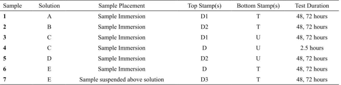
Five ammonia solutions, whose compositions are given in Table 1. The samples were exposed to the solutions for durations of 2.5 hours to 72 hours at room temperature (25˚C).
Samples were hung in beakers containing 60 mL of each solution. Fishing line was threaded through the drilled holes in the sample so that they hung with about 1 cm of the sample left out of solution. The rest of the container had a small amount of air in it. Samples 1-6 were immersed up to the stamp at the top of the sample. Sample 7 was suspended above the solution. A summary of the test conditions for each sample is given below.
The samples were removed from the solution, placed on clean tissues and examined by visual inspection and optical microscopy. The samples were then cleaned in 1M sulphuric acid to remove the corrosion product, rinsed in deionized water, and dried with tissues. They were then re-examined visually, by optical microscopy and by scanning electron microscopy (SEM). For samples that were expected to undergo stress corrosion cracking (samples 2, 3, 5, 6, and 7), thinner samples were supplied, placed in their respective solutions for 72 hours and examined by similar methods.
The variables affecting stress corrosion cracking behavior that were investigated in these experiments:
• Stamp Geometry (Samples: 1, 2, 6, 7 & 3, 4, 5) • Immersion time (Samples: 3 & 4 )
• Cl- Concentration (Samples: 3 & 5)
• pH (Samples: 1& 2)
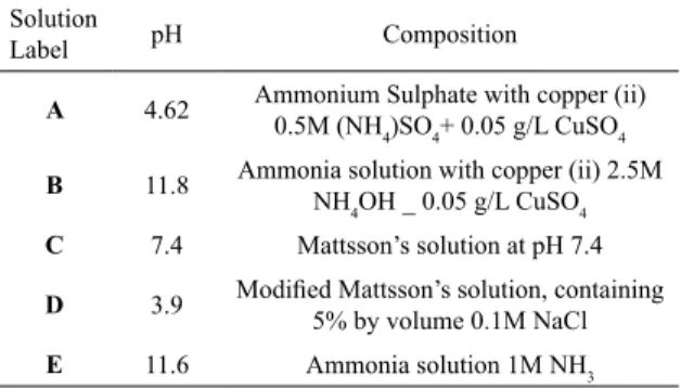
Table 1. Experimental solution composition
Solution
Label pH Composition
A 4.62 Ammonium Sulphate with copper (ii) 0.5M (NH4)SO4+ 0.05 g/L CuSO4
B 11.8 Ammonia solution with copper (ii) 2.5M NH4OH _ 0.05 g/L CuSO4
C 7.4 Mattsson’s solution at pH 7.4
D 3.9 Modified Mattsson’s solution, containing 5% by volume 0.1M NaCl
E 11.6 Ammonia solution 1M NH3
Zn
4
NH
3Zn NH
3 42
e
2
$
+
Q
V
++
-Cu NH
O
H O
NH
Cu NH
OH
2
4
2
2
3 2 12 2 2 3 3 4 2
$
+
+
+
+
+ +-Q
Q
V
V
Cu NH
OH
Cu O
NH
H O
2
3 2+
2
$
2+
4
3+
2+
-Q
V
Cu
+
2
NH
3$
Cu NH
3 2+
e
+
• Copper Concentration (Samples: 2 & 6 ) • Exposure to vapor/ Liquid (Samples: 6 & 7 )
3. Results
Evidence of SCC that can be differentiated by optical microscopy images are presented in Figure 1, Figure 2, Figure 3, Figure 4, Figure 5, Figure 6, and Figure 7 below.
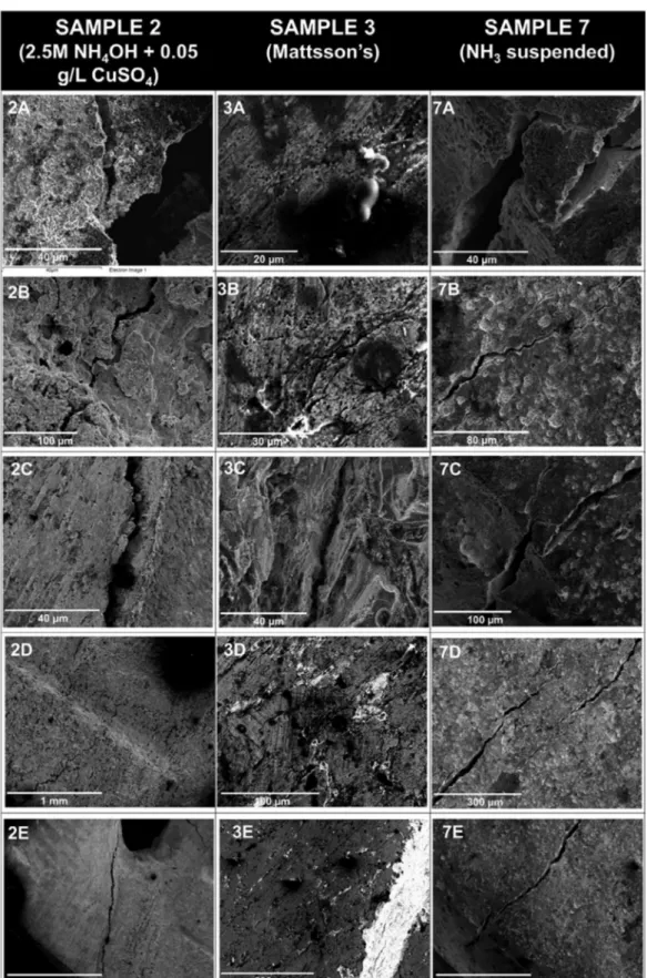
SCC detected on the exposed samples by the use of SEM is presented in Figure 8.
4. Discussion
Brass Corrosion Behavior in Ammonium Sulphate with Copper and Ammonia Solution with Copper (Samples 1&2)
There was a significant visual difference between Sample 1 and Sample 2. Sample 1, submerged in 0.5 M (NH4)SO4 + 7.9 E-4 M CuSO4, was essentially not corroded
while Sample 2, submerged in 2.5 M (NH4)OH + 7.9 E-4
M CuSO4, was totally corroded with corrosion products on the brass surface. The immersed surface the corrosion product was gray and silver and the non-immersed surface corrosion product was white, blue, and black. This is due to a combination of cuprous oxide and complex cuprous and
cupric ions. When oxides/corrosion products were removed in pickling solution, a reddish brown surface layer of copper could be seen on the samples8.
(copper plating on pickled brass surface)
On the left side of SEM Image 2A in Figure 8, striations are shown where cleavage may have occurred. However, most of the cracks in the SEM images were indicative of intergranular SCC rather than transgranular.
Effect of Ammonia Concentration in Brass Corrosion The main difference between these two tests is the ammonium compounds. The first is ammonium sulphate and the second is ammonium hydroxide. The concentration of the solution with ammonium hydroxide is five times more concentrated than the solution of ammonium sulphate. Due to this difference in concentration in the ammonium compounds, brass Sample 2 is more corroded than the brass in Sample 1 9.
The remarkable difference in the corrosion products in brass in Sample 2 was due to the concentration of ammonium in the gas part of the beaker. The volatility of ammonium and the concentration of ammonia in the gas part of the beaker increased and created a very corrosive environment, which has affected the non-immersed part of the brass. The submerged part of the brass corroded as well, and it showed a very notable dezincification, and due to this dezincification, a gray film of zinc hydroxide and zinc oxide was covering the entire submerged surface.
The sulphate present in the solution in test 1 may have acted as an inhibitor for the corrosion process, however, the lower pH (discussed in the subsequent section) is more likely the cause for reduced corrosion and susceptibility to SCC.
Effect of pH in Corrosion of a Brass Sample in Ammonia and Ammonium Environments
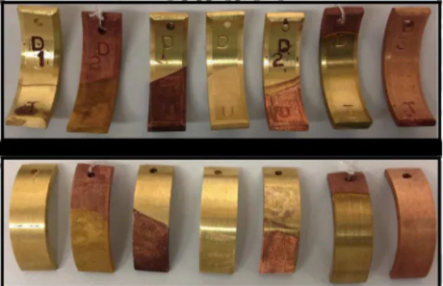
Figure 1. Front (top) and back (bottom) images of brass samples 1 through 7 (left to right) after corrosion testing in ammonia solutions
Figure 2. Front (top) and back (bottom) images of brass samples 1 through 7 (left to right) after corrosion testing in ammonia solutions and cleaning in 1M sulphuric acid pickling solution.
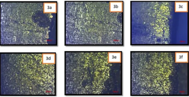
Figure 3. Optical microscopy images of exposed sample2 that presented clear evidence of cracking on the surface.
Cu
2+
H O
2+
2
e
$
2
Cu
+
2
OH
-From the results of the test 1& 2, the effect of pH in brass corrosion with ammonium and ammonia environments was identified. Based on the E-pH diagrams in Cu-Zn alloys created by Tromans, it can be established that a higher pH (more than 10) brass suffers from corrosion in ammonium solution. Since Sample 1 was exposed to a solution pH of 4,62 and Sample 2 was exposed to a solution pH of 11,8 the corrosion in brass Sample 2 is more aggressive than that of Sample 1, as shown in Figure 1.
The explanation of corrosion of brass at high pH is based on a phenomenon called dezincification. Dezincification is the selective loss of zinc from brass by the electrochemical reaction between zinc and aqueous solutions. Based on the results of the solubility of zinc in aqueous media published by10. At pH between 8-9, the solubility of zinc increases,
but increasing the pH from 9-14 decreases the solubility of zinc and it forms corrosion products or passive scale layers. Since the pH of Solution B in test 2 was 11.8, the process of dezincification occurred and affected the brass but a scale layer of zinc products also formed because the solubility of zinc in the solution was not high in basic pH10.
Moreover, lower pH environments reduce the thickness of the dezincification layer and therfore its associated tensile stresses, reduces the susceptibility of SCC.
Optical Microscopy of SCC of a brass sample submerged in ammonia solution with copper 2.5 M (NH4)
OH + 7.9 E-4M CuSO 4
Figure 3 shows microscopic images of cracks on the brass sample submerged in 2.5 M (NH4)OH + 7.9 E-4 M CuSO4 solution.
Image 2A shows a crack who started in the edge located in the bottom of the sample very close to the right corner.
As it can be seen from the Figure 3, the crack initiates at the edge of the sample and propagates through the center of the sample in a perpendicular direction. The reason for cracks in the edges is the cold working applied in the middle of the sample that induces tension in the edges of the sample. Another reason for cracks occurring along the edges is the sample cutting process, which could influence the residual stress on the sample edges.
In image 2C some small cracks are visible in the sample that initiate from a scratch in a perpendicular to the scratch in the left side near the edge. A scratch is part of the cold work and it cans initiate cracks. In image 2D we can see a very deep crack from the bottom of the sample in the left side. In this image, the shape of the crack is notable, as is the perpendicular propagation from the edge to the center of the sample.
Scanning Electron Microscopy (SEM) of SCC of a brass sample submerged in ammonia solution with copper 2.5 M (NH4)OH + 7.9 E
-4M CuSO 4
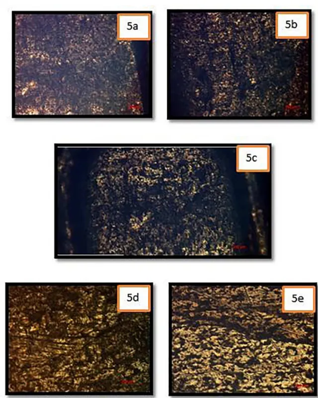
Figure 5. Optical microscopy images of exposed sample 5 that presented clear evidence of cracking on the sur-face.
Corrosion Behaviour of Brass Samples in Mattsson’s Solution, Modified Mattsson’s Solution (Samples 2, 3, & 5) In this section the different results that have been observed in Samples 3, 4, and 5 are discussed. Based on the solutions these samples have been immersed in, which are displayed on Table 2, two major observations are analyzed. First, the influence of the immersion time could be analyzed as the
solutions have no substantial variation on its components. Second, the effects of the presence of Cl- ions on the
showed no substantial corrosion. The first phenomenon that applies in these kinds of solutions is dezincification. From the galvanic series it is known that zinc is highly reactive so it could be dissolved from alloys when is in contact with corrosive environments such as ammonia. Sample 3 presents a dark red film on the corroded surface which is presumed to be cuprous oxide (Cu2O) as Cu ions will react in solution and deposit on the metal surface11. Sample 5 shows less
corrosion as brass edges were noticed among the corroded surface. Corrosion on Sample 5 shows a shiny copper color which could be the result of dezincification.
In order to verify the existence of cracks, the samples were taken to an optical microscope. From Figure 4 and Figure 5, dezincification is shown to take place on the surface of the samples; surface morphology on both pieces of metal corroborates this statement. Much and more evident cracks were found in Sample 3 (Figure 4) than on Sample 5 (Figure 5). The later also presents some cracks that were found near the stamped letters such as Figure 3 2C, coming out from scratches as shown in Figure 3 2d and a couple near the edges (Figure 3: 2a, 2b). It seems to be that sample Sample 3 has more cracks spread over its whole surface than sample 5. Here is where Cl- must be playing a role on
enhancing or inhibiting SCC. According to12, chloride ions
will have an inhibiting effect on SCC of brass. One of the protective mechanisms that could be acting is that in which the adsorption of Cl- interferes with the adsorption of the
aggressive ammonia species12. It has also been reported
that chloride could slow down crack propagation; however, care should be taken as this species is also known for enhancing crack tip dissolution12. From these observations
it could be said that Cl- has slow down crack propagation on Sample 5. In addition, it can be inferred that some specific Cl- concentration should be attained to achieve the desired
behavior of chloride on brass.
For Sample 3, SEM images shown in Figure 8 show the cracking mechanism. From what it can be noticed mainly on images 3D and 3B (Figure 8) is that cracks seem to be following an intergranular path. This means that grain boundaries of the material are affected in such a way that they allow crack propagation. It has been reported for samples under pH 7.4 Mattsson’s solution, that intergranular cracking will take place following a certain process. First, micro pits will form on dislocations and Cu2O and Cu will be produced. Then, Cu2O and Cu films will grow and act as a cathode enhancing brass corrosion. Finally, dislocations will be forced into grain boundaries thus forming cracks11.
Intergranular cracking should be expected when using pH 7.4 Mattsson’s solution.
In modified Mattsson’s solution, the presence of chloride may cause pitting corrosion to dominate as the local corrosion process instead of SCC. This was not seen as no SEM images were observed for Sample 5 in modified Mattsson’s solution and pits were not visible in the optical images.
Figure 6. Optical microscopy images of exposed sample 6 that presented clear evidence of cracking on the sur-face.
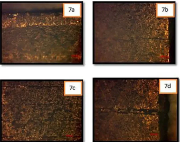
Figure 7. Optical microscopy images of exposed sample 7 that presented clear evidence of cracking on the sur-face.
The sample that was left for the shortest period of time (2.5 hours) did not show any corrosion product; the immersed surface just changed from shiny to dull. The samples that remained in the solutions for extended periods of time (Sample 3 and 5) developed corrosion products on their surfaces. The turquoise color on Sample 3 (Figure 1) and in the solution after exposure, for example, is copper sulphate. From these observations it can be said that samples need to remain in solution for a considerable period of time in order to appreciate stress corrosion cracking; however, it should be taken into account that SCC depends on environment, materials and stress, so variation in any of these components would alter the results5.
Regarding the presence of chloride ions in solution, Samples 3 and 5 are used to define the effect of this species in brass. Sample 3 was immersed in Mattsson’s solution, which is composed of CuSO4 + (NH4)2SO411. Sample 5 was immersed
Table 2. Table of Experiments
Sample Solution Sample Placement Top Stamp(s) Bottom Stamp(s) Test Duration
1 A Sample Immersion D1 T 48, 72 hours
2 B Sample Immersion D2 T 48, 72 hours
3 C Sample Immersion D1 U 48, 72 hours
4 C Sample Immersion D U 2.5 hours
5 D Sample Immersion D2 U 48, 72 hours
6 E Sample Immersion D T 48, 72 hours
7 E Sample suspended above solution D3 T 48, 72 hours
Corrosion Behaviour of Brass Samples in 1M Ammonia (Samples 6 & 7)
Samples 6 and 7 were immersed in 1M ammonia (NH3) at a pH of 11.6. In the presence of ammonia vapour, brass samples were shown to form a dark gray corrosion product that uniformly covered the entire specimen. This film is cuprous oxide (Cu2O) and the process by which it is formed is called tarnishing. On the brass sample, reduction of oxygen occurs, accompanied by the oxidation of copper to form cuprous complex ions, mentioned in section 1.4. Cuprous complex ions may then reduce to form cupric complex ions. Ammonia is present in higher concentrations in its pure vapour form than it is in aqueous solution, which is why corrosion took place for samples in the presence of ammonia vapour but not aqueous, liquid ammonia.
From the optical and SEM micrographs, it is apparent that corrosion of the non-immersed part of Samples 6 and of all of Sample 7 is among the most severe of all of the samples. A layer of moisture on the surface of the brass sample increases the ratio of metal surface area to solution, and can contain a high concentration of copper ions and facilitate oxygen access to the solution to reduce cuprous ions to cupric ions6. However, corrosion product buildup on
the surface of the sample may have also lowered the ability for the crack to interact with the environment. If the latter occurred, the diffusion of ionic species to the crack tip to promote chemical conversion of metal to metal oxide is less likely and, thus, crack propagation does not occur as rapidly. It seems as though Sample 2, which was exposed to ammonia and copper sulphate, and Sample 5, exposed to an environment containing chloride, may have suffered from more SCC than Samples 6 and 7.
Immersion of Sample 6 into NH3 for 48 hours caused the solution to change from clear to pale blue. This was due to the oxidation of Cu to Cu2+ or Cu(NH
3)
2+ into solution (as
described in section 1.4). The colour of the solution above which Sample 7 was suspended remained clear because the ions could not be transferred to the solution.
Images 7A and 7C of Figure 8 show the formation of intergranular microcracks, which propagates around a grain of the brass specimen. When a Cu2O film develops on the sample, it prevents ongoing crack propagation along slip planes that is characteristic of transgranular cracking11.
Dislocation pile up due to pre-straining, as well as inherent vacancies and impurities that are present on grain boundaries encourage crack propagation along these sites instead. Cu2O surface films that develop along grain boundaries also contain defects that enable diffusion of corrosion product to the underlying metal and accelerate corrosion and crack propagation11.
Crack branching occurred in Sample 7, as shown in Figure 7, image 7B. Branching may have occurred because the sample possessed a higher stress. The different points of failure, or branches, are driven by a combination of chemistry, microstructure and stress. In Image 7D two cracks are seen separated by a plane of brass lattices. It was suggested that these cracks may meet below the sample surface. Cracks also occurred frequently along the edge of the brass sample, where geometrical discontinuity and a high-energy free surface promote crack propagation.
Effect of Pre-straining and Induced Stress by Stamping on SCC
Stress is required for failure by SCC to occur in a material. This stress must exceed failure stress threshold of that material to enable failure to occur. Components contain defects as a result of design processes like cold working. Macroscopically, cold working may create geometric discontinuities whose shapes create stress concentration on some part of the material. If this stress exceeds the stress threshold, SCC will occur once the material is exposed to environment under a particular service13. The stress required to cause a crack is
usually below the macroscopic yield strength and is tensile in nature14. In fracture mechanics, the stress intensity factor,
K, which is a function of the crack tip geometry, helps to determine what governs crack tip propagation.
K = σ (π a) 1/2, where σ: applied stress, 2a: depth of crack
(stress intensity factor)
Microscopically, applied stress results in dislocation movement to form slip steps, which are preferred sites of SCC15.
grain boundary dislocation movement and created localised strains within the sample.
Cracks were observed as lines penetrating the sample in the direction perpendicular to the direction of the machining lines, often extending from the corners of sample, from stamped letters, and around the sample edges. In the images of Sample 2 in Figure 8, cracks are shown extending from the hole where strings were used to suspend the samples in solution and from the impressed letter H. Image 2d in Figure 3, and 6c and 6d in Figure 6 show cracking on the tips of the samples and across the engraved letter edges. These were observed after the samples were immersed in Mattsson’s solution and are a result of stress concentration at the stamped area and tip of the samples causing dislocation of grain boundaries and tension around the tip of the sample16.
Also, the anodic reaction occurring at the edge of the sample causes dissolution of the metals.
The engraved letters on the samples created a compressive stress around the area engraved on the sample which caused inhomogeneous distribution of dislocation movement within the microstructure with a tendency to segregate at grain boundaries, thereby resulting in local strain gradients16. The
shape (depth and sharpness) of the letter engraved on the samples determined the direction stress will propagate and raised the stress that led to SCC of brass.
Comparsions, similarities and correlations within the parameteres applied
Stamp geometry, immersion time, Cl- concentration, pH,
copper ions concentration, exposure to vapor/ liquid were the parameters applied to brass alloy samples.
A similarity founded in this investigation is the suceptibility of brass in ammonia enviroments related with time. As degradation process corrosion is mostly time-depending, hence the higher the exposure time of brass alloys in ammonia environments the higher the susceptibility to present SSC effects. A very markable consistency on this time behaviour is the comparision with sample 4 in which the exposure time was only 2.5 hours and in which a lower degradation could be obseverd in relation with samples exposed more than 24 hours.
An interesting chemical similarity is the dezincification process in which it happened in practically all the tests. The zinc part of the brass alloy tends to dissolve in all the ammonia enviroments that were tested. A double behaviour related with the pH of the solution can be notable from tests 1 and 2, in which the electrochemical process of zinc dissolution in the aqueous environment also has proctetive behaviour due to the low solubility of it; as a result of this is the production of a scale layer tha slow down the corrosion process.
In terms of vapour/liquid phases is clear that the vapour phase of ammonia creates an extremely corrive environment for brass alloys. The main difference with immersed tests lays on the evident dependednt relationship with the nature
of the environment (pH, concentrations) the exposure time, and visibly the mechanical stresses.
5. Conclusions
From this investigation, stress corrosion cracking of brass was shown to occur most severely in ammonia vapour.
The amount of ammonia and of copper ions in the form of copper sulphate was found to increase the corrosion of the brass samples.
Over 48 hours, thick samples did not exhibit cracking, while thin samples did. Macroscopically, these cracks occurred along geometric discontinuities such as edges of the sample and of the stamped lettering.
Microscopically, it was shown that transgranular and intergranular cracking of the samples occurred. The type of microscopic cracking was dependent on the amount and type of corrosion product present, the accessibility of oxidizing agents, or copper ions in solution, the pH of the environment and the amount of residual stress in the brass sample. These will either promote diffusion of ionic speciesinto the sample or emphasize the presence of defects within the sample. Slip dissolution and dezincification were the underlying mechanisms causing SCC.
6. Acknowledgements
The author is grateful to SENESCYT-Ecuador for providing financial support covered by the Top Universities Scholarship 2015.
7. References
1. Seleet MS. Electrochemistry of Stress Corrosion Cracking of Brass. [Dissertation]. Ames: Iowa State University; 1986.
2. Nugent M, Khan Z. The effects of corrosion rate and manufacturing
in the prevention of stress corrosion cracking on structural members of steel bridges. The Journal of Corrosion Science and Engineering. 2014;17:16.
3. Davis JR, ed. Copper and Copper Alloys. Materials Park: ASM International; 2001.
4. Davis JR. Forging and Extrusion. In: Davis JR, ed. Copper and Copper Alloys . Materials Park: ASM International; 2001. p. 220-222.
5. Guo XJ, Gao KW, Qiao LJ, Chu WY. The correspondence between susceptibility to SCC of brass and corrosion-induced tensile stress with various pH values. Corrosion Science. 2002;44(10):2367-2378.
6. Davis JR. Stress-Corrosion Cracking. In: Davis JR, ed. Copper and Copper Alloys . Materials Park: ASM International; 2001. p. 419-429.
8. Procter RPMN, Stevens GN. The formation of cuprous oxide
films on α-brass stress-corrosion fracture surfaces. Corrosion Science. 1975;15(6-12):349-539.
9. Tromans D. Copper and zinc equilibria in concentrated ammonia solutions: Relevance to stress corrosion cracking of alpha-brass.
Corrosion Science. 1997;39(7):1307-1319.
10. Zhang Y. Dezincification and Brass Lead Leaching in Premise
Plumbing Systems: Effects of Alloy, Physical Conditions and Water Chemistry. [Thesis]. Blacksburg: Virginia Polytechnic Institute and State University; 2009.
11. Takano M, Shimodaira S. The mechanism of stress corrosion cracking in the brass-ammonia system. Corrosion Science. 1968;8(2):55-60, IN1-IN3, 61-6.
12. King F, Greidanus G, Jobe D. Dissolution of Copper in Chloride/ Ammonia Mixtures and the Implications for the Stress Corrosion Cracking of Copper Containers. Chalk River EACL - Atomic Energy of Canada Limited; 1999.
13. Kandil FA, Lord JD, Fry AT, Grant PV. A Review of Residual Stress Measurement Methods. A Guide to Technique Selection. Teddington: National Physical Laboratory; 2001.
14. Paxton HW, Procter RP. The Effect of Machining and Grinding
on the Stress-Corrosion Cracking Susceptibility of Metals and Alloys. Dearborn: ASTME; 1969.
15. Takano M, Shimodaira S. Mechanisms of intergranular stress corrosion cracking in 70 Cu-30 Zn alloy. Transactions of the Japan Institute of Metals. 1966;7(3):193-198.
16. Ulaganathan J, Newman RC. The role of local strains from prior
cold work on stress corrosion cracking of α-brass in Mattsson's