*e-mail: [email protected]
Influence of the Testing Gage Length on the Strength, Young’s Modulus
and Weibull Modulus of Carbon Fibres and Glass Fibres
Luiz Claudio Pardinia*, Luis Guilherme Borzani Manhanib a
Centro Técnico Aeroespacial, Instituto de Aeronáutica e Espaço, Divisão de Materiais – AMR, 12228-904 São José dos Campos - SP, Brazil
b
Centro Técnico Aeroespacial, Instituto Tecnológico de Aeronáutica, Departamento de Física, 12228-900 São José dos Campos - SP, Brazil
Received: January 21, 2002; Revised: October 04, 2002
Carbon fibres and glass fibres are reinforcements for advanced composites and the fiber strength is the most influential factor on the strength of the composites. They are essentially brittle and fail with very little reduction in cross section. Composites made with these fibres are characterized by a high strength/density ratio and their properties are intrisically related to their microstructure, i.e., amount and orientation of the fibres, surface treatment, among other factors. Processing pa-rameters have an important role in the fibre mechanical behaviour (strength and modulus). Cracks, voids and impurities in the case of glass fibres and fibrillar misalignments in the case of carbon fibres are created during processing. Such inhomogeneities give rise to an appreciable scatter in properties. The most used statistical tool that deals with this characteristic variability in properties is the Weibull distribution. The present work investigates the influence of the testing gage length on the strength, Young’s modulus and Weibull modulus of carbon fibres and glass fibres. The Young’s modulus is calculated by two methods: (i) ASTM D 3379M, and (ii) interaction between testing equipment/specimen The first method resulted in a Young modulus of 183 GPa for carbon fibre, and 76 GPa for glass fibre. The second method gave a Young modulus of 250 GPa for carbon fibre and 50 GPa for glass fibre. These differences revelead differences on how the interaction specimen/testing machine can interfere in the Young modulus calculations. Weibull modulus can be a tool to evaluate the fibre’s homogeneity in terms of properties and it is a good quality control parameter during processing. In the range of specimen gage length tested the Weibull modulus for carbon fibre is ~ 3.30 and for glass fibres is ~ 5.65, which indicates that for the batch of fibres tested, the glass fibre is more uniform in properties.
Keywords: carbon fibres, glass fibres, Young modulus, Weibull modulus.
1. Introduction
A considerable progress over the past three decades has been made in the reinforcement technology, but as many other things, they were not created equally. Many factors contribute to the variability in properties, and the key fac-tors that influence mechanical properties are raw material and processing conditions. Carbon fibres, for instance, are mainly manufactured by spinning termoplastic fibres, pre-dominantly polyacrilonitrile and pitch, which under con-trolled drawing and pyrolysis are converted to stiff oriented
distribution strength at short gauge lengths and fibre elastic modulus. On the other hand, composite properties are highly influenced by fibre/matrix bonding.
After processing, statistic control or qualification pro-grams applied to reinforcing fibres are based on evalua-tion of mechanical properties. Tensile strength is a straight-forward measurement on fibres. Although filaments can be as thin as ~ 7.5 µm in diameter they can be easily fitted in paper tab and tensile tests can be performed in a simple way. On the other hand, their inherent brittleness cause difficulties to measure deformation by standard strain-sens-ing devices, such as strain-gages, extensometers, etc, or by other more sophisticated and expensive techniques such as optical methods. So, the first aim of this work is to use two methodologies to calculate the modulus. The first one is based on the system compliance, as stated in the ASTM D 3379M1, and the second one takes into account the
ri-gidity of the equipment where fibres are tested. In the lat-ter method the results of the tensile test reflect the inlat-terac- interac-tion between the testing equipment and specimen under test2. Both methods used the same set of data for
calcula-tions. The literature reports for high strength carbon fibre a tensile strength of 3.0 GPa and a Young modulus of 230.0 GPa3. For glass fibres an average tensile strength of
2.2 GPa and Young modulus in the range of 60.0 GPa to 90.0 GPa are reported.
Unlike many other physical parameters such as elastic modulus, density, etc, filament strength is a statistical pa-rameter which can not be fully described by a single value. The most used statistical tool to describe the variability in strength for materials is the Weibull distribution. The Weibull modulus is not a material constant, but gives a good indica-tion of how homogeneous the material is.
2. Materials and Experimental
In the present work the carbon fibre studied was a PAN-based high strength 400 dtex type, manufactured by Hexcel Carbon Fibres, under the trade name of AS4-GP. E-glass type fibres were provided by Owens Corning Ltda, 750 dtex. Both fibres were tested according to the ASTM D 3379M Standard. The fibres were cut in dissimilar positions from the fibre tow assuring a random selection of single filaments. Gage lengths of 25 mm, 50 mm, 75 mm and 100 mm were prepared by moulting in a paper support tab, as shown in Fig. 1. The testing speed was 2.5 mm/min, graphic paper speed was 200 mm/min. The testing machine used during the work was an Instron 1131, and a load cell of 50 gf was used. For carbon fibres the full scale testing was set at 20 gf and for glass fibre the full scale testing was set at 50 gf. At least twenty-five specimens were tested from each kind of fibre.
The tensile test gives us a load as a function of extension
curve up to failure. Tensile strength was calculated as fol-lows:
σ = F/A (1)
where F = tensile force to failure (N), A = average cross section filament area (m2).
The carbon fibre modulus was calculated following two procedures. The first is described in ASTM D 3379M Stand-ard. The procedure suggests that indicated compliance is first calculated as follows:
Ca = (I/P) × (H/S) (2)
where I = total extension for the straight line section of load/time curve extrapolated across full chart scale (mm), H = crosshead speed (mm/s), P = full scale force (N),
Figure 1. Support tab for testing fibre filaments according to ASTM D 3379M1.
Figure 2. Graphic representation of a tensile test of fibre single filament.
filament
S = chart speed (mm/s). The true compliance is then calcu-lated as:
C = Ca – Cs (3)
where C = true compliance (mm/N), Cs = system compli-ance (mm/N).
The Young’s Modulus is calculated as a corrected value by the equation :
E = L/(C×A) (4)
where E = Young modulus (GPa), L = specimen gage length (mm), C = True compliance (mm/N), and A = average fila-ment area (mm2).
The second method to correct the Young modulus value followed a procedure which takes into account the interac-tion between equipment/specimen during testing, as de-scribed by Guimarães2. According to this method the
equip-ment and the specimen are considered as two springs in series, as shown in Fig. 3, one representing the testing ma-chine having a rigidity (Km), and the other one representing the specimen having a rigidity proporcional to the Young´s modulus, as follows2 :
A L E m K s K . 1 1 1 + = (5)
where Ks is the rigidity of the system, L is the specimen length, E = Young´s modulus, A = cross section area of the specimen.
At the onset of the test, the specimen is in the elastic regime and the slope of the load/extension curve can be used to calculate Ks, as follows:
Ks = tg (θo) (6)
The angle θo is measured, as indicated in Fig. 2, and Young´s modulus can be calculated by the Eq. 7:
+ = ⇒ − = − − − o o m o o m A L E K tg E A L tg
K ( ) ( )1 1 1.
o 1
1
o θ
θ (7)
where Lo and Ao are the initial gage length and cross section area of the filament specimen.
If θo is known, and “tg θo” is plotted as a function of Lo/Ao, values for Km and E can be obtained. Correction of the elastic modulus is necessary because the testing equip-ment can exhibit a dependency where the equipequip-ment re-sponse during testing is dependent on the sample gage length. This dependency is manifested as an elastic defor-mation contribution from the testing equipment.
The Weibull modulus from each set of fibre tested was determined at different gage lengths. This was accomplished by plotting Eq. 84:
o m m
P .lnσ .lnσ
1 1 ln
ln = −
− (8)
where P is the probability of failure, m is the Weibull shape parameter, σ is the tensile strength and σo is the scale pa-rameter.
The Weibull modulus is obtained by plotting ln [ln(1/(1-P))] as function of ln σ. The probability from mean position corresponding to the i-th observation is given by P = i/N+i, where N is the number of samples. The Weibull parameter (m) is obtained by linear regression.
3. Results and Discussions
Initially, Hookean behaviour was assumed for glass and carbon fibres in the calculation of Young’s modulus. Ta-ble 1 show results for tensile tests for carbon fibre. It shows a trend where the higher gage length of the fibre filament is the lower the tensile strength obtained is. This trend has been also reported by other researchers, and it is related to the increase in flaw population when higher gage length is used for testing5. Table 2 shows the results obtained for
ten-sile tests for glass fibres and a similar behaviour was found for these fibres when compared to carbon fibres.
All fibres failed in a brittle manner by exhibiting a sharp drop in strength after ultimate failure stress. Mean values for tensile strength for carbon fibres and for glass fibres were close to each other. The tensile strength reported in
Figure 3. Representation of the testing system equipment/speci-men in the elastic regime. K = testing machine spring constant,
the literature for both glass fibres and carbon fibres are close to the value found in this work, 2.70 GPa and 2.38 GPa respectively.
Figure 4 shows a plot of tensile strength as a function of gage length for glass fibres. Glass fibre tensile strength tends, although not regularly, to a decrease in strength with an increase in the gage length tested. On the other hand, Fig. 5 shows that an increase in the carbon fibre gage length leads to a decrease in the tensile strength. The decrease in tensile strength with increasing gage length tested is mainly asso-ciated with an increase in flaw population5.
As it could be expected, a large difference was found in Young’s modulus values for glass fibres (90 GPa) and for carbon fibres (233 GPa). This is due to their atomic struc-ture6. Essentially, PAN-based carbon fibres are
non-graphitizing with a turbostratic (irregular) organisation of the graphitic layer planes, and the most realistic model of the structure consists of a complex fibrillar structure three-dimensionally interlinked forming crystallites which enclose sharp-edged voids7. In E-glass type fibres the presence of
elements such as Ca, Na and K tends to break up the regular network of the three-dimensional covalent bonded tetrahe-dral formed in the presence of silicon, at the centre, and oxygen at the corners. This can cause regions of inhomoge-neities in fibre structure at different levels and hence causes variation in strength8.
Results from Table 1 and Table 2 indicate that for the onset of fracture, the energy necessary to break chemical
Table 1. Properties of the carbon fibre at various specimen gage length.
Specimen gage Tensile strength Extension at Calculated strain Young´s modulus
length (mm) (GPa) break (mm) (%)* (GPa)*
25 2.90 ± 0.97 0.325 1.318 220.0
50 2.70 ± 0.72 0.5631 1.126 240.0
75 2.66± 0.87 0.8351 1.113 240.0
100 2.54 ± 0.80 1.0882 1.088 233.0
Average 2.70 ± 0.15 — 1.1612 ± 0.10 233.0 ± 9.4
* assuming ideal Hookean behaviour.
Table 2. Properties of glass fibres at various specimen gage length.
Specimen gage Tensile strength Extension at Calculated strain Young´s modulus
length (mm) (GPa) break (mm) (%)* (GPa)*
25 2.58 ± 0.40 0.83 3.30 78.00
50 2.27 ± 0.50 1.19 2.40 95.60
75 2.43 ± 0.48 1.60 2.50 97.00
100 2.18 ± 0.40 2.38 2.40 91.60
Average 2.38 ± 0.19 - 2.65 ± 0.43 90.50 ± 8.70
* assuming ideal Hookean behaviour.
Figure 4. Tensile strength as a function of sample gage length for glass fibres.
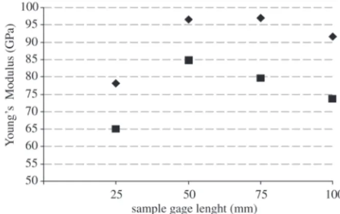
bonds in glass fibres is twice as high as the energy neces-sary for carbon fibres. Table 1 and Table 2 also show results for Young’s modulus by assuming Hookean behaviour for both fibres. The results showed that glass fibre Young’s modulus is higher than the ones found in the literature. For carbon fibres, the results for Young’s modulus agreed well with those from the literature. As stated earlier in this work, carbon and glass filaments are very thin and, as a conse-quence, it is not possible to attach strain-gages to these fi-bres. As a result, Young’s modulus obtained can be mis-leading by assuming the ideal Hookean behaviour. So, in the next sections it is present two methods for Young’s modu-lus calculations, as following :
• Calculation of Young’s modulus by ASTM 3329M method, and
• Calculation of Young’s modulus by the rigidity method (interaction testing equipment/specimen)
Calculation of Young’s Modulus by ASTM D 3329M Method
By using Eq. 4 the corrected Young’s modulus can be calculated. The true compliance (C) is obtained by
subtract-ing the system compliance (Cs), taksubtract-ing it at zero gage length in Fig. 6 for carbon fibres, and in Fig. 7 for glass fibres, from the indicated compliance (Ca) for each gage length, using Eq. 2. The Fig. 8 shows plots for Young’s modulus assuming ideal Hookean behaviour and the corrected Young’s modulus according to ASTM D 3329M for carbon fibres and Fig. 9 shows equivalent plots for glass fibres.
According to ASTM D 3329M testing method, the cor-rected Young’s modulus found for carbon fibres was ~183.0 ± 6.6 GPa, and ~75.7 ± 8.4 GPa for glass fibres, Table 3 and Table 4, respectively. For high strength carbon fibre a Young’s modulus of ~220 GPa is reported in the lit-erature, the correction gives an underestimated value, al-though no information is given about testing conditions3.
This result also indicates that correction by ASTM D 3329M gives a more conservative result. For glass fibres, however,
Figure 6. Graphical plot for the system (testing equipment) com-pliance for carbon fibres.
Figure 7. Graphical plot for the system (testing equipment) com-pliance for glass fibres.
Figure 8. Young’s modulus for carbon fibres. (u) assuming ideal Hookean behaviour, (g) corrected Young’s modulus according to ASTM D 3329M.
the corrected result agreed well with the value given by lit-erature, where it is reported a Young’s modulus of ~70 GPa. As a result, by assuming ideal Hookean behaviour for both carbon and glass fibres, the results for Young’s modulus are overestimated at any gage length tested.
Calculation of Young’s Modulus by the Rigidity Method (Interaction Testing Equipment/Specimen)
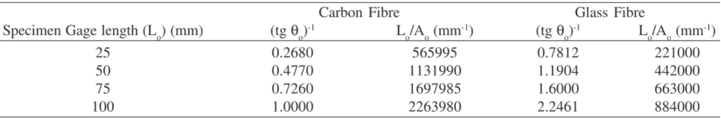
This approach for modulus calculation needs initiallly the value of the angle θo from the load as a function of ex-tension curve for each gage length of fibre tested, as exem-plified in Fig. 2, and also the gage length/filament cross section (Lo/Ao) ratio. Table 5 shows results for these param-eters for both carbon and glass fibres. The graphical plot from the results showed in Table 5 are in Fig. 10 for carbon fibres (Ao = 4.78.10-11 m2) and Fig. 11 for glass fibres
(Ao = 1.13.10-10 m2).
According to this method (rigidy method), the corrected
Table 5. Results for (tg θo)-1 and gage length/cross section area (L
o/Ao) for each gage length tested, for carbon fibres and glass fibres.
Carbon Fibre Glass Fibre
Specimen Gage length (Lo) (mm) (tg θo)-1 L
o/Ao (mm
-1) (tg θ o)
-1 L
o/Ao (mm -1)
25 0.2680 565995 0.7812 221000
50 0.4770 1131990 1.1904 442000
75 0.7260 1697985 1.6000 663000
100 1.0000 2263980 2.2461 884000
Figure 11. Graphical plot of equation 7 taken from experimental data from Table 5, for glass fibres.
Figure 10. Graphical plot of Eq. 7 taken from experimental data from Table 5, for carbon fibres.
Table 3. Calculations for the corrected Young’s modulus for car-bon fibres, according to ASTM D 3329M.
Specimen gage Ca Ci Ecorreted
length (Lo) (mm) (mm/N) (mm/N) (GPa)
25 3.2500 3.2489 174.2
50 5.9795 5.9785 189.3
75 9.1020 9.1010 186.5
100 12.4816 12.4806 181.4
Average ⇒ 182.9 ± 6.6
Table 4. Calculations for the corrected Young’s modulus for glass fibres, according to ASTM D 3329M.
Specimen gage Ca Ci Ecorreted
length (Lo) (mm) (mm/N) (mm/N) (GPa)
25 3.9000 3.3969 65.1
50 5.7209 5.2178 84.7
75 8.8367 8.3336 79.6
100 12.5145 12.0115 73.6
Average ⇒ 75.7 ± 8.5
Young’s modulus is given by the inverse of the angular co-efficient. The Fig. 8 showing carbon fibre behaviour indi-cates that angular coefficient is equal to 4.10-7. Thus, the
value of the corrected Young’s modulus for the carbon fi-bre, obtained by rigidity method, is equal to 250 GPa. For glass fibre the angular coefficient taken from the plot of Fig. 9 is 2.10-6 results in a corrected Young’s modulus equal
agreed well with the value for Young’s modulus found as-suming a linear elastic behaviour during tensile tests (~233 GPa), and also agreed with the value given in the literature8.
The value of testing machine rigidity (Km) was calcu-lated from Eq. (5). The value of Km depends on geometrical parameters of the specimen, Young’s modulus and on angle (θ) of the load as function of displacement for the speci-men. For carbon fibre the Young’s modulus is much higher than for glass fibre and the angle (θ) of the load/displacement curve is steeper giving rise to a testing machine rigidity of 3.8 kN/m. For glass fibres the Young’s is lower than for carbon fibres and the angle (θ) of the load/displacement curve is also lower than that for carbon fibres giving rise to a higher testing machine rigidity (Km = 13 kN/m). Thus, the INSTRON testing machine used in this work is almost three times stiffer for testing glass fibres than for testing carbon fibres.
Weibull Modulus
The tensile strength for both carbon fibre and glass fi-bre obtained in the present work were evaluated under con-stant volume, i.e., a set of samples had a concon-stant gage length. The Weibull modulus for both carbon and glass fibres were calculated for each gage length tested according to Eq. 8. The plots for carbon fibres at each gage length tested is shown in Fig. 12. The equation of the line draw through the points has the form “y = ax + b” , where “a” represents the Weibull modulus4,9.
The Weibull parameter “m” can be regarded as a flaw frequency distribution factor4. High values of “m” indicates
that flaws are evenly distributed throughout the material, whatever they are plentiful or not, and hence strength is nearly independent of the length. Low values of “m” indi-cated that flaws are fewer and less evenly distributed, caus-ing greater scatter in strength. All graphical plots of Weibull distribution for carbon fibres, obtained in the present work, showed that “m” falls in a narrow range (m = 3.0 - 3.6), indicating that the latter assumption, fewer flaws less evenly distributed, is the case for carbon fibre. Flaws in carbon fibres are mainly represented by pores. The carbon fibre of the type used in this work is characterized by a mean pore diameter of about 5.5 nm, and a broad ultramicropore dis-tribution in the range of 2 nm to 40 nm, and a pore volume of ~0.2%10. These figures indicate that strength statitics of
carbon fibre is mainly controlled by small flaw population. The Weibull theory also states that for a material with homogeneous quality having a near unimodal distribution of flaw size the value of “m” should be the same at all sam-ple length, and the mean value of strength at the different lengths should increase with decrease in length. The car-bon fibre used in this work followed this trend, which indi-cates that it has an unimodal distribution of flaw size.
De-spite the high scatter in the tensile strength values for car-bon fibre (~30%), commonly found for this kind of mate-rial, the narrow range of “m” parameter indicates that it has an homogeneous quality.
Tagawa11 investigated statistical distributions of the
ten-sile strength in carbon fibres for 10 years period using ex-PAN carbon fibres and mesophase pitch carbon fibre. In his work a Weibull parameter of 4 was found, irrespective of the carbon fibre precursor and strength level. Tensile strength in the carbon fibres almost follows a single modal Weibull distribution, suggesting a single fracture mechanism. The fracture mechanism of carbon fibres is mainly due to misorientation of the graphite crystal layers around some inclusions and voids, which is assumed as a defect control-ling mechanism.
Glass fibre shows a different picture from the carbon fibre behaviour, as shown in Fig. 13. The Weibull modulus varies at each gage length tested indicanting that mechani-cal properties of glass fibre is not homogeneous from bath to bath. It must be pointed out that surface defects are the cause of premature failure in fibres and these defects can also appear during fibre handling. Weibull modulus for glass fibre has a high value in relation to the Weibull modulus for carbon fibre. This indicates that the scatter in mechanical properties for the glass fibre is lower than that for carbon fibre, despite of the fact that glass fibre Weibull modulus exhibits a near constant value.
The average fracture stress is not a constant but depends on the specimen gage length. This change follows the Eq. 912:
m / 1 1 2 2 1 L L = σ σ (9)
Thus, just one Weibull modulus could be calculated from the set of fibres tested. Considering the average value of carbon fibre Weibull modulus (3.28) and the specimen gage length of L1 = 25 mm and average values for tensile strength (σ1 = 2.90 GPa), the resulting σ2 tested at L2 = 100 mm gage length would be 1.90 GPa, which is the lowest value for carbon fibre tensile strength.
Considering the average value of glass fibre Weibull modulus (5.76) and the specimen gage length of L1 = 25 mm and average values for tensile strength (σ1 = 2.58 GPa), the resulting σ2 tested at L2 = 100 mm gage length would be 2.03 GPa, which is in the lower bound for glass fibre tensile strength.
4. Conclusion
in structural composites, a high strenght carbon fibre and a glass fibre. In the range of specimen gage length tested, the tensile strength of glass fibres is within the range of 1.8-3.0 GPa (average 2.38 GPa) and tensile strength for carbon fibres is within the range of 1.8 – 3.8 GPa (2.70 GPa).
Because such fibres have small diameter (~10 µm) it is not possible to use conventional strain-gages sensors in order to measure deformation and to calculate directly the Young’s modulus. Thus, two methods were used to evalu-ate Young’s modulus. The first followed a procedure de-scribed in ASTM D 3379 Standard, and the second fol-lowed a procedure which takes into account the interac-tion between testing equipment and specimen under test, named the rigidity method. By using the ASTM D 3379M standard, the calculated Young’s modulus for carbon fi-bres is ~183 GPa and for glass fifi-bres is ~76 GPa. These values are lower than the Young’s modulus calculated
as-suming ideal Hookean behaviour for both fibres. The ASTM D 3379 method underestimates the carbon fibre Young’s modulus in relation to literature values. On the other hand, by using the rigidy method a Young’s modu-lus of 250 GPa and 50 GPa was found for carbon fibres and glass fibres, respectively. In relation to literature val-ues the ASTM D3379M standard underestimates the car-bon fibre Young’s Modulus, and the rigidy method under-estimates the glass fibre Young’s Modulus. The differences in Young’s modulus calculations from both methods can be explained by the fact that ASTM D3379M standard takes only the system rigidity (specimen/testing machine) into account, while the rigidity method distinguishes the system rigidity from the testing machine rigidity. As a consequence, testing machine rigidity can have a propor-tionally lower influence on testing stiffer ceramic fibres, e.g. carbon fibres, which reflects in the Young’s modulus calculations.
Reinforcing fibres have defects generated during processing and from handling, such as ultramicropores, fi-bril misalignments and impurities, which are the main source for crack initiation and failure in fibres. These defects cause either lower and scattered strenght values. Weibull modu-lus for carbon fibre was in the range of 3.00 a 3.55 and for glass fibres in the range of 4.74 and 6.58 . So, the scatter in strength for carbon fibre is a bit higher than for glass fibres, although carbon fibre has more homogeneous quality than glass fibre have. In other words, carbon fibres have more flaws than glass fibres but they are evenly distributed throughout the length of the filament.
Acknowledgments
The authors express their thanks to FAPESP, Proc. 00/04359-3,and to Prof. Flaminio Levy Neto for useful dis-cussions.
References
1. ASTM D 3379 – Tensile Strength and Young’s Modulus for High-Modulus Single-Filament Materials
2. Guimarães, J.R.C.; Chawla, K.K., Metalurgia, v. 34, n. 249, p. 549-552, 1978.
3. Matthews, F.L.; Rawlings, R.D. Composite Materials:
Engineering and Science, Chapman & Hall, 1994. 4. Weibull, W. J. Appl. Mechanics, v. 18, p. 293-297, 1951. 5. Hitchon, J.W.; Phillips, D.C. Fibre Science and
Technol-ogy, v. 12, p. 217- 233, 1979.
6. Belitskus, D. Fiber and Whisker Reinforced Ceramics for Structural Applications, Marcel Dekker, Inc. 1993. 7. Johnson, D.J. Carbon Fibres: Manufacture, Properties,
Structure and Applications, Ch. 6, Induction to Carbon Science, Ed. Harry Marsh, Butterworths & Co Ltd., 1989. 8. Hull, D.; Clyne, T.W. An Introduction to Composite
Figure 15. Weibull plots for tensile strength offor glass fibres for all test specimen length.
Materials, Cambridge University Press, 2nd Ed., 1996.
9. Pina, S.R.O.; Piorino-Neto, F.; Pardini, L.C., 23th Biennial
Conference on Carbon, Newcastle-upon-Tyne-UK, 1997. 10. Lee, J.S.; Kang, T. J. Carbon, v. 35, n. 2, p. 209-216, 1997.
11. Tagawa, T.; Mujata,T. Materials Science and Engineer-ing, v. A238, p. 336-342, 1997.