DOI: http://dx.doi.org/10.1590/2446-4740.0637
*e-mail: [email protected]
Received: 10 August 2014 / Accepted: 19 October 2015
A bilinear elastic constitutive model applied for midpalatal suture
behavior during rapid maxillary expansion
Larissa Carvalho Trojan Serpe*, Estevam Barbosa de Las Casas, Ana Cláudia Moreira Melo Toyofuku, Libardo Andrés González-Torres
Abstract Introduction: This study aims to evaluate the inluence of the biomechanical behavior of the midpalatal suture (MPS) during the rapid maxillary expansion (RME) when modeled by the Finite Element Method. Methods: Four simulation alternatives are discussed and, for each analysis, the suture is considered as a functional unit with a different mechanical behavior: (i) without MPS elements, (ii) MPS with Young’s modulus (E) equal to 1 MPa, (ii) MPS with E equal to 0.01 MPa and (iv) MPS with bilinear elastic behavior. Results: The stress analysis showed that, when MPS is not considered in the model, stress peaks are reduced in magnitude and their distribution is restricted to a smaller area when compared to the model with the inclusion of MPS (E=1 MPa). The increased suture stiffness also has a direct inluence on MPS displacements after 30 expander activations. Conclusion: The consideration of the MPS in RME computer models inluences greatly the calculated displacements between the suture bone ends, even as the stress levels in maxillary structures. Furthermore, as proposed for the described model, the elastic bilinear behavior assigned to MPS allows coherent prediction of stresses and displacements results, being a good representation for this suture overall behavior.
Keywords: Midpalatal suture, Biomechanics, Finite element analysis, Rapid maxillary expansion.
Introduction
Biomechanical studies using the Finite Element Method (FEM) are common in Orthodontics (Holberg and Rudzki-Janson, 2006; Provatidis et al., 2008; Serpe et al., 2014; Wang et al., 2012). Recent computational studies have evaluated stresses and displacements generated in the craniofacial complex due to rapid maxillary expansion (RME). This therapeutic technique basically consists of separating the bone ends of the suture (MPS) using a palatal expander – a device attached to the posterior teeth and supported or not on palatal mucosa.
According to clinical data, a total displacement of 7 mm applied by an expansion screw in 8 to 14 years old patient results in a 2.54 mm increase in the
distance between the central incisor crowns, 36%
of the expansion screw opening (Ballanti et al., 2010). In another study with patients of the same age span (Weissheimer et al., 2011), the authors noted a “V” shaped suture expansion after RME, with the anterior maxillary wide basis, representing around
50% (32.7-54.7%) of the applied displacement by
the expansion device (8 mm) in the anterior region
and 36% (27.2-39.2%) in the posterior region.
The percentage of the total applied displacement that effectively is transferred to the MPS is one
parameter used to access the effectiveness of the proposed procedure.
Biomechanical studies (Gautam et al., 2007; Iseri et al., 1998; Jafari et al., 2003; Lee et al., 2009; Provatidis et al., 2008) attempted to improve the understanding of this phenomenon and to evaluate how this orthodontic therapy affects other regions of the skull. But most of them considered only linear elastic constitutive model for the analysis, which potentially can result in a model that provides an improved representation of the expansion process. Iseri et al. (1998) used a tridimensional (3D) model of the skull with thick shell elements and considered all materials as linear elastic. Simulating RME, an expansion of 5 mm was applied on each half of the expander (overall 10 mm) and, as a result, a greater displacement in dentoalveolar area was obtained, which gradually diminished in upper structures as nasal cavity. High von Mises stress levels were observed in the jaw bone regions near the canines and molars (184.62 and 56.11 MPa, respectively), in the lateral wall of the inferior nasal cavity, in the nasal and the zygomatic bone. The highest stress peak was in the pterygoid plates of the sphenoid bone, near the skull
basis (723 MPa). Using the same material properties
and 10 mm of expansion, Jafari et al. (2003) observed
the following results: 5.31 mm of maximum lateral
displacement in the region of central incisors; 1.08 mm of maximum displacement for anterior bone region, located in the anterior edge of the nasal septum. The nasal bone, nasomaxillary suture, nasofrontal suture and anterior border of the frontal process of the zygomatic bone experienced von Mises stresses
up to 321 MPa. In the frontal, parietal, temporal
and occipital bones the stress levels were between 0 to 40 MPa.
Gautam et al. (2007) also evaluated the stress
distribution along the facial sutures with inite element
analysis using tetrahedral solid elements with the aim to improve accuracy when compared with shell elements. Maximum von Mises stress were found along the frontomaxillary, nasomaxillary, and frontonasal sutures, followed by zygomaticotemporal and zygomaticosphenoid sutures. Tensile and compressive strains were observed along the same suture, as is the case for zygomaticotemporal, zygomaticofrontal and zygomaticomaxillary sutures.
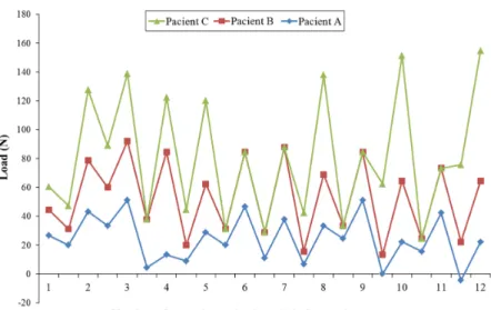
Isaacson and Ingram (1964) observed in a clinical study a phenomenon of stress relaxation that occurs in the craniofacial complex between successive activations of the expander screw, as seen in Figure 1. Also considering this phenomenon, and based on data obtained from a Finite Element (FE) study that compared displacement and stress distribution for different models, Provatidis et al. (2007), showed that the most accurate model for the study of RME treatment must contain all skull, complete maxillary dentition, including MPS and consider the phenomenon of stress relaxation that occurs between two successive screw activations.
In a subsequent study, Provatidis et al. (2008)
compared the effects of different ossiication degrees
of the MPS on the craniofacial complex. The model closer to the clinical reality considered all the
circummaxillary sutures completely ossiied (with
Young’s modulus equal to the bone) and the palatine
and transverse sutures unossiied (E = 1 MPa, as
proposed by Verrue et al. (2001)). It was found that the lacrimomaxillary, frontomaxillary nasomaxillary, transverse palatal sutures, as well as the suture between the maxilla and the pterygoid process of the sphenoid
bone do not inluence the result at the RME, while zygomaticomaxillary suture has an inluence on its
response. Furthermore, the maximum displacement was observed in the region below the hard palate from the central incisors to second premolar, which was dissipated in the frontal and parietal bone. In the occipital bone the displacement was zero.
According to a literature review study by
Romanyk et al. (2013), the most common ways to represent the MPS in computer models were either to assume it as an empty space or as a material with the same elastic properties as the cortical bone
(E = 13700 MPa) or to use elastic properties similar
to those of soft tissues (E = 1 MPa). All studies in this review accepted linear elastic properties for MPS. Lee et al. (2009), comparing three FE models (maxilla without a midpalatal suture, maxilla with suture elements and maxilla without suture elements), suggested that different states of MPS may partly explain the differences in clinical studies of RME.
Considering the indings of previous works and
aiming to reach more reliable results than linear elastic models, the present study intends to describe
the stress distribution and displacements generated in maxillary complex by tooth-supported palatal expander considering the bilinear elastic behavior of the MPS
using FE analysis. It also evaluates the inluence of
the constitutive model used to model the suture for computational models of the RME technique.
Methods
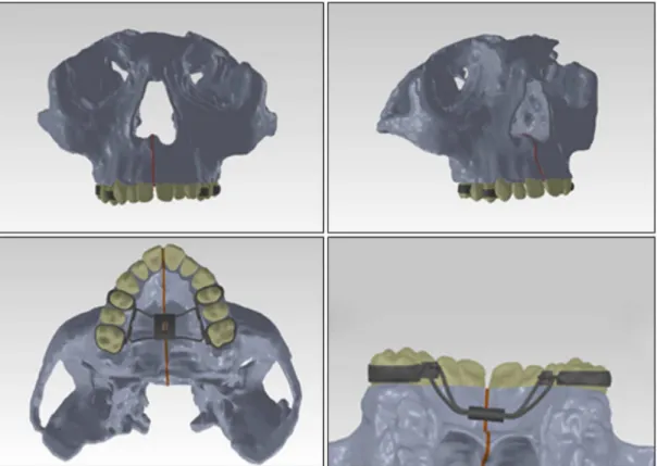
For computational simulations, a three-dimensional model (Figure 2) consisting of the maxillary bones and the bones closely related to them was developed. The model was based on Cone Beam Computed Tomography (CT) images of a 12 years old patient and this study has been approved by the Research
Ethics Committee of UFMG, Brazil (nº 171.147). The images generated by the CT in DICOM format
were imported into the computer aided design
software (CAD), Simpleware. For three-dimensional
reconstruction, 218 cross sections, 285 sagittal and
231 coronal sections were used, with 0.45 mm spacing
between them. Segmentation was done according to the tissues contrast, initially divided into bone, tooth and dental pulp elements. The bone was not separated between trabecular and cortical bone. After processing
these sections, the generated 3D model was exported
in STL format to Rapidform XOR3, software used for solid faces parameterization. The model was then exported in IGES format for SolidWorks 12, another
CAD software, to reine the geometry. Considering the
model symmetric, it was half-sectioned to reduce the complexity and the number of nodes of the FE model.
The structures that compose the model were considered as isotropic linear elastic, given the limitations in representing the bone biomechanical behavior, and as an initial study of the skull stresses. The real mechanical behavior of the tissues is time dependent, and this characteristic should be further studied to develop a more realistic material model where stress relaxation effects can be considered. The considered mechanical properties, Young’s modulus (E) and Poisson’s ratio, were as follows:
Bone, 10000 MPa and 0.3 (Serpe et al., 2014); Teeth,
20000 MPa and 0.3 (Tanne et al., 1989); Periodontal Ligament, 0.69 MPa and 0.49 (Yoshida et al., 2001);
Expander/Steel 200000 MPa and 0.33 (Hibbeler, 2002), respectively. The Young’s modulus assigned to the bone (10000 MPa) was estimated in terms of the
proportion of cortical bone (13700 MPa) and trabecular bone (1370 MPa) present in the cranium (Serpe et al., 2014), since the model used was composed of a single
Figure 2. Complete 3D model with palatal expander ixed to posterior teeth (in light gray: bone; dark gray: palatal expander/steel; beige:
type of bone tissue aiming to reduce the number of mesh nodes. The consideration of the bone as a homogeneous material is based on an homogenization with the purpose to reduce the computational cost of the analysis, considering that the main focus of the model was to examine the effect of different assumptions for the MPS. For each analysis, the functional unit representing the suture was considered with different
mechanical behaviors to evaluate how it inluences
the results of the simulations. Model (i) represented the maxilla without MPS (MPS unit was removed) while for the remaining models the MPS had different constitutive properties. In models (ii) and (iii), MPS was considered linear elastic, with E equal to 1 MPa and 0.01 MPa, respectively, and Poisson’s ratio of 0.49. In addition to these hypotheses, the suture unit was considered to have a bilinear elastic behavior for Model (iv), (E initial = 1 MPa, threshold stress
(transition) at 0.1 MPa and E inal = 0.01 MPa).
The bilinear model was used to provide a more realistic representation. This model represents the difference in suture stiffness before and after its breakup/separation. The initial elastic modulus (1 MPa) represented the organized connective tissue behavior, which is its main suture component (Provatidis et al., 2007). After its partial failure, the MPS has lower expansion restriction. Preliminary FE analyses were done switching the threshold stress value between 0.5, 0.1 and 0.05 MPa. Based on preliminary FE displacement results and analyzing the parameters to adjust the bilinear model simulations to clinical results (Ballanti et al., 2010; Weissheimer et al., 2011), a stress value of 0.1 MPa was assigned as the threshold for changing the elastic modulus. This represents the stress level at which the disorganization of the MPS functional unit occurs. After reaching this limiting value,
the elastic modulus is reduced (E inal = 0.01 MPa) to
represent an unorganized connective tissue. All these assumptions were made to represent the MPS opening as observed in clinical studies found in the literature (Ballanti et al., 2010; Weissheimer et al., 2011).
The mesh was generated using ANSYS 14.5 and resulted in a model with 462,916 tetrahedral elements
and 749,935 nodes. The boundary conditions were
applied in the same region where the symmetry was used to restrict lateral movement (Figure 3). In the posterior region of temporal bone, total or partial movement restrictions were applied, to represent the constraints imposed by the skull base. This assumption was done considering that skull bones have displacements limited by the anterior cranial base structures. As in the present work the model is not represented by the full skull, some areas were restrained based in the displacement results obtained by clinical studies (Ballanti et al., 2010; Weissheimer et al., 2011). A partial displacement restriction (yellow areas in
Figure 3, marked as “B”, “C” and “E”) was applied to only Y-axis. All the constraints were imposed
only in the posterior region of the model (“D” area
in Figure 3), as far as possible from the face, in order
not to inluence the stress distribution/results in the
anterior region of the skull (face).
The medial face of the expander unit was chosen to apply the displacement on the horizontal axis (X axis), as performed by the expander screw (“A” area in Figure 3), and also to restrict the displacement in the vertical and anteroposterior axes, as required by the whole appliance structure. The offsets applied in the simulations were 0.125 mm to one side (overall
0.25 mm – an activation of the unit) and 3.75 mm,
simulating the average total displacement in RME
(overall 7.5 mm – 30 activations).
The simulations were performed on the left half of the model considering its symmetry and the results mirrored for visualization.
Results
For all results of tensile and compressive stresses occurring at the bone, the detected maximum (peak) values, shown in the color charts on the following
igures, are located in regions where the boundary
conditions were applied (posterior region of the model, Figure 3). As it is not a region of interest for this study, these points were not indicated on the following images.
To evaluate the inluence of MPS on stress
distribution in the initial stages of RME, models (i) and (ii) were simulated with only one palatal
expander activation (0.125 mm). As these irst models
considered the assumption of linear elastic behavior for the MPS, common in the literature (Romanyk et al.,
2013), which is a great simpliication considering the
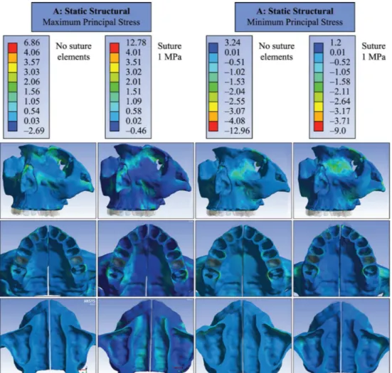
relaxation present in connective tissues, this analysis aimed to reduce the simulation error, especially for large applied displacements. The results showed that, when MPS was removed from the model (i), the peak of maximum principal stresses was in the range of 1 MPa, close to the orbit and the lingual surface of
the alveolar bone, near the irst molar (Figure 4). When MPS was considered (Model (ii)), a region of maximum stresses in alveolar bone was observed at buccal and lingual sides close to the teeth used as support, at the beginning of the zygomatic process
of the maxilla, nasal loor and internal walls of the
nasal cavity, resulting in peaks from 1.5 to 2 MPa. Regarding minimum principal stresses, there was also difference between models with and without MPS. With the presence of the suture, stress peaks were located in the medial wall of the orbit increased, ranging from 1.5 to 2 MPa (Figure 4).
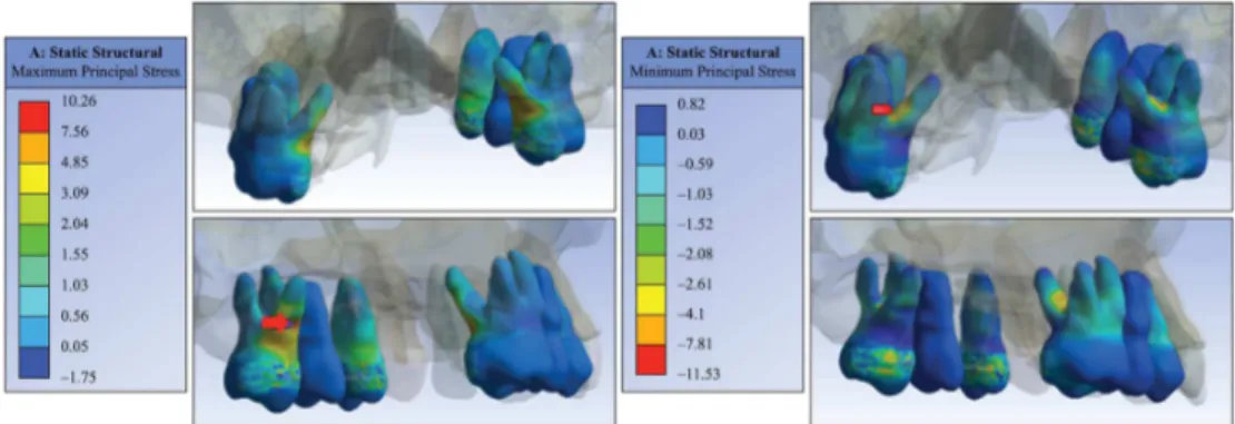
Dental elements used as support were also evaluated
mechanically. For a single screw activation of the tooth-supported expander, results showed tensile stress
peak of 10 MPa in the middle third of the irst molar
palatal root and –11 MPa compressive stress peak
near the fulcrum region between the irst molar roots
(Figure 5). The reaction force found when applied one activation on expansor’ medial surface was 25 N.
To assess the stresses generated by the entire
displacement applied by the expander (3.75 mm on each side, overall 30 activations), when the MPS has
a lower expansion restriction after its partial failure, a bilinear elastic model was adopted (Model (iv)).
The results showed that the maximum principal stress is distributed throughout the orbit (in the anterior and inferior border), canine fossa of malar surface, buccal
face of alveolar bone (close to irst molar and irst
premolar), palatal side of the alveolar bone, lateral wall of the nasal cavity, nasal bone and extended along the superior medial orbital wall with peaks
of 50.5 MPa. The nasal loor experienced tensile
stresses along its length with peaks up to 22.5 MPa. For minimum principal stress, also shown in Figure 6,
Figure 5. Maximum and minimum principal stresses distribution in the dental elements when applied one activation on tooth-supported expander (Model (ii)).
peaks up to –56.5 MPa were observed in the lower region of the medial orbital wall. In the canine fossa region of the maxillary bone and extending to the zygomatic arch, peak stresses reached –26 MPa.
At the nasal loor and the palatal area, results showed
compressive stresses in median regions with values between –8.5 and –11 MPa.
When the bilinear behavior for MPS was considered,
there was a signiicant increase in processing time.
An Intel (R) X5670 computer, with 2 GHz processor and RAM of 24 GB required approximately 144 hours to complete the simulation, a high operational cost when compared to the linear model, which required an average of 5 minutes of processing time.
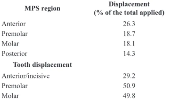
The expander showed a large dental effect due to RME. This can be observed in Table 1, which compares the displacement predicted in MPS (desirable skeletal effect of RME) with the one predicted for the tooth occlusal surface. The ratio between the MPS opening
and displacement of dental crown is close to 1:3, at
premolar and molar regions.
Models (i) and (iii), without and with (E = 0.01MPa) MPS elements respectively, were also simulated when subjected to the total displacement. The simulation resulted in displacement between bone ends of MPS and it was compared to the bilinear model in Table 2.
The higher rigidity of the suture, in the initial region of the bilinear model, reduces the total amount of the suture opening, when compared to cases where only the elastic modulus suggesting disorganized tissue was considered (E = 0.01 MPa). This was also
the case when comparing the results with the ones obtained from the model without MPS elements. It was observed that the presence and stiffness of the sutures
quantitatively inluence the removal of the MPS bone
ends, as well as the considered mechanical behavior.
Discussion
The inluence of MPS in the FE model was
assessed by comparing the stress distribution results, in the presence or absence of MPS elements and also in relation to the mechanical behavior assigned to it. The results obtained from this computational study show that an adequate MPS constitutive model is necessary to analyze RME by FEM, which is in accordance with
other studies that suggested a signiicant inluence of
MPS on the stresses and strains of adjacent structures (Provatidis et al., 2008; Romanyk et al., 2013).
When the MPS elements were suppressed – simulating surgically sectioned suture –, the stress values were considerably lower (Figure 4). But only when the goal is to simulate the RME assisted surgically, a model without the MPS elements can realistically represent the clinical situation. For the remaining situations it would be required, ideally, carrying out mechanical tests for the determination of a reliable constitutive model. However, in the absence of this ideal constitutive model that should consider the viscoelastoplastic behavior for MPS and damage, a bilinear behavior was proposed in this study.
The bilinear behavior is represented in a constitutive model that has a threshold stress value after which the elastic modulus changes. In this case, when this value is achieved, the elastic modulus for the MPS decreases radically, representing the stress level on MPS before partial rupture. The threshold stress value
was estimated by a itting obtained after repeated
FE simulations. For this preliminary tests, it was assigned between 0.5, 0.1 and 0.05 MPa to threshold and the value of 0.1 MPa was chosen as it led to the predicted displacements results for the MPS bone ends (Table 2) found in clinical studies (Ballanti et al., 2010; Weissheimer et al., 2011).
According to some clinical studies, the suture opening depends on the skeletal maturation and usually occurs in a “V” shape, with the fulcrum in the posterior region (Bishara and Staley, 1987; Weissheimer et al., 2011). The displacements variations found in clinical
studies were in the range of 32% to 45% in the palatal anterior region and 12 to 32% in the palatal posterior
region (Ballanti et al., 2010; Weissheimer et al., 2011) and this displacement was used as a parameter to validate the computational models.
Table 1. Displacement results predicted for midpalatal suture (MPS)
and dental crown areas with bilinear model for MPS.
MPS region Displacement
(% of the total applied)
Anterior 26.3 Premolar 18.7 Molar 18.1 Posterior 14.3 Tooth displacement Anterior/incisive 29.2 Premolar 50.9 Molar 49.8
Table 2. Predicted displacement results to midpalatal suture (MPS) for different mechanical behavior (% of the total displacement applied by the expander).
MPS region Bilinear MPS 0.01 MPa MPS MPS absent
Anterior 26.3 40.8 45.3
Premolar 18.7 28.4 31.5
Molar 18.1 26.1 27.1
The removal of the suture, related to the total displacement applied, varied according to the behavior assumed for MPS (bilinear, linear and absent). The large variation in the displacements observed when changing tissue behavior from linear to bilinear agrees with the statement that different mechanical behaviors of the suture are related to the differences in clinical RME outcomes, as suggested by Lee et al. (2009). This assumption could be extrapolated to
clinical results and propose that different ossiication
stages and imbrications levels of the MPS, that affects the stiffness of the suture, may partly explain the variability of the measures for palatal opening in clinical RME studies.
All models in the present study predicted the “V” shaped opening of MPS (Table 2) but the bilinear model showed smaller displacement than the other cases, probably because this model considers the change in stiffness that occurs in MPS after its rupture. The difference observed on results enlightens the
effect of the simpliication considered when linear
elastic properties were applied for MPS. This fact was sustained also by the stress predicted for the FE models, as biomechanical studies (Gautam et al., 2007;
Jafari et al., 2003) that point out to high stresses in various skull bones.
The peak of von Mises stresses up to 321 MPa
were observed for nasal bone, nasomaxillary suture, nasofrontal suture, anterior border of frontal process of the zygomatic bone (Jafari et al., 2003). Gautam et al. (2007) obtained von Mises stresses up to 459 MPa in frontomaxillary, nasomaxillary, and frontonasal sutures. However, these results do not represent quantitative
reliability due to model simpliications, such as
the use of shell element discrete model requiring a
simpliied geometry (Jafari et al., 2003) and absence of periodontal ligament and linear elastic properties for sutures and bone. As previously mentioned, the bone partially relaxes between expander activations, which
makes it dificult to compare the values generated by
the sum of displacements directly applied in a model with linear elastic material behavior.
Despite of displacements, the bilinear model
showed considerable lower stress peaks on skull bone. To simulate the complete expansion promoted by RME, the bilinear model could generates more acceptable results for predicted MPS removal bone ends and the maximum principal stresses predicted was close to 50 MPa distributed throughout the orbit, canine fossa, alveolar bone (close to, nasal cavity and nasal bone (Figure 5). This model also kept a distribution pattern similar to other studies in the literature (Jafari et al., 2003; Provatidis et al., 2008), reasserting that forces applied by the expander devices are not only restricted to the intermaxillary suture.
The maxillary complex behavior during RME was describe by Isaacson and Ingram (1964) when a gauge was adapt in the palatal expander and showed that forces produced by the expander are not cumulative, it
reduced signiicantly between activations and remain
throughout treatment within the range of 9 N and 45 N (Figure 1). This result suggests that the maxillofacial complex absorbs the displacement imposed by palatal expander between activations and the linear model could not be a good option for FEM. Aiming to obtain stress values consistent with the limitations of the linear
model, only the efforts of irst expander activation
was predicted when this constitutive behavior have been applied (Model (ii)). However the linear model showed a distribution pattern of maximum stresses similar to other studies in the literature (Jafari et al.,
2003; Provatidis et al., 2008), such as nasal bone, zygomatic arch and nasomaxillary suture, but did not exceed 6 MPa for these regions (Figure 4) when only one activation was applied. This value could be more reliable considering the non-accumulative stress by MPS.
Assuming the force range assessed on palatal expander (Isaacson and Ingram, 1964) and as one more FEM validation, the reaction force of bilinear model (Model (iv)) was requested. The value predicted on the expander appliance for one activation was 25 N, it belongs to clinical range of force evaluated in the palatal expander. Finally, a good representation of the cases studied was obtained, even though the used model did not contain a complete representation of the skull.
Considering the limitation from FE analysis, the
obtained results proved that the simpliication of
complex behavior of some materials has an important
inluence on stress analysis. In addition, some inal
remarks can be made:
1. The presence and stiffness of the sutures inluence
the displacement between the MPS bone ends and the stress provided computationally in maxillary structures;
2. The high level of stresses promoted over deeper craniofacial skeleton structures demonstrates that expander devices effects are not only restricted to the intermaxillary suture, but also distributed in other sutures of the nasomaxillary complex, and showed the role of the entire circummaxillary complex in the RME;
3. For this FEM, the elastic bilinear behavior
Considering the predicted results for MPS with bilinear properties were more consisted than linear model and it has less computational time than viscoelastic model, the bilinear model should be a good option to represent the MPS on FEM for rapid maxillary expansion.
Acknowledgements
The authors acknowledge the support of the Brazilian research funding agencies CAPES and FAPEMIG and also the Renato Archer Information Technology Center (CTI) in Campinas, Brazil, for assisting in the model generation.
References
Ballanti F, Lione R, Baccetti T, Franchi L, Cozza P. Treatment and post treatment skeletal effects of rapid maxillary expansion investigated with low-dose computed tomography in growing subjects. American Journal of Orthodontics and Dentofacial Orthopedics. 2010; 138(3):311-7. http:// dx.doi.org/10.1016/j.ajodo.2008.10.022. PMid:20816300.
Bishara SE, Staley RN. Maxillary expansion: clinical implications. American Journal of Orthodontics and Dentofacial Orthopedics. 1987; 91(1):3-14. http://dx.doi. org/10.1016/0889-5406(87)90202-2. PMid:3541577.
Gautam P, Valiathan A, Adhikari R. Stress and displacement patterns in the craniofacial skeleton with rapid maxillary expansion: a finite element method study. American Journal of Orthodontics and Dentofacial Orthopedics. 2007; 132(1): 5.e1-11. http://dx.doi.org/10.1016/j.ajodo.2006.09.044. PMid:17628242.
Hibbeler RC. Mechanics of Materials. 5th ed. New Jersey: Prentice Hall; 2002.
Holberg C, Rudzki-Janson I. Stresses at the cranial base induced by rapid maxillary expansion. The Angle Orthodontist. 2006; 76(4):543-50. PMid:16808557.
Isaacson RJ, Ingram AH. Forces produced by rapid maxillary expansion. II. Forces present during treatment. The Angle Orthodontist. 1964; 34:261-70.
Iseri H, Tekkaya AE, Öztan Ö, Bilgiç S. Biomechanical effects of rapid maxillary expansion on the craniofacial skeleton, studied by the finite element method. European Journal of Orthodontics. 1998; 20(4):347-56. http://dx.doi. org/10.1093/ejo/20.4.347. PMid:9753816.
Jafari A, Shetty KS, Kumar M. Study of stress distribution and displacement of various craniofacial structures following application of transverse orthopedic forces: a three-dimensional FEM study. The Angle Orthodontist. 2003; 73(1):12-20. PMid:12607850.
Lee H, Ting K, Nelson M, Sun N, Sung S. Maxillary expansion in customized finite element method models. American Journal of Orthodontics and Dentofacial Orthopedics. 2009; 136(3):367-74. http://dx.doi.org/10.1016/j.ajodo.2008.08.023. PMid:19732671.
Provatidis C, Georgiopoulos B, Kotinas A, Mcdonald JP. On the FEM modeling of craniofacial changes during rapid maxillary expansion. Medical Engineering & Physics. 2007; 29(5):566-79. http://dx.doi.org/10.1016/j. medengphy.2006.03.007. PMid:17241809.
Provatidis CG, Georgiopoulos B, Kotinas A, Mcdonald JP. Evaluation of craniofacial effects during rapid maxillary expansion through combined in vivo/in vitro and finite element studies. European Journal of Orthodontics. 2008; 30(5):437-48. http://dx.doi.org/10.1093/ejo/cjn046. PMid:18927087. Romanyk DL, Collins CR, Lagravère MO, Toogood RW, Major PW, Carey JP. Role of the midpalatal suture in FEA simulations of maxillary expansion treatment for adolescents: a review. International Orthodontics. 2013; 11(2):119-38. PMid:23537640.
Serpe LCT, Torres LAG, Freitas-Pinto RU, Toyofuku ACMM, Las Casas EB. Maxillary biomechanical study during rapid expansion treatment with simplified model. Journal of Medical Imaging and Health Informatics. 2014; 4(1):137-41. http://dx.doi.org/10.1166/jmihi.2014.1233. Tanne K, Hiraga J, Sakuda M. Effects of directions of maxillary protraction forces on biomechanical changes in craniofacial complex. European Journal of Orthodontics. 1989; 11(4):382-91. PMid:2591486.
Verrue V, Dermaut L, Verhegghe B. Three-dimensional inite element modelling of a dog skull for the simulation of initial orthopaedic displacements. European Journal of Orthodontics. 2001; 23(5):517-27. http://dx.doi.org/10.1093/ ejo/23.5.517. PMid:11668871.
Wang Q, Wood SA, Grosse IR, Ross CF, Zapata U, Byron CD, Wright BW, Strait DS. The role of the sutures in biomechanical dynamic simulation of a macaque cranial finite element model: implications for the evolution of craniofacial form. The Anatomical Record. 2012; 295(2):278-88. http:// dx.doi.org/10.1002/ar.21532. PMid:22190334.
Weissheimer A, Menezes LM, Mezomo M, Dias DM, Lima EMS, Rizzatto MD. Immediate effects of rapid maxillary expansion with Haas-type and hyrax-type expanders: a randomized clinical trial. American Journal of Orthodontics and Dentofacial Orthopedics. 2011; 140(3):366-76. http:// dx.doi.org/10.1016/j.ajodo.2010.07.025. PMid:21889081.
Yoshida N, Koga Y, Peng CL, Tanaka E, Kobayashi K. In vivo measurement of the elastic modulus of the human periodontal ligament. Medical Engineering & Physics. 2001; 23(8):567-72. http://dx.doi.org/10.1016/S1350-4533(01)00073-X. PMid:11719079.
Authors
Larissa Carvalho Trojan Serpe1*, Estevam Barbosa de Las Casas1, Ana Cláudia Moreira Melo Toyofuku1, Libardo
Andrés González-Torres1
1 Grupo de Engenharia Biomecânica, Escola de Engenharia, Universidade Federal de Minas Gerais – UFMG, Av. Antônio