(Recebido em 29/02/2012; Texto final em 01/03/2012). Artigo originalmente publicado no CONSOLDA 2011
which are particularly interesting due to the weight saving potential. The plunging of an especially designed non-consumable and rotating tool creates a connection between overlapped sheets through frictional heat and plastic deformation. Minimum material loss is observed, and therefore a fully consolidated joint with lat surface (no keyhole) is obtained. In the current study, the effect of FSpW parameters, such as rotational speed, plunge depth and dwell time, on lap shear strength of AZ31 magnesium alloy joints was investigated. The optimization of input process parameters was carried out through Taguchi approach of DOE. Analysis of variance was applied to determine the individual importance of each parameter. Main effect plots were used to indicate the best levels for maximizing lap shear strength. The results show that tool plunge depth has the higher effect on the weld strength, followed by rotational speed and dwell time.
Key-words: Friction spot welding; AZ31 magnesium alloy; Taguchi method.
Resumo: A soldagem por fricção por ponto (FSpW) é um processo de soldagem no estado sólido adequado para a produção de juntas pontuais, especialmente em materiais leves, que são particularmente interessantes devido ao potencial de redução de peso. A penetração de uma ferramenta não-consumível e rotacional especialmente desenvolvida cria uma junção entre as placas sobrepostas através de calor por fricção e deformação plástica. A perda de material é mínima, obtendo-se, portanto, uma junta totalmente consolidada com superfície plana (sem furo). Neste trabalho, investigou-se o efeito dos parâmetros do FSpW, tais como velocidade de rotação, profundidade de penetração e tempo de residência, na resistência ao cisalhamento das juntas de liga de magnésio AZ31. A otimização dos parâmetros de entrada do processo foi realizada através do método de Taguchi de DOE. A análise de variância foi aplicada para determinar a importância individual de cada parâmetro. Os gráicos dos efeitos principais foram utilizados para indicar os melhores níveis que maximizam a resistência ao cisalhamento. Os resultados mostram que a profundidade de penetração da ferramenta possui a maior inluência sobre a resistência da solda, seguida da velocidade de rotação e tempo de residência.
Palavras-chave:Soldagem por fricção por ponto; Liga de magnésio AZ31; Método de Taguchi.
1. Introduction
Friction spot welding (FSpW) is a spot solid state technology developed and patented by GKSS Forschungszentrum (now Helmholtz-Zentrum Geesthacht), Germany [1]. A three-part tool comprising pin, sleeve and clamping ring is used to join two or more similar/dissimilar sheets of lightweight materials
in lap coniguration, such as aluminum (Al) and magnesium
(Mg) alloys. The conception of the process aims to eliminate some disadvantages usually observed in other spot-like joining
technologies, such as weight penalty, dificulty of automation,
requirement for sealants and corrosion problems in mechanical fastening [2], and the presence of a keyhole after the process in friction stir spot welding (FSSW).
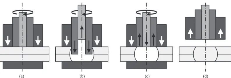
Depending on the plunging component, the process can be divided in two variants with four steps: pin plunge and sleeve
plunge [2]. Clamping ring initially ixes the sheets against
a backing plate while pin and sleeve begin to rotate in the same direction on the upper surface (Figure 1a). Rotating pin and sleeve are moved in opposite direction to each other (one is plunged into the material while the other moves upwards), creating a cavity where the plasticized material through frictional heat is accommodated (Figure 1b). After reaching the pre-set plunge depth, pin and sleeve retract back to the surface
of the plate forcing the displaced material to completely reill the
keyhole (Figure 1c). Finally, tool rotation is stopped and tool is
withdrawn from the joint leaving a lat surface with minimum
(a) (b) (c) (d) Figure 1. Illustration of sleeve plunge steps: (a) clamping and tool rotation, (b) sleeve plunge and pin retraction, (c) tool back to
surface level and (d) tool removal.
The mechanical performance of a FSpW connection is mainly dependent on the process parameters such as rotational speed (RS), plunge depth (PD) and dwell time (DT). Taguchi
technique of Design of Experiments (DOE) has been widely
applied to optimize the quality and reliability of materials manufacturing through the optimization of the input process
parameters without increasing the experiment time and cost [3].
With a special design of orthogonal arrays, Taguchi provides the optimum settings of parameters, which are insensitive to the variation in environmental condition and other noise effects
[4]. Three categories of quality characteristics are deined
in the analysis of Signal/Noise (S/N) ratio: lower-the-better, larger-the-better and nominal-the-best. The S/N ratio for each process parameter is calculated based on S/N analysis function. A larger S/N ratio is normally consistent with better quality characteristics regardless of the category. The level of larger S/N ratio is the optimal process parameter one. Analysis of variance
(ANOVA) is performed to investigate which parameters have a signiicant effect on the quality characteristic [5,6].
Several successful applications of Taguchi method have been reported in the optimization of solid state welding parameters.
Lakshminarayanan et al. [6] revealed that tool RS has the major
effect on the tensile strength (TS) of RDE-40 Al alloy friction stir
welds, followed by welding speed and axial force. An optimum TS of 303 MPa was predicted. Working with FSW on A319 Al
alloy, Jayaraman et al. [7] also presented the RS as the dominant parameter, and TS of the optimum combination of parameters was found to be 147 MPa. In both studies, the predicted values
of TS were in a reasonable agreement with experiment values.
Regarding friction based spot welding technologies, few research works using Taguchi method can be found in the literature. Hunt et al. [8] studied the effect of Swing-FSW (alternative
spot welding based on FSW) parameters on A6022-T4 Al alloy
and showed that hold time increases lap shear strength (LSS).
Taguchi approach was also used by Bilici et al. [9] to examine
the effect of FSSW parameters on high density polyethylene. DT was found to have the major effect on LSS, followed by tool RS and PD. The predicted value of LSS at the optimum levels was
similar to the experimental one.
In this study, Taguchi method is applied to investigate the
inluence of each FSpW parameter on LSS of AZ31 Mg alloy
joints and evaluate the combination of parameters that leads to the highest weld strength.
2. Materials and Methods
AZ31B-H24 Mg alloy sheets of 2 mm of thickness were
used in this investigation. FSpW sleeve plunge variant was used
to produce the welded specimens in lap-shear coniguration with 46 mm overlap according to ISO 14273:2000 standard. The tool system consisted of a clamping ring, 9 mm diameter sleeve and 6 mm diameter pin. Three main process parameters have been
varied in this study: rotational speed (RS), plunge depth (PD) and dwell time (DT). DT refers to the time in which sleeve and pin rotate without vertical displacement to allow better material
mixing. Weld strength has been characterized using lap shear
testing on a screw-driven Zwick testing machine with a constant cross head speed of 2 mm/min and at room temperature.
Several preliminary experiments were initially performed to ind out feasible working limits of the FSpW parameters. The
working range was decided upon by inspecting macrostructure and LSS. As shown in Table 1, each parameter was set up at three levels. Taguchi method was applied using Minitab
software for designing the experiment. Since each three-level
parameter has two degrees of freedom (DF = number of levels
– 1), the total DF required is six. The DF of selected orthogonal
array must be greater than or at least equal to the total DF, and
hence an L9 array (DF = 8) is suitable for the present study. LSS
comprehends the quality characteristic.
Table 1. Welding parameters and their levels. Parameter Symbol Level 1 Level 2 Level 3 Rotational speed
(rpm) RS 2000 2500 3000
Plunge depth
(mm) PD 2.3 2.7 3.0
8 3000 2.3 1.5 4.07 4.24 4.15 4.15 12.3643
9 3000 2.7 3 4.28 4.28 4.57 4.38 12.8105
Table 3. Main effects of LSS (mean and S/N ratio).
Level Mean LSS (kN) S/N ratio (dB)
RS PD DT RS PD DT
1 4.026 3.789 4.161 11.970 11.490 12.220
2 4.453 4.458 4.374 12.950 12.970 12.810
3 4.422 4.654 4.366 12.890 13.350 12.780
Delta 0.428 0.866 0.213 0.980 1.860 0.590
Rank 2 1 3 2 1 3
Table 4. ANOVA results for mean of LSS.
Source Mean LSS
DF SS MS F P%
RS 2 0.3413 0.1707 1.03 17.11
PD 2 1.2353 0.6176 3.74 61.93
DT 2 0.0874 0.0437 0.26 4.38
Error 2 0.3307 0.1653 - 16.58
Total 8 1.9947 - - 100.00
DF = degrees of freedom, SS = sum of squares, MS = mean square, F = F-test and P% = percentage of contribution.
Table 5. ANOVA results for S/N ratio of LSS.
Source S/N ratio
DF SS MS F P%
RS 2 1.8255 0.9127 1.01 18.10
PD 2 5.7961 2.8980 3.22 57.48
DT 2 0.6601 0.3300 0.37 6.55
Error 2 1.8014 0.9007 - 17.87
Total 8 10.0830 - - 100.00
3. Results and Discussion
LSS experimental values are presented in Table 2 along
with the calculated mean (average) and S/N ratio for each combination of parameters. S/N ratio is used in Taguchi method to measure the deviation of the quality characteristics from the
desired value. Since it is desired to maximize the response, the
S/N ratio was chosen according to the category of
“larger-the-better”. Table 3 gives mean LSS and S/N ratio calculated for
each parameter at all three levels. The mean response states the average value of the performance characteristic for each parameter at different levels. The mean of one level is calculated as the average of all responses obtained in that particular level.
The values updated in the last two rows of Table 3 are delta
value and rank, which help assessing which parameter has the greatest effect on the response. By taking the difference between the highest and the lowest average for a parameter, delta measures the size of the effect. Considering the calculated delta values, rank orders the parameters from the greatest to the least
effect on the response with numbers from 1 to 3 respectively.
The greatest variation of both mean and S/N ratio was observed for PD, revealing that this parameter has the most important effect on LSS. RS has a lower relevant effect and DT shows the lowest effect of all parameters.
ANOVA was carried out to establish the relative importance
of parameters in terms of variance and percentage of contribution
(P%) on LSS. Tables 4 and 5 show the ANOVA results of mean
and S/N ratio, respectively. F-test is based on comparing model and residual variances through the ratio between the model mean square and the residual or error mean square. F-value is
close to one when the variance values are similar, which means a low effect of the parameter on the response, whereas high
F-value indicates a signiicant effect [5]. P% is a function of sum
of squares and indicates the relative power of each parameter to
reduce the total variation [6,7]. Figure 2 shows the contribution
of the parameters.
In summary, LSS is signiicantly affected by PD, followed
by RS with a lower effect, both in terms of mean and S/N ratio. It suggests that PD is a key parameter to control LSS, which is in agreement with the achievements from main effects (Table
3). In the case of DT, the F-value below unity indicates that this
parameter does not take great effect on LSS, as evidenced by the low contribution on LSS.
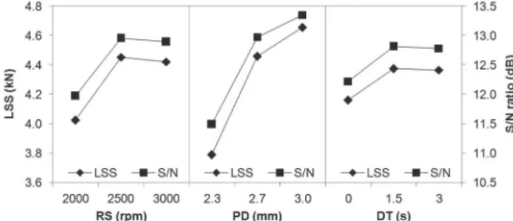
Figure 3 presents the main effects plots for mean LSS and S/N ratio. The latness proile of DT curve also indicates
the reduced contribution of this parameter on LSS, while the
importance of PD is once more conirmed by the steep proile
of its curve. In the investigated range, PD plot suggests an increase in this parameter to obtain better joints, while RS and DT plots indicate a slight reduction in the weld quality above the intermediate levels. As reported for FSSW process [10], it is possible that the heat input has a strong and direct correlation with mechanical performance of the weld. Clearly more heat is generated by friction when the parameters are individually
increased. When the heat eficiency is high, the reduction in the
viscosity of plasticized material leads to a decrease in torque and hence in the heat input.
Since larger S/N values correspond to better quality
characteristic with minimum variance, the purpose of DOE is to determine not only the maximum mean LSS but also the highest possible S/N ratio. Along with Table 3, Figure 3 states
that the highest value of LSS is achieved at the high level of PD and the medium levels of both RS and DT. Hence, Taguchi method suggests that the best settings to optimize LSS comprise
RS of 2500 rpm, PD of 3.0 mm and DT of 1.5 seconds. Note
that this combination of parameters is already included in the
L9 orthogonal array (condition 5 in Table 2). Since orthogonal
arrays do not test all possible combinations of parameters, interaction effect was not included in the optimization process.
A careful analysis of Table 2 indicates other combinations of parameters that provide LSS values as high as the value provided
by condition 5, such as conditions 3, 4 and 7. Figure 4 presents
the standard deviation for all combinations of parameters, which
varies from 0.02 (for condition 2) to 0.19 (for condition 7).
There are no substantial differences in the LSS results of the four conditions previously mentioned, suggesting similar heat input in such cases.
Figure 4. Mean and standard deviation plots for LSS.
Although there is not a standard way of obtaining the stress of the spot joint from the load, the lap shear stress (LSSt) is
deined as the ratio between LSS and the circular area of the
joint (considering the outer diameter of the tool component). This type of procedure is commonly adopted in cases where the real welding area is not measurable. In this study, LSS
varies from about 3.1 to 4.7 kN, which results in a variation of LSSt between 48.9 and 74.5 MPa. The LSSt value obtained
by rotational speed and dwell time. The determination of the optimum condition of parameters was not clear. The optimum
combination suggested by Taguchi method was found to be 2500 rpm of rotational speed, 3.0 mm of plunge depth and 1.5 seconds
of dwell time. However, standard deviation values indicated that other conditions of parameters provided similar strength. In the investigated range, friction spot welding technology showed a great potential over friction stir spot welding.
5. Acknowledgments
The authors would like to acknowledge the inancial support provided by CNPq (National Council for Scientiic and
Technological Development) and FAPESP (Sao Paulo Research Foundation), Brazil. Authors are also grateful to Dr. Sergio
Amancio for his assistance in the statistical ield.
6. References
[1] SCHILLING, C.; DOS SANTOS, J. Method and Device
for Linking at Least Two Adjoining Work Pieces by Friction
Welding. US Patent No. 6,722,556 B2. April 20, 2004
[2] DA SILVA, A.M. et al. Friction Spot and Friction Stir Spot
Welding Processes – A Literature Review. Bulletin of National
R&D Institute for Welding and Material Testing, v. 3, p. 36-44,
2007.
[3] MONTGOMERY, D.C. Design and Analysis of Experiments.
4th Edition. NY: John-Wiley & Sons, Inc, 2006.
[4] ROSS, P.J. Taguchi Techniques for Quality Engineering. NY: Tata McGraw Hill, 1988.
[5] XIANSHENG, N. et al. The use of Taguchi method to optimize the laser welding of sealing neuro-stimulator. Optics and Lasers in Engineering, v. 48, n. 3, p. 297-304, 2011. [6] LAKSHMINARAYANAN, A.K.; BALASUBRAMANIAN, V. Process parameters optimization for friction stir welding of
RDE-40 aluminum alloy using Taguchi technique. Transactions
of Nonferrous Metals Society of China, v. 18, n. 3, p. 548-554,
2008.
[7] JAYARAMAN, M. et al. Optimization of process parameters for friction stir welding of cast aluminum alloy A319 by Taguchi method. Journal of Scientiic & Industrial Research, v. 68, n. 1, p. 36-43, 2009.
Alloy 6022-T4. SAE International, 2006-01-0970, 2006. [9] BILICI, M.K.; YÜKLER, A.İ.; KURTULMUŞ, M. The Optimization of welding parameters for friction stir spot welding of high density polyethylene sheets. Materials and Design, v. 32, n. 7, p. 4074-4079, 2011.
[10] SU, P. et al. Energy Generation and Stir Zone Dimensions
in Friction Stir Spot Welds. SAE International, 2006-01-0971, 2006.
[11] YANG, Q. et al. Microstructure and Mechanical Properties of Friction Stir Spot Welded AZ31 Mg Alloy. In: 7th International