Peter KAŠŠAY1, Jaroslav HOMIŠIN2, Pavol ČOPAN3, Matej URBANSKÝ4
VERIFICATION OF TORSIONAL OSCILLATING MECHANICAL
SYSTEM DYNAMIC CALCULATION RESULTS
Summary. On our department we deal with optimization and tuning of torsional oscillating mechanical systems. When solving these problems we often use results of dynamic calculation. The goal of this article is to compare values obtained by computation and experimentally. For this purpose, a mechanical system built in our laboratory was used. At first, classical HARDY type flexible coupling has been applied into the system, then we used a pneumatic flexible shaft coupling developed by us. The main difference of these couplings over conventional flexible couplings is that they can change their dynamic properties during operation, by changing the pressure of the gaseous medium in their flexible elements.
Keywords: torsional vibration, Measurement, Dynamic Calculation.
WERYFIKACJA WYNIKÓW OBLICZE DYNAMICZNYCH
W WYKONANYM UK
Ł
ADZIE MECHANICZNYM DRGAJ CYM
SKR TNIE
Streszczenie. W naszej pracowni zajmujemy si optymalizacj i strojeniem układów mechanicznych drgaj cych skr tnie. W trakcie rozwi zywania tych problemów cz sto korzystamy z wyników oblicze dynamicznych. Celem niniejszego artykułu jest porównanie warto ci uzyskanych na podstawie oblicze z uzyskanymi w trakcie do wiadcze . Wykorzystali my do tego układ mechaniczny skonstruowany w naszym laboratorium, przy czym w jednym przypadku zostało w układzie zastosowane klasyczne elastyczne sprz gło typu HARDY, a w drugim wynalezione przez nas elastyczne sprz gło pneumatyczne ł cz ce wały. Najważniejsz cech różni c te sprz gła od klasycznych sprz gieł elastycznych jest to, że możliwe jest zmienianie ich wła ciwo ci dynamicznych bezpo rednio podczas pracy za pomoc zmiany ci nienia medium gazowego w elementach elastycznych.
Słowa kluczowe: drganie skr tne, pomiar, obliczenie dynamiczne.
1. INTRODUCTION
When designing torsional oscillating mechanical systems, it is usually necessary to rely on the results of dynamic calculation. There we try to find out especially the size of dynamic component of load torque during operation. This calculation should reflect the situation in the
Letná 9, 042 00 Košice, Slovak Republic, e-mail: [email protected], [email protected],
3
already built mechanical system as closely as possible. This requires to have the most accurate input values. In order to check the accuracy and reliability of dynamic calculation, we decided to use a mechanical system implemented in our laboratory. By identifying the input values of mechanical system individual elements, we relied on catalogue data of producers and on parameter values measured by us. We also investigated the effect of the torque sensor location on the resulting measured torque time course.
2.EXAMINED MECHANICAL SYSTEM
The dynamic calculation results verification we performed on a mechanical compressor drive system (Fig. 1). The system consists of three-phase asynchronous electric motor which drives three-cylinder air compressor. The time course of load torque is sensed by a torque sensor. Pneumatic supply of flexible shaft flexible coupling is handled by use of radial rotary air supply. Measurements were performed on the system with a HARDY type flexible shaft coupling and with tangential pneumatic flexible shaft couplings with fully interconnected pneumatic flexible elements type 4-2/70-T-C.
Fig. 1. Mechanical system of compressor drive Rys. 1. Układ nap du mechanicznego kompresora
Individual elements of examined mechanical system have the following parameters:
Parameters motor:
Three-phase asynchronous squirrel-cage motor SIEMENS 1LE1002-1CB, rated power of the electric motor PM= 7,5 kW,
rated speed electric motor nM = 1450 ot/min, mass moment of inertia of the electric motor IE = I1* = 0,024 kg.m2. The speed of the electric motor can be continuously changed with frequency converter.
Parameters compressor:
Three-cylinder piston air compressor ORLIK 3JSK-75,
mass moment of inertia of the compressor IK=I5* =0,02967 kg.m2 mass moment of inertia of the flanges I4* =0,0151 kg.m2 atmospheric pressure pa = 100 kPa, overpressure at the inlet pps = 0 kPa, overpressure at the discharge ppv = 400 kPa
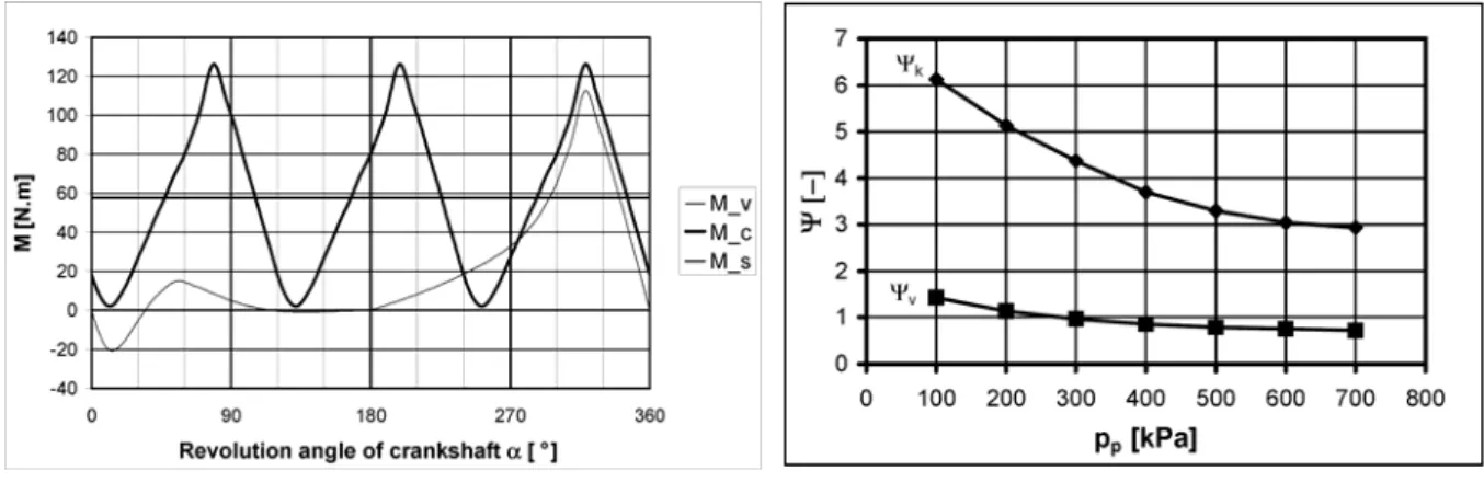
real (measured) values as recommended in [5]. Calculated course of compressor load torque at selected speed n = 1450 rpm is shown on Fig. 2.
Fig. 2.Load torque of the compressor at speed n = 1450 rpm
Rys. 2. Obci żaj cy moment skr tny kompresora przy obrotach n = 1450 obr/min-1
Fig. 3.Relative damping of pneumatic flexible shaft coupling
Rys. 3. Stopniowe tłumienie elastycznego sprz gła pneumatycznego ł cz cego wały
where: Mv torque of first cylinder, Mc torque of whole compressor, Ms static (mean) torque of compressor.
Parameters of HARDY flexible coupling:
Dynamic torsional stiffness kdyn 3,117Mstat 1280 N.m.rad-1, coefficient of relative damping
= 1. moment of inertia on motor side I2* = 0,00178 kg.m2, moment of inertia on compressor side I3* = 0,009319 kg.m2.
Parameters of of pneumatic flexible shaft coupling type 4-2/70-T-C:
Dynamic torsional stiffness kdyn 1,925pp 740,22 N.m.rad-1, moment of inertia on motor side I2* = 0,0672 kg.m2,
moment of inertia on compressor side I3* = 0,0757 kg.m2.
Mechanical properties measurements were performed with both of flexible shaft couplings. Dynamic properties were determined by the method of free oscillations [4]. This method gives good results for dynamic torsional stiffness. The values of relative damping coefficient however, are more influenced by the frequency and amplitude of twist angle. Therefore we used data from the manufacturer for HARDY coupling. For the pneumatic shaft couplings data from the work [8] are used for comparison. Where the author established damping parameters by kinematic excitation with frequency 22 rad.s-1. Courses of relative damping coefficient depending on the overpressure in the coupling pp by free oscillation
v and by kinematic excitation
k we can see on Fig. 3.3.DETERMINING THE COURSE OF LOAD TORQUE ON TORQUE SENSOR
Time course of load torque transmitted by flexible shaft couplings, we can determine by dynamic calculation of two-mass torsional oscillating mechanical system [3], [7]. Where for I1 we substitute 2*
* 1
1 I I
I , and for I2 we substitute 5* * 4 * 3
2 I I I
Since the torque sensor is placed between the compressor (torsional vibration exciter) and flexible coupling, so the measured time course will differ from the dynamic calculation results of the torque transmitted by flexible shaft couplings. Values that we should obtain by experimental measurements can be determined using the following procedure.
Let us have two masses (0) with mass moments of onertia IA and IB, which are rigidly connected by an intangible shaft representing the torque sensor. Torques MA and MB. are acting on them
Fig. 4. Action of torques on two rigidly connected masses
Rys. 4. Działanie momentów skr tnych na dwie sztywno ze sob poł czone masy
Torque M acting on intangible shaft will have a value:
B A
A B
B A
B A
I I
I M
I I
I M
M
(1)
Torque M will be affected by torque courses of both masses, as well as by the mass ratio IA/IB. When applied to our case the first mass will be represented by the halves of flexible coupling and the rotating parts of torque sensor, together with the connecting flanges (IA = I3*). The second mass consists of other half of the torque sensor rotating parts, compressor crank mechanism and connecting flanges (IB = I4*+ I5*).
4.COMPARISON OF THEORETICAL AND EXPERIMENTAL RESULTS FOR
MECHANICAL SYSTEM WITH HARDY FLEXIBLE COUPLING
In the mechanical system with HARDY flexible coupling the mass ratio is IA/IB = 0,21. So mass IA, on which acts dynamic load torque of flexible coupling MdS is significantly smaller than mass IB on which acts dynamic load torque of compressor MdK.
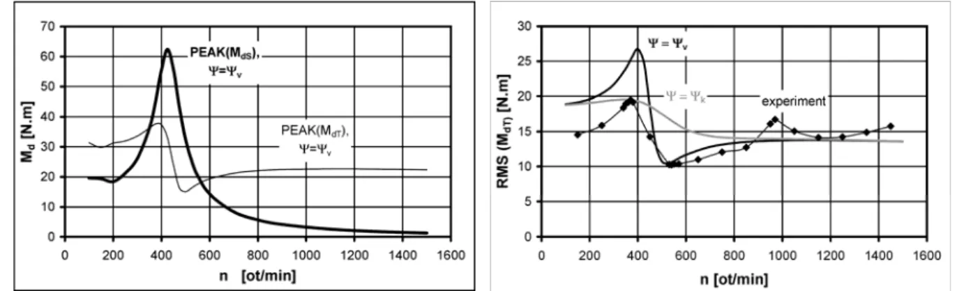
Fig. 5. Course of calculated dynamic torques Rys. 5. Przebieg obliczonych dynamicznych momentów skr tnych
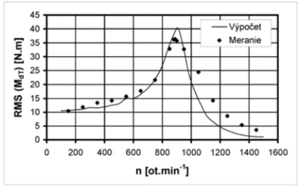
Fig. 6. Effective torque on sensor for HARDY flexible coupling
According to equation (1) the resulting time course on torque sensor MdT should be more close to time course of flexible coupling torque. This is shown on 0, where the course of peak torques on the coupling PEAK(MdS) and on the sensor PEAK(MdT) are similar. On the mechanical system measurements of effective torque RMS(MdT) were taken. Comparison of the values obtained by calculation and measurement we can see on 0.
5.COMPARISON OF THEORETICAL AND EXPERIMENTAL RESULTS FOR
MECHANICAL SYSTEM WITH PNEUMATIC FLEXIBLE COUPLING
In the mechanical system with pneumatic flexible coupling the mass ratio is IA/IB = 1,69. So mass IA, on which acts dynamic load torque of flexible coupling MdS is larger than mass IB on which acts dynamic load torque of compressor MdK. Acoording to equation (1) the final time course of torque MdT on the sensor will be significantly influenced by the dynamic component of compressor torque. We can see it also on the following course, where in speed area over the resonance the peak value of torque on sensor PEAK(MdT) increases (0). Pak values curses of dynamic torque on the coupling PEAK(MdS) and on the sensor PEAK(MdT) depending on operating speed n are shown on 0 for relative damping determined by free oscillation. Listed courses were calculated for pp = 100 kPa value of overpressure in the coupling. Comparison of experimental results with calculated values for coefficient of relative dampig determined by free oscillation
v and by kinematic excitation
k is on 0.Fig. 7. Course of calculated dynamic torques Rys. 7. Przebieg obliczonych dynamicznych
momentów skr tnych
Fig. 8. Effective value of torque on the sensor, at a overpressure pp = 100 kPa
Rys. 8. Warto ć efektywna momentu skr tnego na czujniku przy nadci nieniu pp = 100 kPa
6. CONCLUSION
We can say that the measured and calculated values for HARDY coupling reported a quite good agreement. Position of the speed at resonance against measurement varies approx. 2%, and the maximum value at the resonance approx. by 11%. Higher tolerances at higher speeds are probably caused by the fact that flexible coupling changes its damping properties by influence of amplitude and frequency of vibration.
In contrast, for the damping by kinematic excitation
k, the difference in speed at resonance is approx. 5%, but the maximum of effective value differs by only 0.5%. Thus, the size and position of resonance (local maximum) is very close to the measured values. In the future, it would be necessary to pay more attention to damping of pneumatic flexible shaft couplings. Significant impact on its value has the airflow in their interconnection tubes, which is influenced by the frequency and amplitude of the coupling twist angle.If we want to measure torque transmitted by flexible shaft coupling with torque sensor, it is best to place the torque sensor on the opposite side as torsional vibration exciter is located. Then only dynamic load torque transmitted by flexible shaft coupling will be reflected in measured data, In case that sensor is positioned between shaft coupling and exciter of torsional vibration, the mass moment of inertia on the side of flexible coupling should be as small as possible.
Acknowledgement
This paper was written in the framework of Grant Project VEGA: „1/0688/12 – Research and application of universal regulation system in order to master the source of mechanical systems excitation”.
Bibliogpraphy
1. Haľko J., Pavlenko S.: Analytical Suggestion of Stress Analysis on Fatigue in Contact of the Cycloidal Vascular Gearing System. Zeszyty Naukowe Politechniki l skiej, s. Transport, z. 76, Gliwice 2012, s. 63-66.
2. Handrik M., Vaško M., Kopas P.: Parallel and Distributed Implementation of Optimization Algorithms in FE Analyses. Zeszyty Naukowe Politechniki l skiej, s. Transport, z. 76, Gliwice 2012, s. 67-74.
3. Homišin J.: Nové typy pružných hriadeľových spojok, vývoj výskum – aplikácia. Vienala, Košice 2002.
4. Homišin J., Čopan P., Urbanský M.: Experimental determination of characteristic properties of selected types of flexible shaft couplings. Zeszyty Naukowe Politechniki
l skiej, s. Transport, z. 81, Gliwice 2013, s. 51-57. 5. Chlumský V.: Pístové kompresory. SNTL, Praha 1958.
6. Jakubovičová L., Sága M., Vaško M.: Contribution to discrete optimising of beam structures subjected to fatique damage. Transactions of the Universities of Košice, No. 2 (2011), p. 137-142.
7. Kaššay P.: Optimalizácia torzne kmitajúcich mechanických sústav metódou extremálnej regulácie: doktoranská dizertačná práca. TU v Košiciach, Košice 2008.
8. Krajňák J.: Vysokopružná pneumatická hriadeľová spojka. Doktorandská dizertačná práca, SjF TU v Košiciach, 2007.
9. Novák P., Žmindák M.: Optimization of Dimensions of Cold Sleeve Repaired Piping with Regard to Cohesive Failure. Zeszyty Naukowe Politechniki l skiej, s. Transport, z. 76, Gliwice 2012, s. 93-98.