Abstract—This paper describes the design of a 3-10GHz frequency synthesizer for Multi-band OFDM Ultra-wideband (UWB) transceiver in the 90nm CMOS technology. The frequency synthesizer operates in the band group 1, group 3, group 4, and group 5 with interference rejection at 5GHz, generating 11 carrier tones with fast hopping from a single independent reference frequency. An efficient frequency planning is proposed to minimize the number of RF blocks. The simulated frequency tone switching time is 2.9ns. The simulated overall power consumption is 121mW from a 1.0VDC supply.
Index Terms—CMOS frequency synthesizer, ultra-wide band (UWB), multi-band UWB.
I. INTRODUCTION
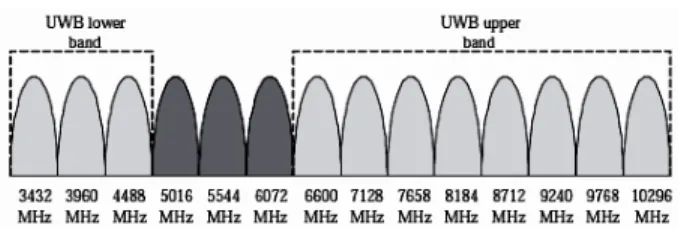
After the release for unlicensed uses of the Ultra-wideband (UWB) applications within the 3.1-10.6GHz frequency band by Federal Communications Commission (FCC) in 2002 [1], interest in UWB systems for short-range and high-data rate wireless communications has increased significantly. Among a few UWB technologies, the Multi-band (MB) OFDM technique receives strong attention for the implementation of very high data rate (up to 480Mb/s) wireless devices. This technique divides the 3-10GHz frequency band into several sub-bands of 528MHz, as shown in Fig. 1. This frequency plan shows good flexibility for the frequency regulations of different applications and can co-exist with 802.11a/b/g wireless systems, which use frequency bands around 5.2GHz showing in the dark area in the lower spectrum of the UWB band of Fig. 1. The carrier frequency is fast hopping between different sub-band channels and using OFDM modulation scheme to achieve fast data rate while each single channel is operating with a relative low speed rate.
Many papers have discussed the CMOS MB-OFDM frequency synthesizer design for direct-conversion UWB system [4-7]. However, these frequency synthesizers use multiple local oscillators (LO) to generate single carrier tones, which occupy large die area and consume large power
Manuscript received June 28, 2010. This work was supported by the Natural Sciences and Engineering Research Council of Canada (NSERC) under Grant Number STPGP 350545.
Anh Dinh is with the Department of Electrical and Computer Engineering, University of Saskatchewan, Saskatoon, Canada. (phone: 306-966-5344; fax:
306-966-5407; e-mail: [email protected]).
Xubo Wang is with the Department of Electrical and Computer Engineering,
University of Saskatchewan, Saskatoon, Canada. (e-mail:
due to the high frequency and wide-band nature of the design. In this paper, a MB-OFDM frequency synthesizer using 78% of the UWB spectrum is proposed, enabling data transmission in 11 sub-bands within four band groups (group 1, 3, 4, and 5) according to the frequency spectrum plan. The frequency synthesizer generates 11 carrier tones from a single independent reference frequency. The proposed architecture reduces the number of mixers and complexity of the circuitry.
Fig. 1. Frequency plan for OFDM UWB.
This paper is organized as follows. Section II presents the design architecture of the MB-OFDM UWB frequency synthesizer. Section III presents the circuit design of the synthesizer blocks, and design issues are discussed. Section IV provides simulations results of the frequency synthesizer. Finally the conclusions are drawn in Section V.
II. FREQUENCY PLANNING AND PROPOSED ARCHITECTURE
The frequency synthesizer serves as a crucial function of generating the carrier tone frequencies for up-conversion and down-conversion in a MB-UWB transceiver. The role of the frequency synthesizer as a part of the MB-UWB system is illustrated in Fig. 2.
Fig. 2. Frequency synthesizer in MB-UWB transceiver.
Due to the fundamental structural difference between an MB-OFDM UWB system and a narrowband wireless system,
Design of a 11-Band 3-10GHz Frequency
Synthesizer for Multi-Band OFDM UWB
Transceiver in 90nm CMOS Technology
the range of the carrier frequencies spans 7GHz, which makes the use a standard phase lock loop based (PLL) frequency synthesizer no longer suitable. Furthermore, to guarantee a fast and reliable data transmission rate, the switching time between different frequency tones should be less than 9.47ns according to the IEEE 802.15.3a standard guard interval time.
Table 1 shows the frequency planning for the direct conversion MB-OFDM UWB transceiver. The reference frequency fref of 8448MHz is chosen to generate the 11
frequency tones. The bandwidth of each frequency sub-band is 528MHz (i.e. each carrier frequency is 528MHz away from its adjacent carrier frequency). To reduce the complexity of the frequency synthesizer, the center frequencies (3960MHz, 7128MHz, 8712MHz, and 9768MHz) of each band groups are generated as the reference frequencies for their band groups. These reference frequencies further generate the adjacent frequency tones of the same band group through an up or down conversion of 528MHz.
Table 1: Frequency Synthesis for the 11 Carrier Tones
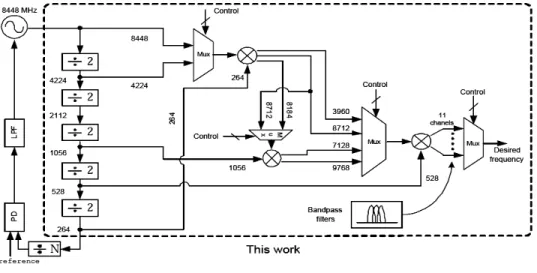
The proposed frequency synthesizer architecture generating 11 frequencies is shown in Fig. 3, which consists of five divide-by-2 circuits, three mixer, and three switching circuits. In this architecture, the employed dividers and mixers are broad-band since they are not optimized for a single input or output frequency. The bandpass filtering after mixers is used to allow only the desired frequency component to pass to the next stage. In the design, fref/16 is the lowest
frequency synthesized. A significant reduction in power and area could be expected due to the reduced number of mixers and VCOs and PLLs.
In the proposed architecture, the frequency 3960MHz, 8184MHz, and 8712MHz are obtained by either mixing fref
or fref/2 with 264MHz. Frequency 7128MHz and 9768MHz
are obtained by mixing fref/8 with 8184MHz and 8712MHz.
III. FREQUENCY SYNTHESIZER BLOCKS
A. The Divider
The frequency divider plays an important role in the high speed circuit. It is a crucial building block for generating different carrier tones from a single reference frequency of the VCO. The sinusoidal signal can not be divided down into other frequencies since it only contains one frequency component. In order to perform frequency division, the sinusoidal signal must be converted to digital square wave first. Then, after division at digital domain, the signal is low-pass filtered to obtain the desired sinusoidal waveform. There are three types of frequency dividers: (1) flip-flop based frequency divider, (2) injection-locked frequency divider (ILFD), and (3) regenerative frequency divider. The ILFD uses a VCO and the frequency is locked to a harmonic of the input frequency. The drawback of ILFD is it exhibits a very narrow frequency lock range. A regenerative frequency divider consists of a mixer and a low-pass filter in a closed loop feedback form. The regenerative divider performs a wider frequency range, but it must use a number of passive components which occupy a large chip area.
The divide-by-2 circuit in this frequency synthesizer adopts a current mode logic (CML) based D flip-flop using resistor loading for high speed operation as shown in Fig. 4 to perform frequency division. In Fig. 4, the two D flip-flops always operate periodically and alternately between sensing and latching mode, enabling the output frequency to be half of the input frequency. The track and latch modes are determined by the input signals to M1, M4 and M9, M12. When the input signal is high to turn on the transistors, the circuit operates in the tracking mode. Only looking at one flip-flop, the tail current flows entirely through the tracking circuit M2 and M3, allowing Q1N to track the input.
In the latch mode, the input is low and the tracking stage is disabled, when the latch pair is active to store the data at the output.
B. The Mixer
The mixer in this UWB frequency synthesizer is employed to generate the band frequencies by mixing two internal generated reference frequencies. A mixer circuit adopting the widely used double-balanced Gilbert cell topology for transconductance mixing and is shown in Fig. 5. The Gilbert cell is chosen since it provides reasonable conversion gain at high frequency, good rejection at the input ports, and a different output connection. The good rejection are achieved by cancellation of the undesired generated signal components by the out phase input components. M3 and M6 are the input port for Vin1, and M1 and M2 are the input port for Vin2.
Band Carrier Tone (MHz) Frequency Synthesis
1 3432 fref /2- fref /32- fref /16
2 3960 fref /2- fref /32
3 4488 fref /2- fref /32+ fref /16
4 6600 fref - fref /32- fref /8- fref /16
5 7128 fref - fref /32- fref /8
6 7656 fref - fref /32- fref /8+ fref /16
7 8184 fref - fref /32
8 8712 fref + fref /32
9 9240 fref + fref /32+ fref /32
10 9768 fref + fref /32+ fref /16
Fig. 3. Proposed MB-UWB synthesizer architecture.
Fig. 4. Frequency divider circuit
Fig. 5. Mixer circuit
C. The Switching Circuit
A frequency band selection switch must provide fast (less than 9.47ns) frequency switching between different channels. Differential pairs with switching NMOS are used to implement the band selection switches, as shown in Fig. 6. The cascade configurations provide good isolation between
voltage is high, the two upper nMOS transistors M3 and M4 in each differential pair are in active mode and the input signal is passed to the output node with a conversion gain. Digital control signals are used to turn on and turn off different frequency bands simultaneously.
Fig. 6. Switching circuit
D. The Bandpass Filter
A sixth order Chebyshev bandpass LC filter bank is placed after the mixing circuit to purify the signal and pass through the desired frequencies. The high order of the Chebyshev high-Q filters provide steeper roll-off and smoother response at pass-bands. A single bandpass filter circuit is shown in Fig. 7. The bandwidth of each filter is 200MHz, allowing some degrees of uncertainty of the generated frequency tone. A broadband amplifier is placed after the filter to increase the filter gain. In the design, 11 pass-bands are allocated at the frequency of 3432MHz, 3960MHz, 4488MHz, 6600MHz, 7128MHz, 7656MHz, 8184MHz, 8712MHz, 9240MHz, 9768MHz, and 10296MHz.
Fig. 7. Bandpass filter circuit
IV. FREQUENCY SYNTHESIZER SIMULATIONS
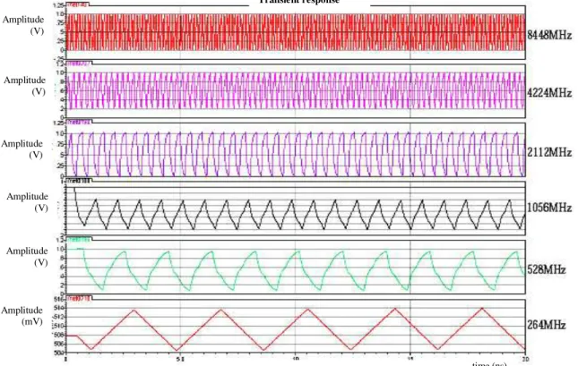
output signals generated by each frequency divide-by-2. The VCO output of 8448MHz is divided to 4224MHz, 2112MHz, 1056MHz, 528MHz, and 264MHz respectively.
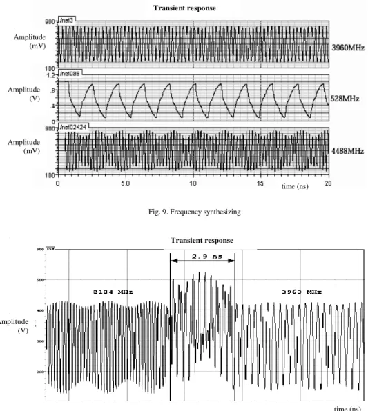
Fig. 8 shows the frequency synthesizer result for band 4 frequency of 4488MHz generated by mixing the adjacent frequency tone of 3960MHz and the 528MHz frequency signal. Most frequency components other than 4488MHz are attenuated by the bandpass filter. The slight modulation amplitude at 4488MHz appear in Fig. 9 suggests a minor impurity in the output, which may be caused by the nonlinearity of the circuits. Fig. 10 demonstrates the signal switching at the frequency synthesizer output between 8184MHz and 3960MHz. The simulated switching time is 2.9ns, well below the 9.47ns requirement of the IEEE 802.15.3a standard. The simulated average power consumption is 121mW with a power supply of 1.0V. Power consumption can be further reduced with careful design and power management.
V. CONCLUSION
A fully integrated MB-OFDM UWB frequency synthesizer was proposed, designed and simulated. The frequency synthesizer generates 11 bands covering UWB frequency from 3GHz to 10GHz. The frequency synthesizer operates in the band group 1, group 3, group 4, and group 5 with interference rejection at 5GHz, generating 11 carrier tones with fast hopping from a 8448MHz signal generated by a VCO. An efficient frequency planning is proposed to minimize the number of RF blocks. The simulated frequency tone switching time is 2.9ns. The average power
consumption is 121mW at a power supply of 1V. Simulation results demonstrate the feasibility of low cost, low power, fast switching UWB frequency synthesizer capable of using 11 bands in the designated UWB spectrum.
REFERENCES
[1] Federal Communications Commission, “FCC notice of proposed rule
making, revision of part 15 of the commission’s rules regarding ultrawideband transmission system,” FCC, Washington DC, ET-docket 98-153.
[2] JinKyung Kim, Sung-Kyu Jung, Ji-Hoon Jung, Sang-Kyung Sung,
Kang-Yoon Lee, Chul Nam, Sang-sung Choi, “A Design of the Frequency Synthesizer for UWB Application in 0.13um RF CMOS process,” 4th
IEEE International Symposium on Electronic Design, Test and Applications, Hongkong, January 23-25, 2008.
[3] Zue-Der Huang, Fong-Wei Kuo, Wen-Chieh Wang, and Chung-Yu Wu,
“A 1.5-V 3-10GHz 0.18um CMOS Frequency Synthesizer for
MB-OFDM UWB Applications,” Aerospace and Electronic System
Magazine, IEEE, January 2008.
[4] Behzad Razavi, “A UWB CMOS Transceiver,” IEEE Journal of Solid
State Circuits, Vol. 40, No. 12, December 2005.
[5] B. Razavi et al., “A 0.13um CMOS UWB Transceiver,” ISSCC Dig.
Tech. Papers, pp. 216-217, 2005.
[6] Jin He, Y. P. Zhang, “A CMOS Ultra-Wideband Impulse Radio
Transceiver for Interchip Wireless Communications,” IEEE
International Conference on Ultra-Wideband, ICUWB 2007, September 2007.
[7] T. Terada, S. Yoshizumi, M. Muqsith, Y. Sanada and T. Kuroda, “A
CMOS Ultra-wideband impulse radio transceiver for 1-Mb/s data
communications and ±2.5-cm range finding,” IEEE Journal of
Solid-State Circuits, Vol. 41, No. 4, pp. 891-898, April 2006.
[8] A. Bevilacqua, A. Niknejad, “An ultrawideband CMOS low noise
amplifier for 3.1-10.6 GHz wireless receivers,” IEEE Journal of
Solid-State Circuits, Vol. 39, No. 12, pp. 2259-2268, December 2004.
[9] T. H. Lee, The Design of CMOS Radio-Frequency Integrated Circuits,
1st ed., New York: Cambridge Univ. Press, 1998.
[10] J. Lee, and D. W Chiu, “A 7-band 3-8 GHz Frequency Synthesizer with
1ns Band-switching in 0.18um CMOS Technology,” ISSCC Dig. Tech. papers, pp. 204-2-5, Feb. 2006.
Fig. 8. Frequency division
Transient response
time (ns) Amplitude
(V)
Amplitude (V)
Amplitude (mV) Amplitude (V) Amplitude
Fig. 9. Frequency synthesizing
Fig. 10. Frequency switching
Transient response
time (ns)
Transient response
Amplitude (V) Amplitude
(V)
Amplitude (mV) Amplitude
(mV)