J. of the Braz. Soc. of Mech. Sci. & Eng. Copyright 2007 by ABCM January-March 2007, Vol. XXIX, No. 1 /115
Hellen dos R. Mourão
Valdir P. e Silva
[email protected] Escola Politécnica, University of São Paulo Dept. Structure and Foundations Eng 05508-900 Sao Paulo, SP. Brazil
On the Behaviour of Single-Span
Steel Beams Under Uniform Heating
Structures’ load resistance is reduced when subject to high temperatures in fire. Nevertheless, it is not enough to take into account strength and modulus of elasticity reduction. One must know with great accuracy the behaviour of the structures including the realistic boundary conditions at high temperatures, in order to determine for safe and of low cost solutions. This work is intended to analyse the behaviour of steel beams under uniform temperature rising. It covers beams under several uniform load levels and three boundary conditions: simply supported (pin-roller), simply supported with axial restraint (pinned-pinned) and both ends fixed (fixed-fixed). The variation of deflection, critical temperature, bending moment, normal force and stresses, with the temperature is presented. The analyses were made with the aid of ANSYS computer software taking into account material and geometric non-linearities and the variation of the stress-strain diagram with the temperature.
Keywords: fire safety, non-linearity, Ansys, structures, steel beam
Introduction
Thermal action is the action on structure described by means of the heat flux, by radiation and convection, caused by temperature differences between hot gases and structure parts (Eurocode 1, 2002). Exposure of materials to thermal action causes degradation of physical and chemical properties, reduction of strength and modulus of elasticity and produces additional loads on statically indeterminate structures. Fire situation is considered an accidental action as ABNT NBR 14323 (1999) (Silva and Fakury, 2002) and Eurocode 0 (2001). For this reason, the design actions have lower values than those normally adopted at room temperature. The level of loading in fire situation is, therefore, fundamental to check the structural safety.
The behaviour of structures in fire has been object of experimental and computational studies performed by several researchers such as: Rotter and Usmani of the University of Edinburgh (Rotter et all, 2000), Franssen of the University of Liege (Franssen, 2005), Bailey and Wang of the University of Manchester (Wang, 2002; Bailey, 2000), Fontana of the University of Zurich (Fontana and Knoblock, 2004), Vila Real of the University of Aveiro (Vila Real, 2003), Buchanan of the University of Canterbury (Buchanan, 2002), among others. Experimental analysis that was accomplished on the fire of an 8 story building in Cardington (U.K.), has strongly contributed to the research in this subject. The development of these studies helps the researcher to improve his structural understanding and contributes to such new field of
research of immediate practical usefulness.1
This work is a contribution to these studies. Its aim is to analyse the behaviour of statically determinate or indeterminate single span beams with local and global buckling prevention under high temperature and several loading levels. Another objective is to create didactic examples for the practice engineers and the students, in view of the different way that is used to solve this kind of problem. They are, evidently, basic structures that will serve as reference to more advanced studies of the authors.
Paper accepted. May, 2006. Technical Editor: Marcelo A. Savi.
Nomenclature
fy = characteristic value of yield strength, kN/cm2
kp,θ = y
, p
f θ
σ
is the proportional limit for steel reduction factor at
temperature θ , dimensionless
ky,θ= yield strength reduction factor at temperature θ ,
dimensionless
l = span of the beam, cm
Mfi,Rd = design value of the resistant bending moment in fire,
kN cm
Mfi,Sd = design value of the bending momen, in fire, kN cm
MRd = design value of the bending moment resistance of the
cross section at room temperature, kN cm
pfi,d = design value of the uniformly distributed load, kN/cm
Wel,x = elastic section modulus, cm3
Wpl,x = plastic section modulus, cm3 Greek symbols
α = coefficient of the thermal elongation (°C-1)
γa = the partial safety factor for steel at room temperature
(dimensionless)
γa,fi = 1is the partial safety factor for steel, in fire
(dimensionless)
∆θ = variation of the temperature (°C)
δl = horizontal displacement (cm)
η = “loading level” (dimensionless)
σp,θ is the proportional limit for steel (kN/cm
2
)
θ = temperature (°C)
Subscripts
a relative to steel
d relative to the design value el relative to the elastic regimen fi relative to fire
k relative to the characteristic value Sd relative to the design value of the action Rd relative to the design value of the resistance p relative to the proportional limit
pl relative to the plastic regimen x relative to the flexure axis y relative to the yield strength
θ relative to the temperature
Description of Models
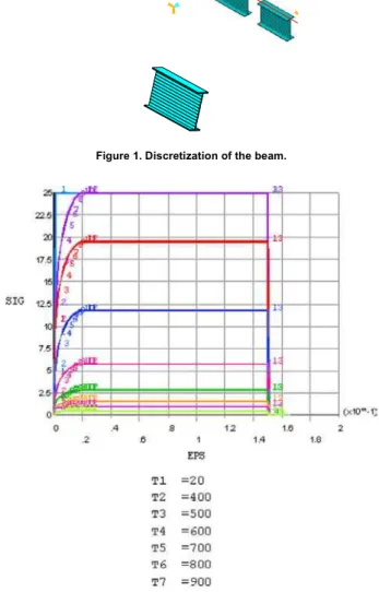
A computerised nonlinear finite elements analysis was performed with the software Ansys using the “beam 24” element. The beams were discretized in 50 to 70 elements along their length. Use of the “Beam 24” allows division along the height of the cross section in order to consider material’s non-linearity (Fig. 1). Material’s non-linearity was established by means of the stress-strain diagram seen in Fig. 2. The thermal expansion coefficient of steel was supposed to be constant with temperature and equal to 1,4
x 10-5 °C-1(Eurocode 3, 2003).
Three beams of “I” welded cross-section, 18 m span and further dimensions presented in Table 1 were analysed. These beams were studied for three support conditions according to Fig. 3.
Figure 1. Discretization of the beam.
Figure 2. Stress-strain diagram with the temperature, adopted in this work.
Table 1. Dimensions of the beams adopted in this work.
Dimensions Beam #1 Beam #2 Beam #3
bf (cm) 35 45 50
h (cm) 90 120 150
tf (cm) 1.25 1.6 1.6
tw (cm) 0.8 0.95 1.25
Height/span 1/20 1/15 1/12
(a) simply-supported beam (pin-roller)
(b) simply-supported beams with axial restraint (pinned-pinned)
(c) fixed ended beams (fixed-fixed)
Figure 3. Boundary conditions adopted in this work.
The beams were subject to an uniformly distributed load (pfi,d),
corresponding to the bending moment Mfi,Sd (Eqs. 1 and 2).
Rd Sd ,
fi M
M =η (1)
a y x , pl Rd
f W M
γ
= (2)
Where:
Mfi,Sd isthe design value of the bending moment, in fire
ηis a factor was varied from 0.1 to 1.0. Throughout this work,
ηwill be designated “loading level”.
MRd is the design value of the bending moment resistance of the
cross section at room temperature
fy is the chaacteristic value of yield strength
Wpl,x is the plastic section modulus
γa = 1.1is the partial safety factor for steel at room temperature
For each situation, the beams were analysed by the software Ansys, for temperatures varying in steps of 100ºC until the software no longer converged. Then, the steps were more refined until the software no longer converged due the plastic limit of the beams. The “Beam 24” element of the Ansys considers the efforts plastic redistribution but it doesn’t include lateral torsional or local bucklings analyses. The flexural buckling about minor principal axis of the cross section was prevented due the inclusion of lateral supports. The elastic critical force for the flexural buckling about major principal axis was not reached in these studies. Throughout this work, this final temperature is nominated “critical temperature”
The main representative results are showed in this paper. All results are presented in Mourão (2004).
Pinned-Roller Beams
We consider in this section beams with the dimensions taken from Table 1, with one support completely preventing longitudinal displacement and the other a roller support (Fig. 3a).
The simply supported beams #1, #2 and #3 were submitted to an
uniformly distributed load pfi,d according to Eq. 3.
pd,fi = ηηηηpRd
l =1800cm
pd,fi = ηηηηpRd
l =1800cm
pd,fi = ηηηηpRd
l =1800cm
bf
tf
J. of the Braz. Soc. of Mech. Sci. & Eng. Copyright 2007 by ABCM January-March 2007, Vol. XXIX, No. 1 /117 a
y x pl, 2 d fi,
f W 8
η
p
γ
l
= (3)
where
ηis the loading level
l is the span of the beam
Wpl,x is the plastic section modulus
fy is the characteristic value of yield strength
γa = 1.1 is the partial safety factor for steel at room temperature
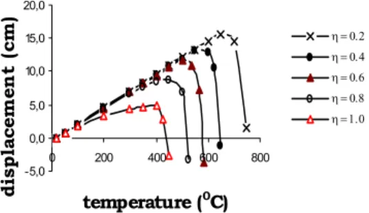
The values of deflection and horizontal displacement δl (Fig. 4)
for beam #2 are presented in Figs. 5 and 6.
Figure 4. Deflection and horizontal displacement of the pinned-roller beam.
-5,0 0,0 5,0 10,0 15,0 20,0
0 200 400 600 800
temperature (0C)
d
is
p
lacem
en
t (
cm
)
η = 0.2
η = 0.4
η = 0.6
η = 0.8
η = 1.0
Figure 5. Horizontal displacement with varying temperature and different load levels for beam #2.
-80 -60 -40 -20 0
0 200 400 600 800
temperature (°C)
d
e
fle
c
tio
n
(
c
m
)
η = 0.2
η = 0.4
η = 0.6
η = 0.8
η = 1.0
Figure 6. Deflection with varying temperature and different load levels for beam #2.
For relatively low temperatures, thermal expansion raises δl but
the reduction of material’s modulus of elasticity leads to a deflection rise (Fig. 6) which reverses the horizontal displacement at the support. The free support’s horizontal displacement of the simply supported beam varies linearly with temperature (Eq. 4) up to a certain temperature.
δl = lα∆θ (4)
where
δl is the horizontal displacement
α is the coefficient of the thermal elongation
l is the span of the beam
∆θ is the variation of the temperature
This temperature can be calculated, approximately, by means of geometric linear analysis (Eq. 5), considering Eq. 6 and that the stress is the proportional limit for steel at elevated temperature.
x el,
x pl, a p,
W W
η
k
γ
θ = (5)
where:
kp,θ= y
, p
f θ
σ
is the proportional limit for steel reduction factor at
temperature θ
σp,θ is the proportional limit for steel
fy is the characteristic value of yield strength
η is the loading level (Eq. 1)
γa = 1.1 is the partial safety factor for steel at room temperature
Wpl,x is the plastic section modulus
Wel,x is the elastic section modulus
After that, the horizontal displacement diminishes due to the beam deformation (Fig. 5). In actual situation, supports are not free to move. In general, in common structures, there is a partial restraint
to this displacement, what means that the value of δl will be smaller
than those presented in Fig. 5.
The critical temperature of beams, as defined at the end of 2.1, depends on the load level. This can be seen in Fig. 7.
Figure 7. Critical temperature with different load levels.
The critical temperature of beams can be calculated (Eurocode 3, 2003 or NBR 14323, 1999) by means of geometrically linear analysis, considering Eq. 6.
Mfi,Rd = Mfi,Sd (6)
Where
Mfi,Rd the design value of the resistant bending moment, in fire
Mfi,Sd the design value of the bending moment, in fire
From Eqs. (1), (2) and (3), having in mind that the strength
factor in fire situation is γa,fi = 1, we get Eq. 7.
a
, y k
γ η
θ = (7)
where
ky,θ the yield strength reduction factor at temperature θ
400 600 800 1000
0 0,2 0,4 0,6 0,8 1
c
ri
tic
al
t
e
m
p
er
at
u
re (
ºC
)
beam 1 beam 2 beam 3
η
δ
l
δ
l
l
η is the loading level
γa = 1.1 is the partial safety factor for steel at room temperature
The values presented in Table 2 confirm that the Eq. 5 leads to a fair approximation.
Table 2. Comparison between ηηηη and ky,θθθθ.
η θcr non-linear analyses
kyθ from θcr η/1,1
0,1 821,6 0,099 0,091
0,2 739,2 0,189 0,182
0,3 681,7 0,274 0,273
0,4 643,8 0,365 0,364
0,5 606,3 0,455 0,455
0,6 575,2 0,556 0,545
0,7 545,4 0,639 0,636
0,8 516,7 0,728 0,727
0,9 483,6 0,816 0,818
1 443,6 0,904 0,909
Figure 8 presents the bending moments at the mid span of beam #2 as a function of the temperature and the load level. Bending moment’s value has just a little alteration when compared to the one calculated by linear theory, because the relationship between support horizontal displacement and span length is small.
0 50000 100000 150000 200000 250000 300000
0 200 400 600 800
t e mpe r a t ur e ( °C)
η = 0. 2 η = 0. 4 η = 0. 6 η = 0. 8 η = 1. 0
Figure 8. Bending moment at the mid span of the beam #2 with varying temperature and different load levels.
0 2 4 6 8 10 12 14
-15 -10 -5 0 5 10 15
stress (kN/cm2)
h
e
ig
h
t o
f
th
e sect
io
n
20
100
200
400
600
606,2
Figure 9. Stresses of a section of the beam #2 with varying temperature, for ηηηη = 0.5.
Stresses variation at the most stressed section of beam #2, for
η = 0.5, can be seen in Fig. 9. As can be noted, the stress istribution
approaches to the one normally adopted as an ideal rigid-plastic hinge representation.
Pinned-Pinned Beams
We consider in this section beams with the dimensions taken from Table 1, with both supports completely preventing longitudinal displacement (Fig. 3b).
Figure 10 shows the support’s horizontal reaction of beam #2
and #3 against varying temperature and different load levels. One can note that the axial force increases initially up to a certain temperature and subsequently decreases because of the higher displacements.
-6000
-4000
-2000
0
2000
0 200 400 600 800
temperature (°C)
axial
f
o
rc
e
(
k
N
)
η = 0.2
η = 0.4
η = 0.6
η = 0.8
η = 1.0
(a)
-8000
-6000
-4000
-2000
0
2000
0 200 400 600 800
tem perature (°C)
a
x
ia
l f
o
rc
e
(
k
N
)
η = 0.2 η = 0.4 η = 0.6 η = 0.8 η = 1
(b)
Figure 10. Axial force with varying temperature and different load levels of the beam #2 (a) and beam #3 (b).
- 2 5 0 - 2 0 0 - 15 0 - 10 0 - 5 0 0
0 2 0 0 4 0 0 6 0 0 8 0
t e m p e r a t u r e ( ° C )
d
ef
lect
io
n
(
cm
)
(a)
- 12 0 - 7 0 - 2 0 3 0
0 2 0 0 4 0 0 6 0 0
t e m p e r a t u r e ( °C )
d
ef
lect
io
n
(
cm
)
(b)
Figure 11. Deflection with varying temperature and different load levels of the beams #2 (a) and #3 (b).
J. of the Braz. Soc. of Mech. Sci. & Eng. Copyright 2007 by ABCM January-March 2007, Vol. XXIX, No. 1 /119
When temperature rises, there is a lowering of this horizontal force due to the higher deflection. In consequence, the bending
moments and the compression stresses (σ/fy,θ) are lowered. For still
higher temperatures, the support reaction changes the direction of applied force lowering bending moments and increasing tensile stresses until reaching plastic collapse at a critical temperature. The critical temperature is higher than that found for a beam that has no restraint to axial displacement at the supports.
According to Mourão (2004), the value of support horizontal reaction of beam #3 is higher than that of beam #2 and this is higher than that of beam #1. This happens because the higher the moment of inertia, the lower the deflection of the beam.
Figure 11 presents deflection variation against the temperature and the load level for beams #2 and #3.
The critical temperature of pinned-pinned beams varies with the load level, as presented in Fig. 12. Beam #3, having higher moment of inertia and area than #1 and #2, reaches lower deflections and higher support reactions and therefore has lower critical temperatures.
Figure 12. Critical temperature with load level.
Figure 13 presents bending moments at mid span of the beams #2 and #3 against the temperature and the load level. One can note that the bending moment on pinned-pinned beams increases initially due to the support’s reaction, up to a certain temperature, and subsequently decreases as the support’s horizontal reaction is reduced with rise in temperature. This occurs because the higher displacements that depend on the temperature and the load level.
The stresses variation at the most stressed section of beam #2,
for η = 0.5, can be observed in Fig. 14. As can be noted, close to
critical temperature, tension zone takes the cross section almost thoroughly.
Bending moment diagrams presented in Figs. 15 and 16 show the alteration in the parabolic aspect caused by tensile reaction force.
Comparison Between Pinned-Roller and Pinned-Pinned Beams
Figure 17 shows a comparison between the deflection of beam #2 when simply supported without and with axial restraint, for the same load level.
0 50000 100000 150000 200000 250000 300000
0 200 400 600 800
temperature (°C)
be
ndi
ng
mom
e
n
t
(k
N
c
m
) η = 0.2
η = 0.4 η = 0.6 η = 0.8 η = 1.0
(a)
0 100000 200000 300000 400000 500000
0 200 400 600 800
temperature (°C)
b
e
nd
in
g m
o
m
e
nt
(k
N
cm
) η = 0.2
η = 0.4
η = 0.6
η = 0.8
η = 1
(b)
Figure 13. Bending moment at the center of the span of the beams #2 (a) and #3 (b) with varying temperature and different load levels.
0 2 4 6 8 10 12 14
-25 -20 -15 -10 -5 0 5 10 15 20 25
stress (kN/cm2)
he
ig
ht of t
h
e secti
o
n
20
100
200
400
500
700
741,1
Figure 14. Stresses of a section of the beam #2 with varying temperature for ηηηη = 0.5
X Y Z
Figure 15. Bending moment diagram of the beam #1 at ηηηη = 700 0 C.
η 500
600 700 800 00
0 0.2 0.4 0.6 0.8 1
X
Y
Z
Figure 16. Bending moment diagram of the beam #1 at ηηηη = 800 0 C.
-250 -200 -150 -100 -50 0
0 200 400 600 800
temperature (0C)
de
fl
e
c
ti
o
n (
c
m)
pinned-roller pinned-pinned
Q
Figure 17. Deflection of the beam #2 for ηηηη = 0.6.
Deflections are smaller for the pinned-roller beam due to the fact that support is allowed to move in the thermal expansion, i. e. without compression reactions.
400 600 800 1000
0 0.2 0.4 0.6 0.8 1
η ηη η
cri
ti
cal
t
e
mp
erat
u
re (
°C)
pin-rol beam 1 pin-rol beam 2 pin-rol beam 3
pin-pin beam 1 pin-pin beam 2 pin-pin beam 3
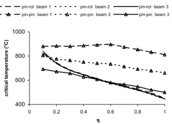
Figure 18. Critical temperature of the beams.
As one can observe in Fig. 18, pinned-pinned beams present critical temperature higher than pinned-roller ones. This occurs because at high temperatures the reactive forces on pinned-pinned beams become tension contributing to the rise of collapse temperature. Exceptions are the rare cases of very deep beams, lightly loaded. One concludes that beams that are considered to be isostatic, for as usual in practice for design purposes, have a true critical temperature higher than that determined by simplified methods that don’t take into account the axial restraint. Deflections of pinned-pinned beams are higher than those found on similar
beams with no restraints on axial strain, but with lower expansion velocity (cm/ºC) (Fig. 17).
In these simple examples, it was noted that thermal strains can cause significant increase of the internal forces in low temperature ranges that do not affect steel structures safety, because the design value of the load in fire situation is less than in room temperature (Silva, 2004). For higher temperatures, the increase in the forces is not substantial. Eurocode 3 (2001) generalises this conclusion and advises that, when ISO-fire method is used for evaluation of thermal action, these forces can be disregarded.
As one notes in Fig. 19, the support horizontal reaction, due to heating at fairly low temperatures, causes an increase of the bending moment on the pinned beam, when compared to the pinned-roller beam. The additional rising of the temperature causes the reduction of support reaction leading, consequently, to the reduction of the bending moment on the pinned-pinned beam.
0 50000 100000 150000 200000 250000 300000
0 200 400 600 800
temperature (°C)
ben
d
ing momen
t
(k
N
c
m
)
pinned-pinned beam 2 pinned-roller beam 2
Figure 19. Bending moments at the mid span of the beam #2.
Fixed-Fixed Beams
We consider in this section beams with the dimensions taken from Table 1, with both supports completely preventing displacements and rotation (Fig. 3c).
In order to consider an extreme support condition, the beams with fixed ends are analysed in this section. The beams #1, #2 and
#3 were submitted to an uniformly distributed load pfi,d according to
Eq. 8.
a y x pl, 2 d fi,
f W 12
η
p
γ
l
= (8)
where
pfi,d is the design value of the uniformly distributed load
η is the loading level
l is the span of the beam
Wpl,x is the plastic section modulus
fy is the characteristic value of yield strength
γa = 1.1 is the partial safety factor for steel at room temperature
Figure 20 presents horizontal reaction variation with the temperature and the load level. As is observed, the support horizontal reaction is a compression one. With the rising of the temperature, support reaction lowers slightly, keeps itself constant and, in continuation, lowers more steeply. The expansion, the deflection, although small, and the stiffness reduction are responsible for this behaviour.
J. of the Braz. Soc. of Mech. Sci. & Eng. Copyright 2007 by ABCM January-March 2007, Vol. XXIX, No. 1 /121
-6000 -5000 -4000 -3000 -2000 -1000 0
0 200 400 600
t e mpe r a t ur e ( °C)
η = 0.2
η = 0.4
η =0.6
η = 0.8
η = 1.0
Figure 20. Axial force with varying temperature and different load levels of the beam #2.
-35 -30 -25 -20 -15 -10 -5 0
0 100 200 300 400 500 600
t e mper a t ur e ( °C)
η = 0.2 η = 0.4 η = 0.6 η = 0.8 η = 1.0
Figure 21. Deflection with varying temperature and different load levels of the beam #2.
The geometric non-linearity has little influence on the deflection at room temperature (Mourão, 2004). However, when the beam is submitted to high temperature, non-linearity has a fair influence over the results (Fig. 22). In this case, for reference purposes only, the deflection of the “linear theory” was calculated for a modulus of
elasticity at 400ºC (14 350 kN/cm2).
0 10 20 30 40 50
0 0,2 0,4 0,6 0,8 1 η
def
le
c
ti
on
(
c
m
)
linear
non-linear
Figure 22. Deflection of the beam #1 at 400°C.
Figure 23 presents the variation of bending moment at mid-span of beam #2. One can observe that the bending moment rises with the temperature. This happens due to the rise of support reaction that is compression. The bending moment is higher for beam #3 than for #2 and higher for #2 than for #1. This rise of the bending moment value with the cross section occurs due to the rise in the support horizontal reaction. The stress variation at the most stressed section
of beam #2, for η = 0,6, can be observed in Fig. 24. As one can
note, at high temperatures, the compressed region takes the largest part of the beam’s cross section, due to horizontal reaction.
0 50000 100000 150000 200000 250000
0 200 400 600
temperature (°C)
be
ndi
ng mome
nt
(k
N
c
m
)
η = 0.2
η = 0.4
η = 0.6
η = 0.8
η = 1.0
Figure 23. Bending moment at the mid span with varying temperature and different load levels for beam #2.
0 2 4 6 8 10 12 14
-25 -15 -5 5 15
stress (kN/cm2)
hei
g
h
t o
f t
h
e
se
c
ti
o
n 20100
200
300
512,8
Figure 24. Stresses of a section of the beam #2 with varying temperature for ηηηη = 0.6.
X Y Z
1
Figure 25. Bending moment diagram of the beam #1 at θθθθ = 457.9 °C.
-5000 -4000 -3000 -2000 -1000 0
0 100 200 300 400 500 600
temperature (°C)
axi
al
fo
rce (kN)
pinned-pinned beam 2 fixed-fixed beam 2
Figure 25 shows the bending moment diagram near to the critical temperature. It keeps the shape of the diagrams at room temperature.
400 500 600 700 800 00
0 0,2 0,4 0,6 0,8 1
η ηη η
cr
it
ic
a
l t
e
m
p
er
a
tur
e
(°
C
)
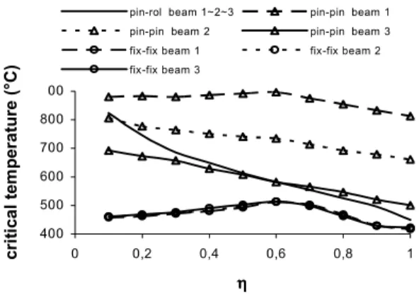
pin-rol beam 1~2~3 pin-pin beam 1
pin-pin beam 2 pin-pin beam 3
fix-fix beam 1 fix-fix beam 2
fix-fix beam 3
Figure. 27 Critical temperature of the beams with the load level.
Conclusions
The thermal deformations cause displacements if beams are not prevented from deforming and stresses if they are prevented. We have shown that properly characterizing support conditions of the structures in fire situations is fundamental, in order to search for safe and low cost fire safety design solutions.
The results of computational analysis of single span steel beams prevented from buckling out of plane and submitted to several loading levels, types of support and uniform temperatures were presented in this paper. In this analysis, geometric non-linearity, material non-linearity and variation of mechanical properties with the temperature were considered.
In the studied cases, one can conclude that:
For pinned-roller beams, the geometric non-linearity has very little influence on the value of critical temperature. The support’s horizontal displacement varies linearly with the temperature up to a certain limit, beyond which it lowers due to the large deflection of the beam. The variation of the stresses at the most stressed section, at nearly critical temperature, follows approximately the distribution conventionally adopted to represent an ideal plastic hinge.
Pinned-pinned beams subjected to fairly low temperatures are submitted to compressive stresses, due to thermal expansion. Therefore, due to temperature there is an increase of the deflection and bending moments. In the presence of a transverse loading and higher temperatures, the reaction force and in consequence, the compressive stresses and the bending moment are lowered due to the magnitude of the deflection. Rising the temperatures to still higher values, the support reaction tends to reverse its direction reducing the bending moments contributing to the rise of the critical temperature in most cases. Hence, the additional deflections due to temperature are higher for pinned-pinned beams in relation to pinned-roller beams due to reactions causing compression in the beam but their rate of growth with temperature is smaller. The
tensile stresses at the most stressed section, close to the collapse temperature, take the largest part of the beam’s cross section, due to the horizontal traction at the support.
Since often beams are considered statically determinate for design purposes, it should be remarked that they have a critical temperature higher than that calculated by simplified methods that do not take into account the axial tensile force which from large displacements.
In fixed-fixed beams, the deflections are much smaller and the compressive horizontal reaction in the high temperature range remains higher than in pinned-pinned beams.
Consequently, fixed-fixed beams have a lower value of critical temperature than pinned-pinned beams. Nonetheless, one must have in mind that the perfect fixed end is not found in practice. The effect of geometric non-linearity does not affect much the deflection at room temperature, but, if the beam is submitted to high temperatures, one can observe that non-linearity has great influence over the results, increasing the deflection. Near to the collapse temperature, the compressive stresses at the most stressed section of fixed-fixed beams take up most of the beam’s cross section.
References
ABNT NBR 14323, 1999, Dimensionamento de estruturas de aço de edifícios em situação de incêndio (Steel structures fire design), Associação Brasileira de Normas Técnicas (Brazilian Association of Technical Standard), Rio de Janeiro.
Bailey, C. G., 2000, Design of steel structures wit composite slabs at the fire limit state, Building Research Establishment, England.
Buchanan, A. H., 2002, Structural Design for Fire Safety, Wiley, England.
Eurocode 0, 2001. Basis of structural design Eurocode - Final Draft prEN 1990, European Committee for Standardization, Brussels.
Eurocode 1, 2002, Basis of design and actions on structures, actions on structures exposed to fire (parte 2.2), ENV 2002-2-2, European Committee for Standardization, Brussels.
Eurocode 3, 2003, Design of steel structures. Structural fire design, prEN 1993-1-2, European Committee for Standardization, Brussels.
Fontana, M. and Knobloch, M., 2004, Local Buckling Behavior and Strain-Based Effective Widths of Steel Structures, SIF’04 (Structures in Fire), Ottawa.
Franssen, J. M. and Zaharia, R., 2005, Design of Steel Structures Subject to Fire, Université de Liège, Liège.
Mourão, H. R., 2004 Sobre o comportamento de vigas de aço com flambagens impedidas, em situação de incêndio (The behavior of the steel beams, prevented from buckling, in fire). Dissertation of Master Degree presented to Escola Politécnica da Universidade de São Paulo. Sao Paulo.
Rotter, J. M. Usmani, A. S. Sanad and A. M. Gillie, M. . Structural Performance of redundant structures under local fire, article. Structures in Fire- Proceedings of the first International Workshop, School of Civil and Enviroment Engeneering, 2000 University of Edinburgh.
Silva, V. P. , 2004, Estruturas de aço em situação de incêndio (Steel structures in fire). Zigurate Editora. 176 p. Sao Paulo.
Silva, V. P. and Fakury, R. H., 2002, “Brazilian Standards for steel structures fire design”, Fire Safety Journal, vol 37/2, p. 217-227, Elsevier, Great Britain.
Vila Real, P., 2003, Incêndio em Estruturas Metálicas. Cálculo Estrutural, Edições Orion, Portugal