!"#$%&!# ' ( )
* *
+ , % +,
!!-!%&.! + / ' , ( )
!
"
!#
$ $ %&'
The machining parameter settings installed at CNC EDM machines are developed under optimum process conditions. Standard workpiece and electrode materials are used traditionally by machine manufacturers to establish the EDM parameter settings. However, this is not the usual situation of the tooling industry, where many different grades of workpiece and tool electrode materials are used. Consequently, the customers are required to develop their own process parameters, which normally demand many experimental tests. According to the aforementioned argument an experimental investigation on the EDM of AISI P20 tool steel under finish machining has been carried out. The tests were performed with graphite and copper as tool electrodes. Important EDM electrical parameters that influence the process performance were investigated. The measured technological outputs were the material removal rate Vw, volumetric relative wear ϑ and workpiece surface finish Ra . The main conclusions can be summarized as follows: the best results for material removal rate Vw were reached when EDM with negative graphite electrodes. Graphite and copper tools presented similar results of Vw for positive polarity. For graphite and copper tools the lowest values of volumetric relative wear were achieved for positive polarity. The best surface roughness Ra was obtained for copper electrodes under negative polarity.
Keywords: sinking EDM, graphite and copper electrodes, tool steel, process parameters
Introduction
1EDM has advanced to one of the major manufacturing
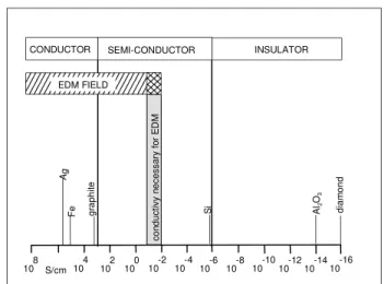
processes applied in die and mold making industry to generate three-dimensional complex cavities in many different classes of materials in rough and finish operations, as reported by König (1991). Examples include precision machining of materials such as hardened steels, carbides, ceramics and any other material that offers 0,01 S/cm of electrical conductivity, as depicted in Fig 1. Recently, other researchers (Amorim & Weingaertner, 2002, 2004) also reported that special aluminum-based alloys and copper-beryllium alloys, which are used to produce special injection molding tools, have also been machined by EDM. In addition, Masuzawa (2001) remarks that EDM is gaining more and more importance on the production of very accurate small parts (dimensions < 0,5 mm) on any electrical conductive material. This is a market trend known as Micro-EDM.
Figure 1. Electric conductivity necessary for EDM, König (1991).
Paper accepted August, 2007. Technical Editor: Domingos Alves Rade.
According to König et al. (1975) since the early stages of the
process of electrical discharge machining (EDM) by Lazarenko (1944) various causes for the material removal have been postulated. Kahng & Rajurkar (1977) have reported the electro-mechanical and thermo-electro-mechanical theories. The first theory suggests that a very high electric field is attributed to separate material particles of the workpiece as it exceeds the forces of cohesion in the lattice of the material. However, experimental evidence lacks supports to this theory. The second theory (thermo-mechanical) proposes that a variety of electrical effects of the discharge is responsible to the melting of material of the workpiece. Nevertheless, this theory does not agree with experimental results and then do not give a reasonable explanation for EDM phenomenon.
Nowadays, there is no complete and definite model explaining in all details the different processes that take place during a
discharge. As presented by several researches2 the best supported
theory still accepted to explain the electrical discharge machining of metals is based on the thermoelectric phenomenon. According to that theory the material removal in EDM is associated with the erosive effect produced when spatially and discrete discharges occur between two electrical conductive materials. Sparks of short
duration(0,1 to 3600 µs) are generated in a liquid dielectric gap
separating tool and workpiece electrodes.
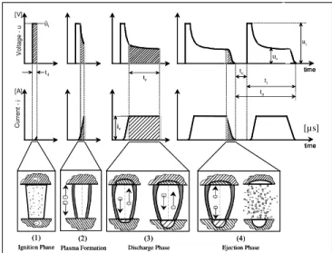
Figure 2 presents the phases of an EDM discharge. The four phases of a single discharge in EDM can be shortly presented as follows. The first one is the ignition phase. It represents the delay
time (td) to the occurrence of the breakdown of the high open circuit
voltage (ûi), applied across the working gap, until the fairly low
discharge voltage (ue). The second phase instantaneously occurs
right after the first one, when the current rapidly increases to the
operator specified peak current (îe). It is the formation of a plasma
channel surrounded by a vapor bubble. The third phase is the discharge phase. Here the high energy and pressure plasma channel
2 König & Klocke (1997), Eubank et al. (1993), Dibitonto et al. (1989), Mukund (1989), Van Dijck et al. (1974), Schumacher (1966), Müller (1965), Zolotyck (1955).
S
i
Ag
F
e grap
h
it
e
A
l2
O3
d
ia
m
o
n
d
c
o
n
d
u
c
ti
v
y
n
e
c
e
s
s
a
ry
f
o
r
E
D
M
EDM FIELD
S/cm
INSULATOR
CONDUCTOR SEMI-CONDUCTOR
100 10-2 10-4 10-6 10-8 10-1010-1210-1410-16 102
J. of the Braz. Soc. of Mech. Sci. & Eng. Copyright 2007 by ABCM October-December 2007, Vol. XXIX, No. 4 / 367
is sustained for a period of time (te) causing melting and evaporation
of a small amount of material in both electrodes. The fourth phase is the collapse of the plasma channel when the electric energy is turned off. This phase causes the molten material to be violently ejected.
At this time, known as interval time (to), a part of the molten and
vaporized material is flushed away by the flow of the dielectric across the working gap and the rest is solidified in the recently formed crater and surroundings. This process continues until the geometry of the workpiece is completely machined.
Figure 2. The phases of an electrical discharge in EDM (König & Klocke, 1997).
According to the aforementioned EDM theory the mechanical properties of the workpiece and the tool electrode have negligible effect on machining performance. However, the thermophysical properties of the workpiece and tool electrode (thermal and electrical conductivity, thermal expansion, heat to vaporize from room temperate, melting and boiling temperature) have considerable influence on the EDM process performance in terms of material removal rate, electrode wear and surface integrity of the workpiece.
Drozda (1998) reminds that the tool electrode is responsible to transport the electrical current to the workpiece. Therefore, any material to be used as a tool electrode is required to conduct electricity. In fact, there is a wide range of materials used to manufacture electrodes, for instance, brass, tungsten carbides, electrolytic copper, copper-tungsten alloys, silver-tungsten alloy, tellurium-copper alloys, copper-graphite alloys, graphite etc. In respect to the application of electrolytic copper and graphite as tool electrodes, the following arguments can be summarized :
(i) COPPER: it works very well as an electrode material and is widely used when smooth workpiece surface finishes are required. This material can be machined by all conventional methods such as drilling, turning, milling, grinding etc. But machining can be sometimes difficult because copper has a trend to drag on the edge of the cutting tool and the grinding wheel. In this case 2% Tellurium-copper alloy, which presents better machinability, can be a choice. However, copper machines on Wire EDM better than graphite. Very complex shapes can be obtained by Wire EDM onto copper electrodes. Another advantage of copper in comparison to graphite is its ability to be coined and then to be a very good material for engraving electrodes. For certain applications, such as electrodes to be used in medicine engineering field, copper is the best choice because of its facility to be highly polished.
(ii) GRAPHITE: this material is available in many different
grades from large grain sizes (200 m), used in rough EDM
operations, to very fine grains (1 m) for finish EDM operations, particularly in steel. The costs of graphite vary from inexpensive, for coarse-grain sizes, to very expensive for fine-grain sizes. It provides a high material removal rate and low electrode wear - depending on the EDM parameter settings - as compared to metallic electrodes. At the present there is a trend to incorporate the entire geometrical configuration of the workpiece onto a single large electrode, instead of partitioning the tool in many small pieces. Thus, the weight of the electrode becomes very important because it affects many factors in handling construction and use of the electrode. Graphite has a much lower density than copper, which makes it the best material for large electrodes. Although graphite is very abrasive it is relatively easy to be machined by all the conventional machining processes. Milling, drilling, turning, grinding and ultrasonic machining provide excellent finishes in graphite. The major drawback of graphite is the fine dust it produces during its machining. It is able to settle on the guides of the machine tool and when mixed with the machine's cutting fluid it will act like a lapping compound, which eventually reduces the accuracy of the machine. Precautions must be taken when machining graphite.
Vartanian & Rosenholm (1992) pointed out that for many years there have been discussions about the relative merits of the different EDM electrode materials. The major debates are about copper versus graphite. The EDM users in different parts of the world have been using different electrode materials to do exactly the same jobs. Normally, copper is mainly used in Europe or Asia for historical reasons. Graphite is the chosen material by the majority of EDM users from the United States of America. Most EDM jobs that can be done with copper can also be executed with graphite. The end result might be the same, but the cost to accomplish the job can be vastly different. In practical terms the choice of the electrode material will depend mainly on the tool size, the workpiece requirements, type of EDM machine and the methods of making the
electrodes. Other important factors shall be considered when
selecting the electrode material:
(a) Workpiece material removal rate Vw [mm3/min]: a correct
choice of EDM parameters to the pair tool /workpiece electrode
materials will increase the value of Vw.
(b) Electrode resistance to wear: there are four types of wear: volumetric, corner, end and side wear. Of the four, volumetric and corner wear are very important in finish EDM operations of fine details. Minimization of those wear requires choosing adequate EDM parameters and proper electrode material.
(c) Workpiece surface roughness: good workpiece quality is obtained by the proper choice of electrode material, good flushing conditions and adequate EDM parameter settings.
(d) Tool electrode material machinability: copper and graphite are the most commonly used. However, it is important to select an electrode material where the macro and microgeometry of the workpiece can be easily machined. It promotes reduction of machining time and costs.
(e) Tool electrode material cost: on average, fine graphite is about three times more expensive than copper. The choice shall be done considering the company facilities (e.g, machine-tools, CAD/CAM software technology etc). It also includes the know-how on machining copper and graphite electrodes, the complexity of the electrode and its difficulty to be redressed and the knowledge on EDM parameters.
The present work was focused in two major objectives. It is known that graphite is a relatively new tool electrode material to the Brazilian EDM users. Then the first objective was to provide technological information on the use of graphite when EDM steel workpieces in finish process conditions. The second objective was to attain more understanding about the EDM phenomena when machining with graphite electrodes in comparison to copper. It is
-+ + + + + + + + + + + + + + + + + + + + ++ + + + + -+ -+ -+ + -+ - -+-+ -+-+ +- +-+-+ -+ + --+- + -+ -+ + -+ -+ + -+ + -+ + + ++ + ++ + + + ++ + ++ + + + ++ + ++ + V o lt a g e u time time
(1) (2) (3) (4)
te
Ignition Phase Plasma Formation Discharge Phase Ejection Phase ie -+ + + + + + + + + + + + + + + + + + + + ++ + + + + -+ -+ -+ + -+ - -+-+ -+-+ +- +-+-+ -+ + --+- + -+ -+ + -+ -+ + -+ + -+ + + ++ + ++ + + + ++ + ++ + + + ++ + ++ + C u rr e
nt -
i
time
time
(1) (2) (3) (4)
td
te
to
ti
Ignition Phase Plasma Formation Discharge Phase Ejection Phase
because technological and basic research debates are still currently being carried out worldwide.
This research work is focused in assessing the finish EDM behavior of AISI P20 tool steel using a special grade of graphite and copper as electrodes. Important EDM electrical parameters that influence the process performance were investigated in terms of the following technological results:
(a) Material removal rate Vw: which represents the volume of
material removed from the workpiece per unit time [mm3/min];
(b) Volumetric relative wear ϑ: which represents the ratio of
electrode wear rate Ve to material removal rate Vw, expressed in
percentage values.
(c) Surface finish of the machined workpieces Ra [µm].
Nomenclature
îe = discharge current, A
tp = pulse cycle time, µs
pin = dielectric inlet pressure, MPa
ue = discharge voltage, V
td = ignition delay time, µs
ûi = open circuit voltage, V
te = discharge duration, µs
Ve = electrode wear rate, mm
3
/min
ti =pulse duration, µs
Vw = material removal rate, mm
3
/min
t0 = pulse interval time, µs
Greek Symbols
ϑ = volumetric relative wear (Ve/Vw), % τ = duty factor, dimensionless
Experimental Procedure
The Electrical Discharge Machining experiments were conducted at the Laboratory for Research on Machining Processes (LAUS) of the Pontifícia Universidade Católica do Paraná (Pontifical Catholic University of Paraná) (PUCPR), Curitiba-Brazil. The following materials, equipment and methods were applied for all the series of tests:
(i) EDM machine: a Charmilles ROBOFORM 30 CNC machine equipped with an isoenergetic generator, which means that is possible to set - among others EDM parameters - the discharge
duration te and to control the ignition delay time td as a percentage of
te. In this work td was kept as 30% of te for all the experiments
because a finish machining would be carried out. It means that low energy would be applied and then longer would be the ignition delay time.
(ii) Tool electrodes: 100 mm long cylindrical bars of graphite
and copper with diameter of 20 mm and a 4 mm central hole. The main specifications of the graphite used for the tests are 10 m
average grain size, 1,5 m average pore size, 1,77 g/cm3 density and
80 W/mK thermal conductivity. The tool electrodes were mounted axially in line with the workpiece samples as shown in Fig 3.
Figure 3. Geometry of the tool and workpiece samples.
(iii) Workpiece: AISI P20 tool steel square samples 25 mm wide
and 15 mm thick with a roughness Ra of 2µm on the surface to be
machined were prepared by Wire EDM, as shown in Fig.3. The workpiece material was chosen because it is widely used by the die and mold making industry. The surface finish was analyzed using a Surtronic 3 Taylor Hobson roughness measurement equipment. The measurements were done on the bottom of the EDM cavity using a
stylus tip of 5 µm, cut-off length of 0,8 mm and evaluation length of
4 mm.
(iv) Dielectric: hydrocarbon fluid for universal application in
EDM operations with properties of viscosity 3 CSt at 20 0C, flash
point of 125 oC, density of 0,783 g/ml and 0,3 % of aromates.
(v) Flushing method: the dielectric fluid was injected through the 4 mm electrode hole with 0,01 MPa providing adequate flushing of the eroded particles away from the working gap. In order to further improve the flushing efficiency an alternation between periods of machining U [s] and periods of tool electrode retraction with no discharges R [s] were introduced, as shown in Fig. 4. The values of U and R were defined after pilot tests.
time [s]
c
u
rr
e
n
t
-
i
U = 0,8 s U = 0,8 s
R = 0,2 s U
R
te
to + td
tool electrode
workpiece electrode
îe
Figure 4. Series of pulses U followed by a pause R [s].
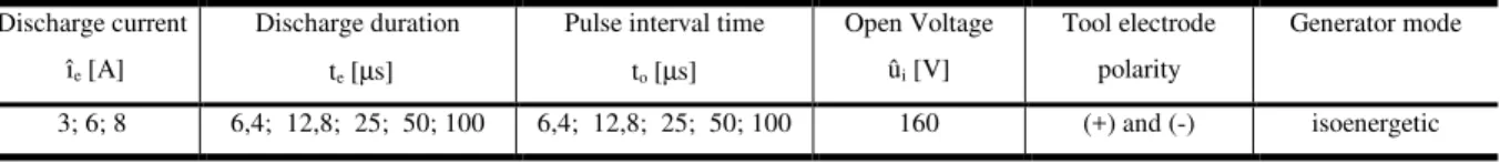
Table 1. Electrical variables used for the experiments with graphite and copper electrodes.
Discharge current
îe [A]
Discharge duration
te [µs]
Pulse interval time
to [µs]
Open Voltage
ûi [V]
Tool electrode
polarity
Generator mode
J. of the Braz. Soc. of Mech. Sci. & Eng. Copyright 2007 by ABCM October-December 2007, Vol. XXIX, No. 4 / 369
(vi) Electrical Variables: the major variables that influence on
the performance of EDM, which are discharge current îe, discharge
duration te and tool polarity (+/-), were investigated through the
values presented in Tab.1
In finishing EDM operations an important objective is to achieve the best workpiece roughness with a low level of volumetric
relative wear. So that it could be possible, the duty factor τ (ti/tp),
which represents the ratio between pulse duration ti and pulse cycle
time tp (tp = ti + t0), was chosen to be 0,5 for all the tests. This value
of τ, i.e., ti = to, was used because the good stability normally
observed on EDM for this condition. It means few occurrence of short-circuits and arc-discharges. As a consequence, proper flushing of eroded particles away from the working gap is promoted. Smaller
values of duty factor (ti < to) is commonly established by keeping ti
constant and increasing the value of to. This would lead to very low
discharges frequencies. It would result in decreasing the material
removal rate. On the other hand, levels of τ higher than 0,5 (ti> to),
set by reducing the value of to in relation to ti, would probably cause
an over-concentration of debris in the working gap. This would lead to non-uniform material removal along the frontal surfaces of the tool and the workpiece, as well as possible increase of the roughness.
The open gap voltage ûi has intrinsic relation with the size of the
working gap, i.e., the distance between the electrodes during the
spark. The higher is the value of ûi the larger the working gap. It is
common to set ûi at lower levels – 80, 100, 120 V - when EDM
under rough conditions. It is because the high average energy We =
ue . îe . te [J] keeps a larger working gap and proper expulsion of
debris. As the energy We is decreased so is the working gap size.
Thus, in finish EDM is recommended to establish higher values of ûi
in order to promote more adequate working gap. In this work, the
value of ûi = 160 V was established. This magnitude of ûi guaranteed
proper dispersion of the sparks along the frontal area of the electrodes and good flushing conditions.
(vii) The precise quantification of material removal Vw and
volumetric relative wear ϑ was possible using a precise balance
(resolution of 0,0001 g) to weigh the tool and workpiece before and after an average machining time of 30 minutes. The tests were done three times for each parameter settings, and no significant differences were observed among them. It is important to mention that during EDM process the graphite electrodes absorb some quantity of the dielectric fluid. To avoid any error when measuring the mass of the graphite tool it was necessary to carry out a drying
period. The electrodes were kept in a furnace at 400 oC for 24 hours
before and after each EDM test.
Results and Discussions
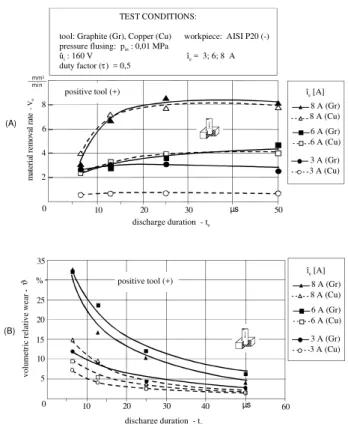
Figure 5A shows the results of material removal rate Vw for
positive graphite and copper tools versus the variation of discharge
duration te and discharge current ie. For both tool materials the
optimum discharge duration te was 50 µs at îe = 3, 6 and 8 A, where
the best results of Vw and good stability of the EDM were observed.
For îe = 6 and 8 A the values of Vw are similar for both materials,
reaching a maximum of 8 mm3/min. When EDM with graphite tool
at îe = 3 A the value of Vw was about 1,5 mm3/min higher than the
values of copper. This difference is not significant for EDM with finish parameter settings. The general performance of EDM is similar for the two electrode materials. Some tests with longer
discharge duration (te = 100 µs) were carried out, but the values of
Vw had a trend to deeply decrease for the two electrode materials.
Figure 5B depicts the results of volumetric relative wear ϑ
(Ve/Vw) for positive graphite and copper versus the variation of
discharge duration te and discharge current ie (3, 6, 8 A). When
EDMachining at the optimum conditions (te = to = 50 µs) graphite
presented an average value of volumetric relative wear ϑ of about 4
to 6% while copper has achieved 2%. Moreover, it is observed that
the volumetric wear ϑ is much higher for graphite than for copper
from te = 6,4 to 25 s, which represent very short levels of te and
interval time to. It probably occurred because the short interval times
to were not sufficient to efficiently flush the electrode and workpiece
debris away from the working gap. When EDM in finish conditions the working gap is very small, i.e. it varies from 10 to 50 m width (Drozda,1998). The grain size of graphite is essential to guarantee a stable EDM process. In this work a 10 m graphite grain size was used to carry out the experiments.
0 2 4 6 8
10 20 30 50
8 A (Gr) 8 A (Cu)
6 A (Gr) 6 A (Cu)
3 A (Gr) 3 A (Cu)
îe [A]
µs
mm3
min
discharge duration - te
m
at
er
ia
l
re
m
o
v
al
r
at
e
Vw
TEST CONDITIONS:
tool: Graphite (Gr), Copper (Cu) workpiece: AISI P20 (-)
pressure flusing: pin : 0,01 MPa
ûi : 160 V îe = 3; 6; 8 A
duty factor ( ) = 0,5τ
positive tool (+)
0 10 20 30 40 µs
discharge duration - te
60 10
5 15 20 25 35
positive tool (+) 8 A (Gr)
8 A (Cu)
6 A (Gr) 6 A (Cu)
3 A (Gr) 3 A (Cu)
îe [A]
v
o
lu
m
e
tr
ic
r
el
at
iv
e
w
e
ar
-
ϑ %
(A)
(B)
Figure 5. (A) Material removal rate Vw and (B) volumetric relative wear ϑϑϑϑ against the variation of discharge current îe and discharge duration te for EDM with positive graphite and copper electrodes.
Therefore, it is possible that particles separated of the tool electrode tended to clog the working gap, causing short-circuits and
arc-discharges. Thereafter this phenomenon has brought Vw to lower
levels and electrode wear rate Ve to higher levels. As a consequence
the volumetric relative wear ϑ (Ve/Vw) was increased when EDM
was performed with te = to from 6,4 to 25 s, as can be noticed at
Fig. 5B. Here it is possible to say that the 10 µm graphite grain size would probably give better results if applied to EDM with higher
rates of ie, te, to, when the working gap width would be larger and
the EDM performance could be more stable. It means that higher
Vw and lower ϑ would be reached.
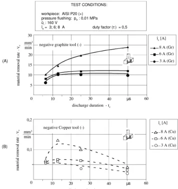
Figure 6A presents the results of material removal rate Vw when
EDM with negative polarity graphite tool (cathode). Despite the
values of discharge current ie and discharge duration te it is observed
that negative polarity for graphite promoted very much higher
values of material removal rate Vw than the ones achieved with
graphite at positive polarity (anode), as depicted before in Fig. 5A.
When EDM under the optimum discharge duration te = 50 µs
and ie = 8 A the maximum material removal rate Vw = 23,5
mm3/min was obtained for negative polarity, while for positive
graphite the maximum Vw =8 mm3/min was reached (Fig. 5A). This
and 6 A, where the maximum Vw about 10 mm3/min was reached
for te = 50 µs.
When comparing Fig. 6A against 6B, where Vw for negative copper
tools (cathode) are presented, the results of material removal Vw for
graphite versus copper are vastly different. In the case of copper the
maximum Vw was about 0,12 mm
3
/min when EDM with îe = 8A at
the optimum te = 12,8 µs, which is much lower than those of
graphite tools in any circumstances.
The performance of any electrical discharge machining operation greatly depends on the thermophysical properties of the
electrode material, although the non-thermal properties
(electrodynamical and mechanical effects) are not negligible. The
discharge current îe just takes place after the break down of the open
circuit voltage ûi. The occurrence of this phenomenon is just
possible when the cathode electrode starts to emit electrons. At this time, the electrons from the cathode collide with molecules of the dielectric fluid and more electrons are released together with positive ions. As a result, the dielectric fluid is vaporized and a high energy plasma channel is formed (Stevens, 1998). In addition, Drozda (1998) arguments that the cathode must be hot enough to permit electrons to absorb enough energy to escape. The thermophysical properties of copper are very different from graphite. When the cathode is copper it is able to emit electrons, to carry the current, only after some of its own material is melted and boiled. On the other hand, when graphite is the cathode it is able to emit electrons below its sublimation temperature. Therefore graphite is more stable than copper as cathodes, which promotes higher
material removal rates Vw, see Fig 6.
0 10 20 30 µs 60
discharge duration - te
40 5
10 15 20 30
mm3 min
m
at
er
ia
l
re
m
ov
al
r
at
e - V
w
3 A (Gr) 6 A (Gr) 8 A (Gr)
îe [A]
TEST CONDITIONS:
workpiece: AISI P20 (+) pressure flushing: pin : 0,01 MPa
ûi : 160 V
îe = 3; 6; 8 A duty factor ( ) = 0,5τ
negative graphite tool (-)
0 10 20 30 µs 60
discharge duration - te
40 0,1
0,2
negative Copper tool (-)
3 A (Cu) 6 A (Cu) 8 A (Cu)
îe [A]
mm3 min
m
at
er
ia
l
re
m
ov
al
r
at
e
V
w
(A)
(B)
Figure 6. Material removal rate Vw against discharge current îe and discharge duration te for (A) EDM with negative graphite tool and (B) for EDM with negative copper tool.
The results of workpiece surface roughness for copper and graphite tools at negative and positive polarity can be seen respectively in Fig. 7A and 7B. It is observed that negative graphite tool electrodes promoted higher roughness than copper tools for all
the three discharge currents (îe = 3, 6, 8 A) and discharge duration te
evaluated. For EDMachining using graphite at the optimum te = 50
s the Ra varied from 4 to 5 m, while copper tools provided much
better workpiece surface quality. The best value Ra = 0,6 m was
attained for îe = 3 A and te =12,8 s using copper eletrodes. The
higher surface roughness obtained with graphite is due to the higher
Vw reached for that material, which means that larger and deeper
craters were made in the workpiece surfaces.
Figure 7B depicts the results of EDM with positive polarity for both electrode materials. It is observed just a few divergences on the
results. When EDM with îe = 6, 8 A and the optimum discharge
duration te = 50 s the difference of Ra was about 1 m and for îe = 3
A a smaller difference occurred.
S
u
rf
ac
e
R
o
u
g
h
n
es
s
-
Ra µm
TEST CONDITIONS:
tool : Graphite (Gr) workpiece: AISI P20 (-)
pressure flushing: pin : 0,01 MPa
ûi : 160 V
îe = 3; 6; 8 A duty factor ( ) = 0,5τ
8 A (Gr) 8 A (Cu)
6 A (Gr) 6 A (Cu)
3 A (Gr) 3 A (Cu)
îe [A]
discharge duration - te
0 1 2 3 4 5
0 10 20 30 40 50 µs
positive tool (+)
(B)
S
u
rf
ac
e
R
o
u
g
h
n
es
s
R
a
µm
0 1 2 3 4 5
0 10 20 30 40 50
8 A (Gr) 8 A (Cu)
6 A (Gr) 6 A (Cu)
3 A (Gr) 3 A (Cu)
îe [A]
µs
discharge duration - te
negative tool (-)
(A)
Figure 7.Results of surface roughness when (A) EDM with negative and
(B) with positive graphite and copper tool electrodes.
In Figure 8 the results of volumetric relative wear ϑ for EDM
with negative electrodes are presented. The negative graphite tools
promoted much higher volumetric wear ϑ = 30% (îe = 8 A, te = 50
µs) than with EDM at positive polarity (ϑ = 6%, îe = 8 A, te = 50 µs
which represent the best parameter settings) as shown before in Fig. 5B.
0 10 20 30 40 µs
discharge duration - te
60 10
20 30 40 50 70
v
o
lu
m
e
tr
ic
r
el
at
iv
e
w
e
ar
-
ϑ %
8 A (Gr)
8 A (Cu) 6 A (Gr)
3 A (Gr)
îe [A]
TEST CONDITIONS:
tool: Graphite (Gr), Copper (Cu) workpiece: AISI P20 (+)
pressure flusing: pin : 0,01 MPa
ûi : 160 V îe = 3; 6; 8 A
duty factor ( ) = 0,5
negative tool (-)
τ
J. of the Braz. Soc. of Mech. Sci. & Eng. Copyright 2007 by ABCM October-December 2007, Vol. XXIX, No. 4 / 371
The same behavior is also noticed for negative copper tools at
their best EDM settings, i.e, for îe = 8A te = 12,8 µs the volumetric
relative wear ϑ is also about 30%. Although not represented in Fig.
8, when EDM with copper at îe = 3 and 6 A for the optimum te =
12,8 µs the volumetric relative wear of 40% was observed.
Conclusions
This work has carried out experiments on the performance of a special grade of graphite when electrical discharge machining AISI P20 tool steel under finish conditions. It has been investigated important EDM variables such as discharge current, discharge duration and tool electrode polarity. From the results of this work the following conclusions can be drawn:
(a) The highest material removal rates Vw were achieved for
EDM with negative graphite electrodes, much better than the results reached with copper tools. Therefore graphite is more stable than copper when EDM as cathodes.
(b) For electrodes at positive polarity, graphite and copper
presented similar results in terms of the values of Vw. Probably the
10 µm grain size of the graphite used for the experiments should be applied with higher discharge currents, when the working gap width would be larger and the EDM performance could be more stable. It
means that higher Vw and lower electrode wear ϑ would be reached.
(c) The lower levels of volumetric relative wear ϑ were attained
for EDM with graphite and copper at positive polarity despite the EDM parameter settings.
(d) The best surface roughness Ra was obtained for copper
electrodes under negative polarity.
References
Amorim, F. L. and Weingaertner, W. L., 2004, “Die-sinking electrical discharge machining of a high-strength copper-based alloy for injection molds”, Journal of the Brazilian Society of Mechanical Sciences, Vol. 26, No. 2, pp. 137-144.
Amorim, F. L. and Weingaertner, W. L., 2002, “Influence of duty factor on the die-sinking electrical discharge machining of high-strength aluminum alloy under rough machining”, Journal of the Brazilian Society of
Mechanical Sciences, Vol. 24, No. 3, pp. 194-199.
Crookall, J. R. and Khor, B. C., 1974 ”Electro-discharge surfaces”, 15th International Machine Tool Design and Research Conference, Birmingham, UK, [S.N], Vol.1, pp 373-384.
Dibitonto, D. D., et al., 1989, “Theoretical models of the electrical discharge machining process I: a simple cathode erosion mode”, Journal of
Applied Physics, Vol. 66, No. 9, pp. 4095-4103.
Drozda, T. J., 1998, “Tool and Manufacturing Engineers Handbook: Machining”, USA: Society of Mechanical Engineers, Vol.5.
Eubank, P. T., et al., 1993, “Theoretical models of the electrical discharge machining process III: the variable mass, cylindrical plasma mode”, Journal of Applied Physics, Vol. 73, No. 11, pp. 7900-7909.
Konig, W., 1991, “Advanced ceramics: sparks machine ceramics”. PMI, Vol. 23, No. 2, pp.96-100.
König, W. and Klocke, F., 1997, “Fertigungsverfahren - 3:Abtragen Und Generieren“, Berlin: Springer, Vol.3.
König, W., Wertheim, R., Zvirin, Y. and Roren, M., 1975, “Material removal and energy distribution in electrical discharge machining”, Annals
of the CIRP, Vol. 24, No. 1, pp. 95-100.
Lazarenko, B.R., 1944, “Die Elektrodenfunkenbearbeitung von Metallen”, Vestnik Maschinostroia, Moscou, Vol. 1, No. 1, pp. 25-36.
Masuzawa, T., 2001, “Keynote paper: micro-EDM”, ISEM 13th International Symposium for Electromachining, Bilbao, Spain, Vol. 1, pp.3-19.
Mironoff, N., 1970, “Introduction into the Study of Spark Erosion”, 2nd ed., Mirotecnic-Scriptor.
Mukund, R.; Barrufet, M.A. and Eubank, P. T., 1989, “Theoretical models of the electrical discharge machining process II: the anode erosion model”, Journal of Applied Physics, Vol. 66, No. 9, pp. 4104-4111.
Müller, H., 1965, “Beitrag zur klärung funkenerosivervorgänge”,
Elektrowärme, Germany, Vol. 23, No. 3.
Schumacher, B.M., 1966, “Das leistungsverhalten und der werkzeugverschleiss bei funkenerosiven bearbeitung von stahl mit speicher und impulsgeneratoren”, Doctorate Thesis - WZL- Laboratorium für Werkzeugmaschinen und Betriebslehre der RWTH-Rheinisch-Westfälischen Technischen Hochschule, Aachen, Germany.
Stevens, L., 1998, “Improvement of surface quality in die-sinking EDM”. Doctorate thesis - Department of Mechanical Engineering, K.U. Leuven, Belgium.
Van Dijck, F., et. al., 1974, “Some results of physical research in EDM”, 4th International Symposium for Electromachining, Bratislava, Poland, Vol. 1, pp.68-85.
Vartanian, M.A. and Rosenholm, O., 1992, “Methods of manufacturing” Manufacturing Conference, Chicago, USA. Vol. 1, pp 1-16.
Zolotyck B.N., 1955, “Physikalische Grundlagen Der