Laboratory study of dynamic mechanical characteristic of granite
subjected to confining pressure and cyclic blast loading
Abstract
To investigate the deformation characteristic of deep rock under cyclic blasting, the static-dynamic loading experimental equipment was set up. The dynamic strain gauges and high-speed HS camera were adopted to obtain strain field and the crack propagation of rock under confining pressure of 0 MPa, 5 MPa and 10 MPa. Under the one-time loading from cylindrical charge, the cracks in crushed zone were generated by shear and tensile failure. Circumference compressive stress is formed around borehole by confining pressure, and it reduces the circumference tensile failure by blast loading. The number of radial cracks and broken radius reduce with confining pressure increase. The reflected stress wave drives the existing fissures further developing. When specimens subjected to cyclic loading from PETN Cord, the rock is controlled by elastic deformation and no damage appeared after the first loading. With the cycle-index increase, the accumulation of plastic strain is observably when the strain exceeds the elastic limit strength of rock. The cumulative damage is nonlinear increased under cyclic loadings. The existing flaws or radial cracks run through specimen when the cumulative damage exceeds the material's yield strength.
Keywords
Rock mechanics; cyclic blast loading; confining pressure; deformation characteristic; damage accumulative evolution.
1 INTRODUCTION
With the increasing of deep tunnel engineering and underground resources exploitation, the dynamic response of deep rock subjected to the cyclic blast loading becomes complicated. Unlike surface rock, underground rock located in the environment with high in-situ stress, for instance, the vertical in-situ stress rise up to 27 MPa at a depth of 1000 m and the horizontal part can be approximately 13.5 MPa Brown & Hoek, 1978 . When rock mass subjected to dynamic cyclical loading such as impact loading and blast loading, a few of micro cracks are generated after initial loading. Then micro cracks grow and merge each other under subsequent loading, the damage accumulation caused the material failure completely at last Li et al., 2011; Ramulu, Chakraborty, & Sitharam, 2009 . Under the action of static and cyclic blasting, the deformation behaviour and failure mechanisms of rock are complicated Figure 1 . Therefore, the study of dynamic mechanical characteristic and cumulative damage of deep rock under cyclic blasting is essential.
Chenglong Hea*
Jun Yangb
a College of Mechatronics Engineering, North
University of China, Taiyuan 030051, China. E-mail: [email protected]
b State Key Laboratory of Explosion Science and
Technology, Beijing Institute of Technology, Beijing, China. E-mail: [email protected] *Corresponding Author
https://doi.org/10.1590/1679-78254424
Figure 1: Sketch of the loading state of underground rock.
The attenuation of shock wave from cylindrical charges has been investigated. The properties of the explosive, rock materials and coupling media would influence the failure process of rock. Generally, the explosion loading consists of shock waves and explosion gases, both of them play important place in the dynamic response of rock Onederra, Furtney, Sellers, & Iverson, 2013 . High Shock waves are generated initially and quickly spread to the borehole wall, the micro cracks appear due to shear band interconnection under extremely high pressures. As a result, the zone closed to the blast hole is crushed and pulverized. The tensile stress follow by compressive stress wave and drive the existing radial cracks developing. The fragmentation became more seriously by reflected waves along the boundary zone. Finally, the subsequent explosion gases flow into existing cracks, and then cracks run through specimen at last Cho & Kaneko, 2004; Eason, 1963; E. L. Liu, He, Xue, & Xu, 2011; Rathore & Bhandari, 2007 .
In previous studies, the MTS-815 rock test system, drop hammer experiment, and split hopkinson pressure bar SHPB were adopted to investigate the damage accumulate of rock under cyclic loading. When the loading was less than the threshold value of salt rock, three stages including initial deformation, constant velocity deformation and accelerating deformation were divided to describe the dynamic response process. Meanwhile the fatigue failure of salt rock was also controlled by static loading by confining pressure, and the axial strain and cycle-index at failure increased with the frequency by experimental study on MTS-815 test system Guo et al., 2011; J. Liu, Xie, Xu, & Yang, 2008 . The dynamic fatigue strength reduced with loading frequencies and amplitude, and the dynamic modulus increased with loading frequency Bagde & Petroš, 2005 .
Poisson’s ratio was attributed to the dilatant and viscoelastic, and strain rates increased with an increase in the maximum applied stress Ma et al., 2013 . Lin, Chen, and Liu 2005 adopted the drop-weight test to analyze the confining pressure effect of rock, concluded the damaged by cyclical impact loading were obviously, and the existence of confining pressure also increased the ability of rock against impact damage.
For the SHPB experimental investigation, Ge, Yu, Lu, & Ren, 2003 focused on the strain of fatigue failure corresponding to the maximal cyclic load, and reported the relation between the ability of resistance against cyclic impacts and cycle-index was from slow development to sharp decline. Wang, Xu, Liu, and Wang 2016 carried out the physical tests on red-sandstone free from and after 10, 20, 30, and 40 artificial TS cycles. The results showed that mineral loss and cement weakening lead to the increase of porosity and decrease of strength during the TS weathering process. The dynamical mechanical properties were improved with the increase of strain rate under impact loading. When the axial compression was 0, 65%, 87%, the ability of resistance against cyclic impacts dropped constantly during the whole cyclic loading Jin, Xi-Bing, Yin, & Kun, 2012 .
Although numerous studies were carried out on mechanical properties of rock under the coupled static and impact loads, these works were limited to test the dynamic behaviour of rock material under impact loading SHPB or Drop-weight test . It is well-known that the strain rate of rock under blasting is higher than that of impact loading. The stress wave from blast loading is gradually reduced during propagation. Therefore, this paper adopted the cyclic blast loading and investigated the deformation behaviour and damage accumulation in granitic with different confining pressures 0 MPa, 5 MPa, 10 MPa . The dynamic strain gauges, high-speed cameras HS and digital image correlation DIC were used to quantify the dynamic response and observe crack propagation process. At first, the fracturing process with different confining pressures under one-time blast loading is studied. Then the failure process and damage accumulation of rock under the cyclic loading are investigated. Some useful conclusions are given at last.
2 EXPERIMENT 2.1 Rock materials
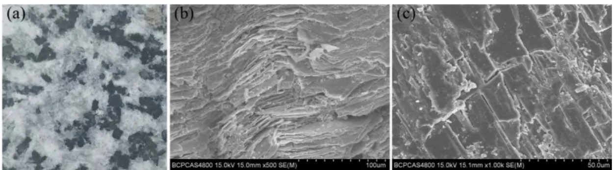
component elements in Fang Shan granite. The properties parameters of granite were as follows: average density 2.70 g/cm3, Poisson’s ratio 0.23, P-wave velocity 3738 m/s, Young's modulus 40.6 GPa.
Figure 2: Specimens and SEM images. a Photograph of rock sample; b SEM on 100 μm; c SEM on 50 μm.
The quasi-static properties of granite were tested using the WDW-300 electronic universal testing machine in the Laboratory of Explosion at the Beijing Institute of Technology Beijing, China . The cylindrical specimens were cut into Φ 50 25 mm and Φ 50 100 mm for tension and compression quasi-static test, respectively. The BX 120-4AA strain gages sensitive grid size is 4 2 mm were used to collect deformation during loading. The rock specimen was compressed at a speed of 0.2 mm/s and t strain signals were recorded on 2 /s. The stress-strain curves were given in Figure 3, the tensile strength of granite is 6 MPa 700 με and compressive strength is 86 MPa 2100 με . Both the tensile and compressive stress curves drop sharply after stress reach the maximum stress, that indicate the brittle fracture should be responsible for the failure of granite specimens in quasi-static experiment.
Figure 3: Stress-strain of FangShan granite in the quasi-static test results.
Figure 4: The dynamic stress-strain curves from SHPB results.
2.2 Test system and equipment
The experiment equipment mainly includes the servo pressure system, experimental platform and test system, as shown in Figure 5. In the first part, the hydraulic actuator provides pressure for jacks to simulate the in-situ stress conditions, the high-pressure oil pipe and pressure gage are used to control the pressure value accurately. The experimental platform consists of four correcting wedges, two jacks, four baseboards and outer frame. The pressure acted on the cylindrical specimen is uniformly by the correcting wedge. To observe crack growth and capture the dynamic deformation of rock, the High-speed camera and strain test are introduced, respectively. The strain field is calculated by VIC-2D base on the photographs from High-speed camera. The TTL signal is selected to trigger the camera and strain gauge simultaneously.
Figure 5: Schematic diagram of equipment. a Test system; b Photograph of experiment equipment.
Many factors should be considered before designing the experiment, such as the specimen geometry size, explosive types and uncoupling factors. The fragments and spall cracks caused by reflected tension waves should be removed from the free surface. Because the diffusion of explosion gas reduces the sharpness of photographs from HS, the nonpenetrative borehole was designed to prevent the explosion gas overflowing from the bottom of the borehole.
The selection of charge and specimen size can reference the previous experiment. Simha, Fourney, and Dick 1984 experimented with Plexiglas sheets 305 305 50 mm , and the PETN charge was 0.5 g and 10 g/m. Mchugh 1983 used a Plexiglas cylinder sample on Φ 300 300 mm, the PETN charges had diameters of 3.2 mm 4 g/m . Banadaki and Mohanty 2012 experimented with cubic samples 150 150 150 mm , and the diameters of PETN cylindrical charges were 1.1~2.23 mm 1.2~5.3 g/m . Rathore and Bhandari 2007 tested blasts in limestone blocks 550 300 250 mm at the laboratory scale by using the detonating cord with 8.5 g/m.
and B was used to remove reflected waves in the strain sensor surface Figure 6 . Five strain gages were pasted with a spacing of 12 mm, and the nearest gage was located on 28 mm. The center borehole was drilled on 10 mm in diameter. The distance between the DIC surface and the hole bottom was 10 mm. The PETN Charge and detonation cord were used for one-time loading and cyclic loading in experiment, as shown in Table 1. The copper tube with 1.5 mm thick was tightly installed in the borehole to prevent explosion gas penetrating into fissure.
Figure 6: Schematic diagram of sample.
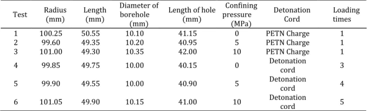
Table 1: Parameters of two detonations.
Detonation Diameter mm Density g/cm3 density g/m Linear VOD m/s
PETN Charge 2.80 1.0 6.15 6500
PETN Cord 1.98 1.3 4.00 6850
In this study, six groups of specimens were performed in the Laboratory of Explosion at the Beijing Institute of Technology. Tests 1~3 were conducted to study the failure process under blast loading with different confining pressures 0 MPa, 5 MPa and 10 MPa . Tests 4~6 were to investigate the effects of cycle-index on damage accumulative evolution under cyclic blast loadings. The electric discharge method was used to inspire the synchronization trigger system. The specimens in tests 4~6 were failure completely after 3, 4, 5 loadings, respectively, as shown in Table 2.
Table 2: Parameters of six tests.
Test Radius mm Length mm Diameter of borehole mm
Length of hole mm
Confining pressure
MPa
Detonation
Cord Loading times
1 100.25 50.55 10.10 41.15 0 PETN Charge 1
2 99.60 49.35 10.20 40.95 5 PETN Charge 1
3 101.00 49.30 10.35 42.00 10 PETN Charge 1
4 99.85 49.75 10.00 40.15 0 Detonation cord 3
5 99.90 49.55 10.00 40.90 5 Detonation cord 4
6 101.05 49.90 10.15 41.00 10 Detonation cord 5
Figure 7: Parameters of high-speed camera.
Figure 8: Photographs of specimen. a Strain test surface, b HS test surface, c Detonation cord, d Two parts.
3. RESULTS AND DISCUSSION
3.1 Dynamic response under one-time loading
Three stages were clearly found in strain-time curve after detonation Figure 9 . The first high frequency oscillation represented the strain signal was influenced by the ionization interference during detonating, and it last 70 μs. The second part was the dynamic deformation of rock under stress wave by blasting, and it last 30 μs. The propagation velocity of stress wave is 3738 m/s in rock sample, the test points at different position almost rose up at 150 μs. When incident stress wave spread to the free boundary of sample, the reflected waves was produced and the strain rose again under the secondary loading. The explosion gases loading was ignored because the copper tube can prevent gas flowing into fissures.
The yield strength of rock under blasting is higher than it in SHPB experiment the rock material become stronger with strain rates increase . The material around borehole is crushed by extremely high pressure with higher strain , and the damage zone away from borehole is produced by tensile failure with lower strain . The tensile strength from SHPB results are used as the failure criteria when analyze the failure process by hoop tensile in the explosion experiment. The average strain 0.002 on the descending part of tensile stress-strain curve is selected as the fracture strain, and the peak strain 0.0005 on linear part is used as the ultimate elastic strain.
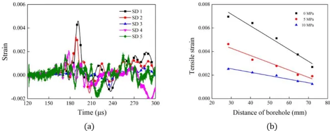
Figure 10 shows the hoop strain-time in test 2. The strain on SD 1 rose up to 0.0046 at 190 μs, it exceeded the tensile failure strain and micro fissures were produced near borehole. Then the deformation sharply decreased as stress wave propagated, the strain peaks of SD 4~5 were less than 0.002, and more dates were collected in Table 3. The attenuation of tensile strain is plotted in Figure 10 under different confining pressures. When the confining pressure was 0 MPa, the strain on 30 mm exceeded 0.007, the damage and fissures were formed by shear and tensile failure. With confining pressure increased to 5 MPa, the strain reduced 0.0046, the plastic deformation in the damage zone was weakened gradually. The strain was linear attenuated with distance increased. When the confining pressure was 10 MPa, the elastic deformation played a dominating role during blasting, and the confining pressure reduced the tensile failure by shock wave.
Figure 10: a Strain-time curve under 5 MPa confining pressure; b Attenuation of tensile strain.
Table 3: Peak strain under different confining pressures.
Test SD1 SD2 SD3 SD4 SD5
1 0.0070 0.0064 0.0051 0.0037 0.0027
2 0.0046 0.0033 0.0027 0.0021 0.0019
3 0.0025 0.0022 0.0020 0.0015 0.0012
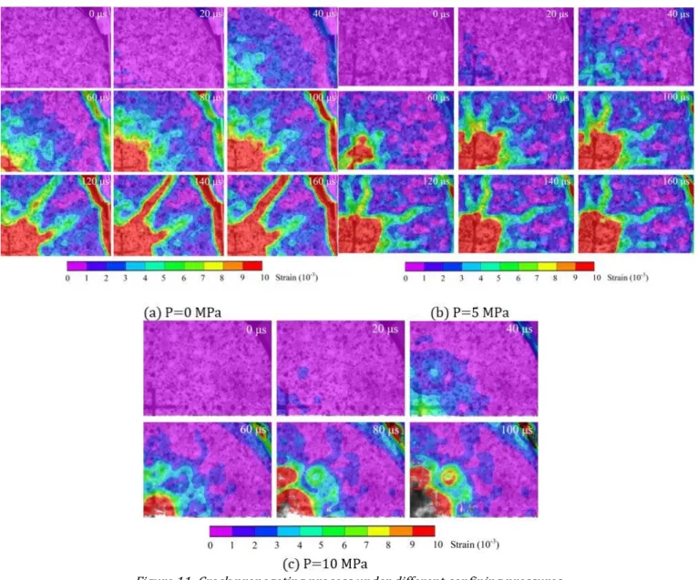
Using the strain gages with a higher sampling rate can capture the deformation of rock by stress wave, and HS technique is more easily to observe crack growth due to the crack propagation speed is less than stress wave. Figure 11 clearly displays the evolution of strain field on the HS test surface under different confining pressures, and the interval between adjacent photos is 20 µs. The time shown in the top right corner is started at the deformation of specimen. Initial stress wave from borehole propagated along the radial direction at 0~40 μs. The pressure of stress wave gradually was decreased in propagation. When the initial stress wave arrived boundary at 40 μs, the reflected stress wave were produced and strain concentration appeared on the upper edge. The strain concentration band extended to the boundary at 160 µs.
together with detonation products overflowed from the bottom at 100 μs, more explosive energy escaped from the central zone. The tensile failure by shock wave was gradually decreased as confining pressure increased.
Figure 11: Crack propagating process under different confining pressures.
Figure 12: Crack distribution on free surface under 0 MPa, 5 MPa, 10 MPa.
Figure 13: Broken zone on strain gauge surface under 0 MPa, 5 MPa, 10 MPa.
A micro crack in the damage zone is observed by SEM with different magnifications, as shown in Figure 14. A horizontal crack develops along the meander line and stop on the boundaries of mineral particles. In the vicinity of the crack surfaces, the fragmented rocks are generated and the intergranular cracking occurred under the dynamic loading.
Figure 14: SEM micrographs of fracture surfaces. a SEM on 1 mm. b SEM on 100 μm. c SEM on 10 μm.
3.2 Dynamic response under cyclic loadings
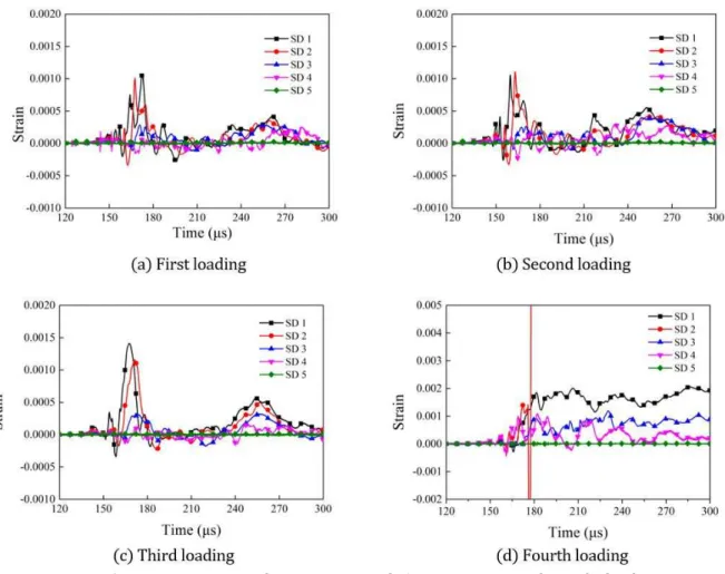
Figure 15: Strain-time curve of target points with 5 MPa pressure under cyclic loadings.
Table 4 lists the strain peaks during 150 μs~300 μs in test 4~6, and specimens are failure after 3, 4, 5 loadings, respectively. “--” represents the strain data is not recorded.
Table 4: Strain peak in test 4~6 under cyclic loadings.
Test 4 5 6
Cyclic
loadings L 1 L 2 L 3 L 1 L 2 L 3 L 4 L 1 L 2 L 3 L 4 L 5 SD 1 0.0017 0.0026 0.0057 0.0010 0.0011 0.0014 0.0021 0.0009 0.0012 0.0015 0.00291 0.0142 SD 2 0.0015 0.0019 0.0041 0.0011 0.0010 0.0012 0.0085 0.0009 0.0010 0.0011 0.0016 0.0064 SD 3 0.0006 0.0013 0.0032 0.0003 0.0002 0.0004 0.0012 0.0001 0.0002 0.0003 0.0009 0.0060 SD 4 0.0011 0.0015 0.0030 0.0001 0.0003 0.0002 0.0011 0.0001 0.0001 0.0002 0.0020 0.0056 SD 5 0.0023 0.003 0.0050 -- -- -- -- 0.0008 0.0022 0.0041 0.0078 --
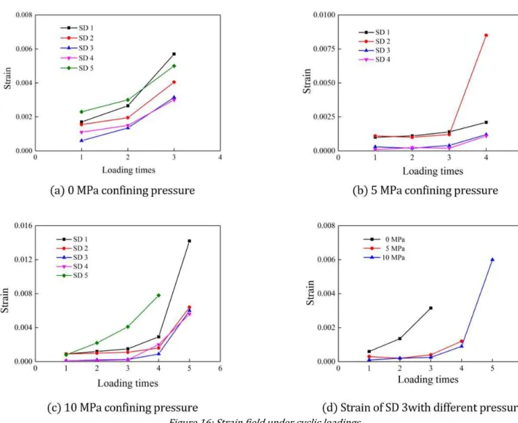
Figure 16 presents the deformation accumulation under cyclic loadings. The strain peak rose with loading times, and the deformation was largest without boundary constraint. As shown in Figure 16a, the deformation on SD 5 was bigger than other points. This phenomenon was ascribed to the tensile fracture by reflected wave. After the third loading, the neatest point SD 1 rose up to 0.006 and the irreversible failures have been produced.
Because the reflected wave had little effect on deformation in the middle zone, the SD 3 was selected to explored damage accumulation process. As shown in Figure 16d, when the confining pressure increased from 0 MPa to 5 MPa, the tensile failure from the shock wave reduced. This tendency is not significantly as confining pressure rose up to 10 MPa. Elastic distortion and accumulated damage were not obviously under earlier cyclic loadings, and then became seriously after plastic deformation appeared.
Figure 16: Strain field under cyclic loadings.
Rathore and Bhandari 2007 established the elastic damage coupled with crack propagations in strain space based on continuum media theory, the damage of rock is calculated by plastic strain. At first loading, the rock material is mainly controlled by elastic deformation and no damage appeared. When the strain peak exceeds the elastic limit strength of rock, the accumulation of plastic strain increases and the permanent deformations are generated. At last, the plastic strain reach the fracture strain
(ε )
f and the material is damaged completely. Whenthe plastic deformation happened in the material, the damage can be calculated as:
p e
p
p e
f
p f
0 (ε
ε )
ε
(ε
ε )
ε
1 (ε
ε )
D
D
D
Where D represents damage,
ε
pis the strain peak,ε
e is the ultimate elastic strain,ε
f is fracture strain. Accordingto the SHPB experimental results,
ε 0.0005, ε 0.002.
e
f
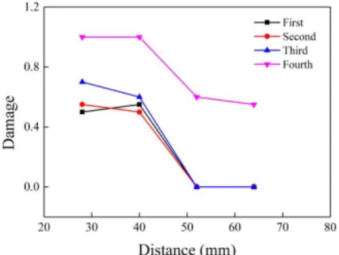
The process of damage accumulation under cyclic blasting in test 5 is listed in Figure 17. Under the first loading, the damage near the borehole was more than 0.4 and micro fractures were produced by plastic deformation. As loading times increased, the accumulation of damage was observably within 40 mm from explosive source, and the further zone beyond 50 mm was mainly controlled by elastic deformation. After the forth loading, the damage value on 42 mm increased from 0.6 to 1.0 and rock material was complete failure. The results illustrated that the damage accumulation nonlinearly increased under cyclic loadings.
Figure 17: Damage accumulation under cyclic loadings in test 5.
Figure 19: Specimen failure process in Test 4.
Figure 19 clearly exhibits the failure process in test 4 under the third blast loading. The deformation were produced by stress waves before 160 µs, then the-explosion gases with high pressure and temperature flowed out from central borehole during 160 µs~320 µs. The deformation cannot be analyzed in the later stage due to the explosive gases reduced the sharpness of the photos.
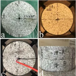
Figure 20: Crack distribution. a Test 4; b Test 5; c Test 6; d e Damage pattern of test 5 on longitudinal profile.
Figure 20 shows the fractures and damage pattern in three tests by experimental photographs. The diameter of central damage area was 100 mm in test 4, the collapses phenomenon caused by the reflected tension wave was seriously. Two visible radial cracks appeared in vertical direction and ran thought specimen, the width of bigger one was 2 mm Figure 20a . As shown in Figure 20b, the central damage area decreased to 40 mm in diameter because the initial confining pressure 5 MPa reduced the circumference tensile failure. Only one fissure can be observed in the top right corner. When confining pressure rose up to 10 MPa, the central damage zone was not extended, one indistinct radial crack located on the top left corner Figure 20c . As shown in Figure 20d and Figure 20e, the copper tube was not destructed after four blast loadings and the wall of borehole was smooth. The results indicated the explosion gas products did not flow into the junction surface, and the strain signals from strain gages were mainly caused by stress wave. Notably, the spallation was observably on the top and bottom surfaces, and the phenomenon was caused by the combined action of the initial wave and reflected tension wave.
4 CONCLUSIONS
measurement techniques were used to observe the crack propagation and test the dynamic deformation under different confining pressures, respectively.
Under the one-time loading from PETN cylindrical charge with a small diameter, cracks around borehole were generated by shear and tensile failure under the extreme pressure. The radial cracks were primarily produced by circumferential tensile stress from shock wave. Circumference compressive stress was produced by confining pressure, and it reduced the tensile failure by explosive loading. The number and size of radial cracks reduced significantly with confining pressure increase from 0 MPa to 10 MPa. With the distance increase, the strength of explosion shock wave reduced and confining pressure prevented cracks from growing.
When rock subjected to cyclic loadings from PETN Cord, the specimen was controlled by elastic deformation and no damage appeared after the first loading. Then the accumulation of plastic strain increased when strain exceeded the elastic limit strength of rock. Damage slowly increased with cycle-index increased, the damage increased sharply and specimen failure completely after the last loading. The damage accumulation was nonlinear increased as loading times increased, and the existing flaws or radial cracks further extend under cyclic loading and ran through specimen finally.
Notice that the micro cracks developed along the meander line and intergranular cracking occurred under the dynamic loading, the microstructures were observed in the SEM results.
References
Bagde, M. N., & Petroš, V. 2005 . Fatigue properties of intact sandstone samples subjected to dynamic uniaxial cyclical loading. International Journal of Rock Mechanics & Mining Sciences, 42 2 , 237-250.
Banadaki, M. M. D., & Mohanty, B. 2012 . Numerical simulation of stress wave induced fractures in rock.
International Journal of Impact Engineering, 40 2 , 16-25.
Brown, E. T., & Hoek, E. 1978 . Trends in relationships between measured in-situ stresses and depth. International Journal of Rock Mechanics & Mining Sciences & Geomechanics Abstracts, 15 4 , 211-215.
Cho, S. H., & Kaneko, K. 2004 . Influence of the applied pressure waveform on the dynamic fracture processes in rock. International Journal of Rock Mechanics & Mining Sciences, 41 5 , 771-784.
Eason, G. 1963 . Propagation of waves from spherical and cylindrical cavities. Zeitschrift Für Angewandte Mathematik Und Physik Zamp, 14 1 , 12-23.
Ge, X., Yu, J., Lu, Y., & Ren, J. 2003 . TESTING STUDY ON FATIGUE DEFORMATION LAW OF ROCK UNDER CYCLIC LOADING. Chinese Journal of Rock Mechanics & Engineering, 22 10 , 1581-1585.
Guo, Y. T., Zhao, K. L., Sun, G. H., Yang, C. H., Hong-Ling, M. A., & Zhang, G. M. 2011 . Experimental study of fatigue deformation and damage characteristics of salt rock under cyclic loading. Rock & Soil Mechanics, 32 5 , 1353-1359.
Jin, J. F., Xi-Bing, L. I., Yin, Z. Q., & Kun, D. U. 2012 . Effects of axial pressure and number of cyclic impacts on dynamic mechanical characteristics of sandstone. Journal of China Coal Society, 37 6 , 923-930.
Li, H., Xiang, X., Li, J., Jian, Z., Bo, L., & Liu, Y. 2011 . Rock damage control in bedrock blasting excavation for a nuclear power plant. International Journal of Rock Mechanics & Mining Sciences, 48 2 , 210-218.
Lin, D. N., Chen, S. R., & Liu, Y. P. 2005 . Experimental Study on Confining Pressure Effect of Rock Damage Under Cyclical Impact Loading. Mining & Metallurgical Engineering, 25 4 , 12-15.
Liu, E. L., He, S., Xue, X., & Xu, J. 2011 . Dynamic Properties of Intact Rock Samples Subjected to Cyclic Loading under Confining Pressure Conditions. Rock Mechanics & Rock Engineering, 44 5 , 629-634.
Liu, J., Xie, H., Xu, J., & Yang, C. 2008 . Experimental study on damping characteristics of rock under cyclic loading.
Ma, L. J., Liu, X. Y., Wang, M. Y., Xu, H. F., Hua, R. P., Fan, P. X., . . . Yi, Q. K. 2013 . Experimental investigation of the mechanical properties of rock salt under triaxial cyclic loading. International Journal of Rock Mechanics & Mining Sciences, 62 9 , 34-41.
Mchugh, S. 1983 . Crack extension caused by internal gas pressure compared with extension caused by tensile stress. International Journal of Fracture, 21 3 , 163-176.
Onederra, I. A., Furtney, J. K., Sellers, E., & Iverson, S. 2013 . Modelling blast induced damage from a fully coupled explosivecharge. Int J Rock Mech Min Sci, 58 58 , 73-84.
Ramulu, M., Chakraborty, A. K., & Sitharam, T. G. 2009 . Damage assessment of basaltic rock mass due to repeated blasting in a railway tunnelling project – A case study. Tunnelling & Underground Space Technology, 24 2 , 208-221.
Rathore, S. S., & Bhandari, S. 2007 . Controlled Fracture Growth by Blasting While Protecting Damages to Remaining Rock. Rock Mechanics & Rock Engineering, 40 3 , 317-326.
Simha, K. R. Y., Fourney, W. L., & Dick, R. D. 1984 . Studies On Explosively Driven Cracks Under Confining In-Situ Stresses.
Wang, P., Xu, J., Liu, S., & Wang, H. 2016 . Dynamic mechanical properties and deterioration of red-sandstone subjected to repeated thermal shocks. Engineering Geology, 212, 44-52.
Zhang, Q. B., & Zhao, J. 2014 . A Review of Dynamic Experimental Techniques and Mechanical Behaviour of Rock Materials. Rock Mechanics & Rock Engineering, 47 4 , 1411-1478.
Erratum
In the article Laboratory study of dynamic mechanical characteristic of granite subjected to confining pressure and cyclic blast loading, doi number: https://doi.org/10.1590/1679-78254424, published in journal Latin American Journal of Solids and Structures, 15 5 :e44, page 1:
Where it reads:
Chenglong Hea
Jun Yanga*
a State Key Laboratory of Explosion Science and Technology, Beijing Institute of Technology, Beijing, China. E-mail:
[email protected], [email protected] * Corresponding Author
It should read:
Chenglong Heª*
Jun Yangb
ª College of Mechatronics Engineering, North University of China, Taiyuan 030051, China. E-mail: [email protected]
b State Key Laboratory of Explosion Science and Technology, Beijing Institute of Technology, Beijing, China. E-mail: [email protected]