Performance of infill stiffened steel panel against blast loading
Abstract
In blast loading, out-of-plane behavior of infill wall is activated initially. Con-trary to other types of infill wall such as brick or concrete wall, infill steel plate wall exhibits more ductility. Since blast impulsive loading suddenly ex-erts a large amount of kinematic energy to infill wall, energy absorption characteristic of the infill wall should be taken into account, especially for protection of vulnerable buildings. Out-of-plane ductility of infill steel plate reduces the transmitted impulsive loading to the structure. In present study, out-of-plane behavior of infill steel panel has been studied as a sacrificial el-ement. In-plane behavior of infill steel panel is also investigated as a lateral bearing system. In-plane action should satisfy both resistance and perfor-mance criteria. In this research, finite element analysis, including geometric and material nonlinearities is used for optimization of the steel plate thick-ness and stiffeners arrangement to obtain more efficient design for plane and in-plane actions. The results of analyses show that for out-of-plane action, the plate thickness and stiffeners arrangement can be deter-mined such that on one hand, the impulse transmission can be minimized, and on the other hand, the maximum residual deformation can be limited to the predefined damage level. Additionally, the effect of stiffener arrange-ment on the performance of in-plane are studied and some practical rules have been derived for designing the infill steel panel against blast.
Keywords
blast loading, in-fill stiffened steel panel, ductility, performance level, trans-mitted impulse, plate buckling.
1 INTRODUCTION
In typical buildings, the first structural members exposed to the blast loading are the infill walls. In addition, in many actual cases it has been observed that infill walls breakdown due to shock wave causes irreparable injuries and damages while a proper design can prevent or to a great extent decrease serious failure. In such cases, a familiar solution is ductile details. The review of literature shows that using the aspect of ductility can result in a more efficient design. Ductility of structures in ultimate loading is a principle of design in structural engineering like stiffness. Actually, ductility is the ability of a structure or a part of structure to deform in plastic range such that some portions of stiffness remain. Aspect of ductility of structures has been the main topic of research especially in structural seismic design field. Ductility and energy dissipation of steel shear wall along with its initial large stiff-ness for reduction of story drift and also its proper performance in relatively strong earthquakes has proved a proper alternative of other lateral load bearing systems in seismic design. Several researches have been conducted to investigate the behavior of steel shear walls with different assumptions of details. In an analytical-experimental study, Takahashi et al. (1973) for the first time examined the effect of different arrangements and the rigidity of stiffeners on energy absorption and the buckling modes of steel plate. A large number of researches reviewed by R.G. Driver (1997) have evaluated the interaction between steel shear walls and other jointed structural elements. Astaneh-Asl (2001) conducted an overview of past uses of steel shear walls and a comprehensive study on ductile and brittle failure modes, and related design provisions. Recent studies by Asl and Safarkhani (2017) have focused on achieving more efficient details through developing energy absorbing capabilities of steel plate or its connection with boundary elements in addition to modification of details for decreasing undesirable failure modes in boundary elements. Ductility aspect is also an important point in every design against impulsive loading. Several studies have been conducted for determining the nonlinear effects of materials in structural members subjected to shock loading by single degree of freedom approach. Baker et al. (2012) summarize a collection and completion of studies. After
Hassan Ostadhossein a
Saeid Lotfi a*
a Department of Civil Engineering, University of Kashan, Kashan, Iran.
E-mail: [email protected], [email protected]
*Corresponding author
http://dx.doi.org/10.1590/1679-78254429
conducting several tests, Smith and Hetherington (1994) concluded that structures with low ductility were vulner-able to blast loadings. Mendis and Ngo (2003) examined the tall concrete structures against blasts and concluded that ductility was an important factor beside stiffness. They asserted that the reason for the reduction of destruction as a result of blast in World Trade Center in 1994 was the structural system ductility. Majority of injuries in blast loading happens due to brittle parts breakage and the resulting projectiles. Researches on the behavior of infill walls, as a part of structure, against shock loading has also been considered in several studies. Panel walls are used as the protective cover of steel structures in industrial buildings including petrochemical plants. ASCE publication (2011) for the design of blast resistant buildings in petrochemical facilities has an overall review on the character-istics of metal panel walls and discusses both the resistance and ductility of metal panel walls with different thick-ness and configurations qualitatively. Also, ASCE petrochemical blast design guidelines emphasizes on the im-portance of tensile in-plane resistance of cold formed penals rather than flexural behavior, especially against ex-plosions with an intensity greater than 14-28 kPa. Furtheremore, it underlines the importance of panel edges con-nections for the prevention of plate tearing. In this manual, steel plate deformation limitations for achieving the desired response have been determined similar to other structural members. The research conducted by Dipaolo and Woodson (2006) from the Army Corps of Engineers in the United States and by Salim et al. (2005) at The Air Force Research Laboratory revealed that steel wall studs had high resistance against severe blast loads. Stewart et al. (2014) have explained results of full-scale test on infill steel panels stiffened by stud with a special attention to connection details for mitigating the blast effects. Tavakoli and Kiakojouri (2014) worked on the nonlinear dynamic response of square steel stiffened plates under blast loadings. After studying various stiffener configurations, they concluded that addition of more stiffeners decreased the plastic energy meaningfully.
Infill steel panel has been used as a blast resistant member in recent decades. In a study conducted by Moghimi and Driver (2015) on steel shear wall systems, it was stated that after providing P-I curves for a steel panel re-sponse, the performance of shear wall was illustrated against several types of explosions and it was useful for pre-liminary design. They also pointed that steel shear wall had high-energy dissipation. They focused on in-plane be-havior of steel plate as a shear wall. Another important role of infill walls is its ability to depress the blast loading as much as possible, without imposing serious damage to the main structure. Steel panel as the front part of struc-ture, on the other hand, have to mitigate the impulsive loading as much as possible and then transmit the load through a proper path leading to lateral resistance system in order to restrain the damage to members without lateral resistance. In general, structural infill systems are classified into concrete, brick and metal infill walls. In this research, out-of-plane behavior of infill steel panel is introduced as a sacrificial element against blast, which will be deformed in plastic range, to minimize transmitted energy to the main structure. An essential question is how to achieve a more ductile design of an infill steel panel. To answer the research main question, several analyses have been performed to obtain the relationship between the details of stiffeners and response of steel panel for out-of-plane and in-out-of-plane behavior. Selected criteria for the comparison of different details are residual plate deformation as an indicator of damage level and also the ratio of output impulse to the input impulse, which is an index of ability of panel wall to isolate the impact shock. It has been concluded that the ductility of steel infill in both out-of-plane and in-plane behavior depend on the plate thickness, stiffener arrangement as well as their stiffness. This issue is investigated by considering both material and geometric nonlinearities. The effect of high velocity loading and strain rate as well as damping effect are also considered. The research conclusions can be used as a number of applicable recommendations for infill steel panel design. It is also concluded that stiffeners can be arranged such that the formation of plastic points is increased in order to improve the out-of-plane response of steel plate. The stiffener arrangement can also affect the infill buckling pattern for in-plane behavior and prevention of tension field which causes excessive strength. Such strength is not essentially desirable and may cause brittle failure and quick drop-down of strength.
2 BLAST LOADING SPECIFICATIONS
as-sumptions is very low. Another fact is that the reflection of incident wave from the surface causes wave charac-teristics to be changed. Therefore, the blast loading time history should be modified to a loading, which is prescribed by peak of reflected overpressure and equivalent time duration. According to ASCE publication (2011), it is allowed to apply the triangular equivalent blast loading instead of reflected overpressure time history, which is resultant of incident and reflected waves combination. Therefore, in present research three types of equivalent blast loading with low, medium and high peak blast pressures are considered, regardless of charge weight and stand-off distance. Regarding the common loadings in actual design cases, three types of triangular blast loading have been as-sumed in the analyses of this research with different intensities, regardless of the source of explosion characteris-tics. According to table 1, overpressure peak of the first loading is 70 kPa with related equivalent time duration of 20 msec. The second loading has the peak of 350 kPa and the duration of 20 msec while the third loading has the peak of 700 kpa with the same duration.
3 STRUCTURAL SYSTEM WITH STEEL INFILL PLATE AGAINST BLAST
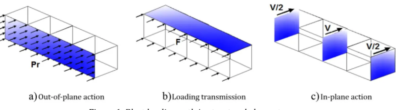
The structural system, which studied in this research, consists of steel infill wall in front of explosion wave. Steel wall is the first structural element exposed to impulsive loading. It is obvious that the Loading path through other structural elements directly depends on infill plate boundary conditions due to such loading. In case of con-necting the infill wall to the structural columns, a large portion of blast loading transmits to the columns and loss of columns occurs due to reduction of buckling resistance. Consequently, progressive collapse may occur. El-sanadedy et al. (2014) have studied this issue considering a steel structure with masonry infill. So, for reducing the risk of columns loss, no constraint is considered parallel to vertical edges of infill wall in this research. The latter advantage of connecting only the upper and lower edges of infill wall to top and bottom floor diaphragm is that the overpressure imposed by out-of-plane action of infill wall transfers to horizontal rigid floor diaphragms. As it can be seen in Figure 1, F is the load per unit length. It is applied to the floor diaphragm as a reaction to out-of-plane behavior, and in accordance with the previous description, impulsive load is proportionally distributed throughout the steel infill as a shear wall. Thereafter in-plane behavior of the steel infill wall will be activated; as shown in Figure 1-c.
The boundary conditions for in-plane behavior of infill panel as a shear wall is also considered equal to the out-of-plane behavior ones in order to separate the gravity bearing from lateral forces resistant systems. Predicting a gap between columns and the steel panel has a serious after-effect. Pressure leakage to the internal spaces of the building may precede the separation of infill panels due to large deformation against blast, causing personal injuries and damage to architectural components (Dusenberry (2010)). To avoid this disadvantage, using a flexible rubber filler with a suitable detail, between steel panel and columns is recommended.
Figure 1: Blast loading path in structural elements.
In general, the matter of details of steel panel being connected to boundary elements is critical for ensuring that the ductility capacity of steel panel is fully activated. According to recommendations of design for blast re-sistant buildings in petrochemical facilities ASCE (2011), proper attention should be paid to the connection details of steel plate and the supporting structural members to avoid tearing of steel plate as a result of stress concentra-tion.
4 MATERIAL ASSUMPTIONS
Efficiency of infill wall directly depends on nonlinear material characteristics. As noted in previous sections, as a dissipative element, out-of-plane behavior of infill wall is related to ductility of material and ultimate resistance of member rather than stiffness. Recently, large variety of steel alloys have been produced for different industrial purposes. In structural applications, some high performance steels such as high strength low alloy steels, which have more ductility and more ultimate resistance, have been used.
More discussion regarding high performance steel characteristics can be found in the study conducted by Reidar Bjorhovde (2004). Although high-energy absorption characteristic of these alloys in cyclic loading makes them more suitable for sacrificial energy absorbent structural elements, mild steel that is commonly used in typical buildings has comparatively suitable ductility as well.
Therefore, in this research the material specifications of infill panels are assumed the same as mild steel. The classical metal plasticity with isotropic hardening is implemented in numerical models in ABAQUS software (2016). It is well known that strength of material depends on loading rate. There are two general approaches for consider-ing rate dependent behavior of materials. The former is definconsider-ing a dynamic increase factor (DIF) which actually acts on the strength of the material in high rate loading and varies for different types of stress like bending and shear (UFC 3-340-02, 2008).
The DIF is applicable as an overall factor, which increases the strength of material regardless of the variations of strain rate in different locations of structural members. Therefore, it seems to be a rough solution for considering strain rate effect. In fact, it is an approach to consider strain rate in common analysis and design procedures for engineers. Another method is implementation of material models, which are based on the strain rate amount. In this method, stress-strain relationship in plastic range also depends on the strain rate. Using this formulation, ma-terial strength can be corrected locally for the strain rate calculated as a feed-back of the last step for numerical analysis. Additionally, it is noteworthy that inclusion of strain rate in material model in high velocity problems results in structural stiffer behavior because of strength increase, which causes delay in degradation of tangential modulus in plastic range. The Cowper-Symond formula is used in this research for considering strain rate depend-ency with the material constants of D and n equal to 40 and 5, respectively (Jones 2011).
Another aspect of material characteristic is the damping that has been considered via Rayleigh damping coef-ficients (Clough and Penzien 1993) as α and β that are 50 and 0, respectively (Simulia 2012) for all types in this research. As it has been examined in an example in Abaqus Users’ Manual, the effect of damping on peak response and also, residual plastic deformation of plate is negligible, due to relatively small duration of blast loading. Other researches such as Moghimi and Driver (2015), Nguyen and Tran (2011) approve this aspect. However, in this study, damping parameters are considered the same as considered in the example of blast loading on a stiffened plate (Simulia 2012). Whereas the main objective of this research is comparison of the stiffeners arangements on infill panel nonlinear behavior, an isotropic hardenig bilinear material model has been applied as a simple and ef-ficient model. The steel characteristics including density, elastic modulus, poison ratio, yield stress, ultimate stress and strain, Rayleigh damping coefficients (α, β) and Cowper-Symond strain rate coefficients (D, n) are summarized in table 1.
Table 1: Mild steel mechanical properties.
kg m
/
3
E Gpa
y
Mpa
u
Mpa
uα
β
D n7800 210 0.3 240 370 0.28 50 0 40 5
5 Verification of blast modeling
Figure 2: Schematics drawing of the test rig and measurement setup (Neuberger et al. 2007).
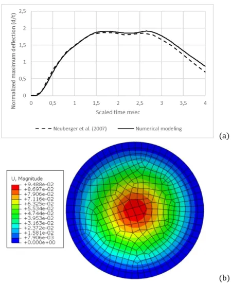
Young’s modulus, poison ratio and density of steel plate are considered to be 210 GPa, 0.28 and 7850 kg/m3
respectively. A bilinear plastic material model with isotropic hardening has been considered for the steel plate. Steel yield strength is taken to be 1000 MPa and plastic modulus is assumed equal to 2 GPa. According to the refer-ence informations, ultimate plastic strain is taken equal to 10%. The time history of plate mid point displacement has been compared with the reference results in Figure 3-a. The comparison shows that the selected procedure for numerical modeling has suitable reliability. In addition, the deformed shape of plate when the center point maxi-mum displacement occurs has been shown in Figure 3-b. This deformed shape is in a good agreement with steel plate deformation patterns that have obtained from tests in the reference.
(a)
(b)
6 INFILL STEEL PANEL MODELLING ASSUMPTIONS
As explained in section 3, in this application both in-plane and out-of-plane action are activated. Discussion about in-plane behavior is almost like the response of steel shear wall against earthquake. On the other hand, failure modes of in-plane action of steel panel against blast are the same as earthquake, except extra effects on material properties or structural dynamic response caused by impulsive loading. Review of previous researches clearly shows that the dynamic response of infill steel panel on impulsive loading depends on the plate width, height and thickness. Arraging the response to be in the required range with some modification should be applied onto plate by adding stiffeners. Infill panel behavior has a strong dependence on the arrangements and dimensions of stiffen-ers. Attaching stiffeners to bare plate causes change in internal forces, stress distribution and failure modes. A par-ametric study on infill panel components can give a good sense of achieving the proper design which satisfies re-quired performance, including both deformation minimization and energy absorption maximization. Therefore, it is required that a set of meaningful analyses be carried out with different panel geometrical assumptions to inves-tigate the in-plane and out-of-plane behavior of steel panels. An applicable descriptive conclusion from these anal-yses helps engineers make proper decisions on detailed design of infill steel panels. The geometry of models with different arrangements of stiffeners is represented in figure 4. As explained in section 3 of this paper, two vertical edges of panels are assumed to be free while the two horizontal edges are assumed to be restrained in three direc-tions, being able to rotate freely about the edge line. These boundary conditions are assumed for both in-plane and out-of-plane behavior.
Regarding nomenclature of the models in figure 4, the thickness of the steel plates and stiffeners in each case is equal; which means if the thickness of the steel plate is 5mm, the stiffener’s thickness will also be 5 mm. In this nomenclature, the number that follows P shows the thickness of the steel plate and stiffener in millimeters. If the model includes a stiffener, the letter S is used and the number of stiffeners is equal to the number that follows the letter S. The last number is the height of the stiffeners in millimeters. The dimensions of steel panels is assumed to be 3 m by 3 m and the vertical stiffeners are held equally spaced.
Figure 4: Different types of studied infill panels.
Shell element of type S4R in ABAQUS was used to model all the steel plates. S4R element is a four node doubly curved shell element, with reduced integration for instabilities prevention and large-strain formulation, which pro-vides a suitable tool for blast effect on steel plate modelling. The structured mesh was utilized to mesh the models. After performing sensitivity analyses, elements sizes were taken approximately equal to 0.06 m. The explicit anal-ysis was also used for the nonlinear dynamic analanal-ysis. As it has been explained in section 3, boundary conditions is assumed to be such that only displacements on top and bottom of infill plate are constrained in three directions. The rotations are assumed free. Also the stiffeners are assumed to be perfectly tied with plates.
7 STEEL PANEL OUT-OF-PLANE PERFORMANCE ASSESSMENT
7.1 Damage level of front steel panels against blast
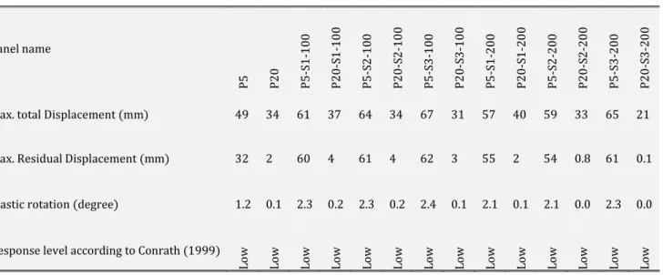
Maximum total deformation and maximum plastic residual deformation for all types of steel plate against low, medium and high intensity triangular impulse are represented below. Table 2 is related to 70 kPa- 20 msec impulse analyses results regardless of the maximum deformation location. The results show that as the plate and stiffener thickness increases, the differences between total deformation and residual deformation increases as well. It means that increasing the stiffness causes less ductility of panel in a given level of loading. Plastic rotations demonstrate that the response level is limited to low damage range according to definitions offered by Conrath (1999). It also is concluded that in this level of loading, A large portion of deformation for 5 mm thick steel panels is residual in different stiffener patterns. But 20 mm thick panel mostly acts in elastic range.
Table 2: Deformation response against triangular 70kPa- 20 msec impulse
Panel name
P5 P20 P5-S
1-10 0 P2 0-S1 -1 00 P5 -S 2-10 0 P2 0-S2 -1 00 P5 -S 3-10 0 P2 0-S3 -1 00 P5 -S 1-20 0 P2 0-S1 -2 00 P5 -S 2-20 0 P2 0-S2 -2 00 P5 -S 3-20 0 P2 0-S3 -2 00
Max. total Displacement (mm) 49 34 61 37 64 34 67 31 57 40 59 33 65 21
Max. Residual Displacement (mm) 32 2 60 4 61 4 62 3 55 2 54 0.8 61 0.1
Plastic rotation (degree) 1.2 0.1 2.3 0.2 2.3 0.2 2.4 0.1 2.1 0.1 2.1 0.0 2.3 0.0
Response level according to Conrath (1999)
Lo w Lo w Lo w Lo w Lo w Lo w Lo w Lo w Lo w Lo w Lo w Lo w Lo w Lo w
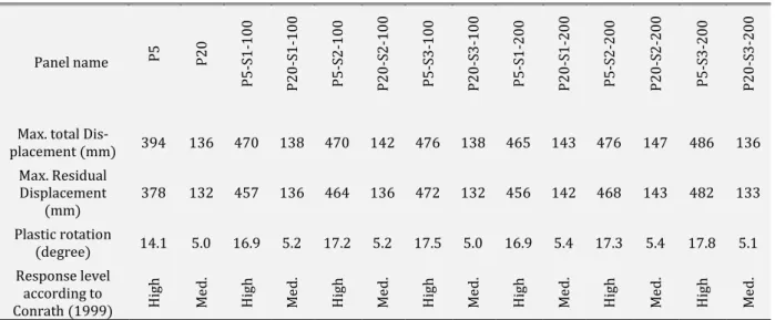
Another set of analyses is related to triangular impulse loading with reflected over-pressure of 350 kPa and the duration of 20 msec. It is obvious from table 3 that in this level of loading, even thicker panels show more ductility hence, the damage level of 5 mm thick panel increases to medium. However, about 20 mm thick panel damage is limited to low level category.
Table 3: Deformation response against triangular 350kPa- 20 msec impulse
Panel name
P5 P20 P5-S
1-10 0 P2 0-S1 -1 00 P5 -S 2-10 0 P2 0-S2 -1 00 P5 -S 3-10 0 P2 0-S3 -1 00 P5 -S 1-20 0 P2 0-S1 -2 00 P5 -S 2-20 0 P2 0-S2 -2 00 P5 -S 3-20 0 P2 0-S3 -2 00
Max. total Dis-placement
(mm) 252 68 248 74 255 77 261 75 256 83 261 76 273 71
Max. Residual Displacement
(mm) 242 64 245 67 249 66 258 63 246 63 254 61 272 56
Plastic
rota-tion (degree) 9.2 2.4 9.3 2.6 9.4 2.5 9.8 2.4 9.3 2.4 9.6 2.3 10.3 2.1 Response
level accord-ing to Conrath
(1999) Med
. Lo w M ed . Lo w M ed . Lo w M ed . Lo w M ed . Lo w M ed . Lo w M ed . Lo w
effect, both thicknesses reach a considerable residual deformation related to total deformation. Furthermore, the performance of 20 mm thick panel remains in medium damage range, whereas 5 mm thick panel exceeds high level of damage.
Table 4: Deformation response against triangular 700kPa- 20 msec impulse
Panel name P5 P20
P5 -S 1-10 0 P2 0-S1 -1 00 P5 -S 2-10 0 P2 0-S2 -1 00 P5 -S 3-10 0 P2 0-S3 -1 00 P5 -S 1-20 0 P2 0-S1 -2 00 P5 -S 2-20 0 P2 0-S2 -2 00 P5 -S 3-20 0 P2 0-S3 -2 00
Max. total
Dis-placement (mm) 394 136 470 138 470 142 476 138 465 143 476 147 486 136 Max. Residual
Displacement
(mm) 378 132 457 136 464 136 472 132 456 142 468 143 482 133 Plastic rotation
(degree) 14.1 5.0 16.9 5.2 17.2 5.2 17.5 5.0 16.9 5.4 17.3 5.4 17.8 5.1 Response level
according to Conrath (1999) Hig
h M ed . H ig h M ed . H ig h M ed . H ig h M ed . H ig h M ed . H ig h M ed . H ig h M ed .
Deformation contours in different stiffener arrangements for triangular 350kpa- 20 msec impulse are demon-strated in figure 5. It is clear that the maximum deformation belongs to the middle of vertical edges of panels.
Figure 5: Deformation contours for triangular 350kpa- 20 msec impulse.
increasing the numbers of stiffeners and stiffeners arrangement causes plate bending pattern to be changed, and due to changing the plate bending main direction, maximum displacement takes place on the panel edges. It is sug-gested to use edge stiffeners to remove this unexpected behavior. This solution improves the out-of-plane perfor-mance of the panel.
7.2 Transmitted impulse through infill panel
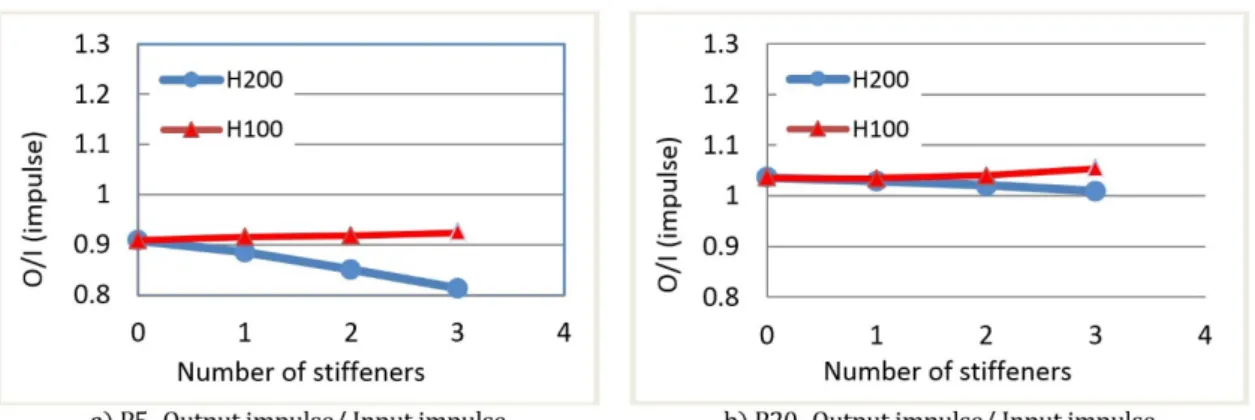
Figures 6, 7 and 8 represent the effect of panel stiffness on transmitted impulse to peripheral supports against triangular 70 kpa- 20 msec, 350 kpa- 20 msec and 700 kpa- 20 msec impulses, respectively. The integral of reaction forces in first peaks of force time history is considered as transmitted impulse. After that, the effect of oscillation of reaction forces around a constant amount is neglected. The analyses results are normalized for input excitation. Figure 6 is related to steel panels with 5 mm and 20 mm thickness and different arrangements of stiffeners against 70 kpa- 20 msec loading whose associated deformations have been denoted in table 2. According to results, a large portion of the panel area remains elastic. It can be seen that the ratio of output impulse to input impulse is greater than 1.0. Another point is that the thicker the plate is, the greater impulse it transmits. It has also been concluded that 100 mm height stiffeners do not have any considerable effect on improving the behavior of plates. However, increasing the stiffener height to 200 mm in 20 mm thick panel causes the transmitted impulse to reduce up to 20 percent in comparison to other cases while the output/input impulse ratio remains over 1.0.
Figure 6: Transmitted impulse ratio against triangular 70kpa- 20 msec impulse.
Increasing the impulse intensity by a factor of five shows that O/I impulse ratio decreases generally. This is because plasticity appears in more regions in steel panels. In 5 mm thick panel which is more ductile than 20 mm thick one in this level of loading, the O/I ratio decreases to below 1.0 whereas in 20 mm thick plate, O/I impulse ratio is still above 1.0.
This result agrees with the results of performance denoted in previous section. According to residual defor-mation amounts from table 3, 20 mm thick panel damage level is less than 5 mm thick one. Therefore, it is concluded that the deformation control and ductility criteria will not be achieved at the same time. Another result is that add-ing stiffeners generally leads to decrease in the O/I impulse ratio.
It is concluded that stiffening the panel by stiffeners acts differently from stiffening by thickness increasing. In other words, adding stiffener induces ductility.
From comparing H100 and H200 data series in Figure 7 it is obvious that stiffeners with 200 mm height show more efficient performance. This behavior may be due to change in main bending direction by using stiffer stiffeners and changing plastic point distribution pattern in the infill panel. In summary, it can be said that thinner panel with stiffer stiffeners acts more efficiently from ductility aspect.
Figure 7: Transmitted impulse ratio against triangular 350kpa- 20 msec impulse.
As depicted in Figure 8 in case of increasing loading intensity to 700 kpa- 20 msec impulse, regardless of thick-ness of plates and the number of stiffeners, the O/I impulse ratios about 0.9 are obtained.
Figure 8: Transmitted impulse ratio against triangular 700kpa- 20 msec impulse.
According to previous discussion, if it is assumed that the response is set to medium damage level and the ductility criterion is considered more than 10%, the input impulse for impulses 350 kpa-20 msec and 700 kpa- 20msec reduces. Therefore, it is recommended to use 5 mm thick panel 20 mm thick panel respectively.
7.3 Transmitted reaction through infill panel
Another important point in panel performance evaluation is the transmitted support reaction. Analysis results show that thicker plates exhibits less ductility in a significant level of loading. Utilizing stiffer stiffeners is more efficient for reducing the support reaction. In addition, increasing the number of effective stiffeners presents more ductile behavior and also causes more reduction of support reactions. These results are obtained from reviewing the Figures 9, 10 and 11.
Figure 10: Transmitted reaction ratio against triangular 350kpa- 20 msec impulse.
Figure 11: Transmitted reaction ratio against triangular 700kpa- 20 msec impulse.
8 STEEL PANEL IN-PLANE PERFORMANCE ASSESSMENT
In this section, the in-plane behavior is investigated for both loading of Monotonic and impulsive.
8.1 IN- PLANE BEHAVIOR AGAINST MONOTONIC LOADING
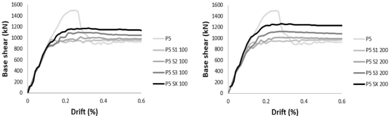
Monotonic analysis can offer a good view of the in-plane nonlinear behavior of panels. The base shear-drift diagrams, considering their plasticity coupled with the plate buckling, are represented in Figure 12 for different panel details. Occurring tension field after plate buckling makes the ultimate resistance of panel be more than what is desired. This increase in resistance is not stable since the geometry of plate and the buckling mode shape change due to continuing the monotonic loading and plate large deformation. Adding stiffeners also changes the buckling pattern. Increasing the number of vertical stiffeners removes the quick reduction of strength. Therefore, virtual unstable resistance increase will vanish and a more uniform structural behavior will be obtained. In fact, sudden resistance reduction is not a desirable performance. Figures 12 and 13 show the effect of stiffener adding on im-proving the excessive resistance and rapid drop in monotonic behavior for 5mm and 20 mm thick panels.
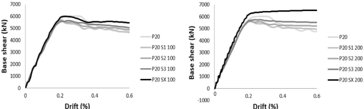
Figure 13: Effect of adding stiffeners on monotonic behavior of 20 mm thick panel.
Another obtained result is that using diagonal stiffeners can significantly increase the resistance and also the ductility of the infill steel panels. By investigating the models in this section and comparing the collected outputs from their analyses, it can be said that by increasing the steel plate thickness, the buckling arisen from the lateral drift is significantly controlled. Regarding the effect of the stiffener arrangement, it could be stated that in steel plates with lower thickness, the diagonal stiffener has a better effect on increasing the resistance and controlling the buckling. The effect of stiffeners arrangement on buckling pattern of 5 mm thick panel is shown in Figure 14.
Figure 14: Effect of stiffeners arrangement stiffness on buckling pattern of 5 mm thick panel in monotonic loading. Numerical results show that there is no considerable resistance degradation in monotonic loading, even in drifts more than 2.5%. The fact of capability of steel panels to bear the large story drift is reported in several cyclic tests (Astaneh-Asl 2001). Thus, using the stiffened panel as a shear wall in impulse application can act as a proper energy absorber, reserving an ideal stiffness.
8.2 IN- PLANE BEHAVIOR AGAINST IMPULSIVE LOADING
Figure 15: in-plane behavior against triangular 700kPa- 20 msec impulse on front wall.
On 20 mm thick panels, it can be seen that resonance happened after impulse duration time. In this case, stiff-eners height did not have any meaningful effect on residual deformation and free vibration period around residual in that situation. But it can be seen from Figure 16 that stiffener height has a significant influence on rapid dissipa-tion of after-shock vibradissipa-tion. It can be concluded that for 20 mm thick panel, three vertical stiffeners with 100 mm height have the best performance compared to other arrangements.
Figure 16: in-plane behavior against triangular 700kPa- 20 msec impulse on front wall.
A comparison of Figure 15 and Figure 16 shows that considering the performance level equal to life safety and the risk level equal to 700 kpa- 20 msec, 5 mm thick panel is preferred because of its ductility before total collapse. And yet, 20mm thick panels are not economic. Figure 17 shows the effect of stiffeners on tension field pattern which can influence in-plane ductility.
9 CONCLUSIONS
Out-of-plane and in-plane behavior of the steel infill panels against blast loading were studied in this article. The results show that the optimum design for out-of-plane behavior will be achieved when the transmitted impulse to the structural lateral bearing system is minimized. It is demonstrated that this goal is obtained by the selection of panel steel plate thickness and the stiffener arrangement such that the plastic points appear throughout the infill plate as much as possible. In opposite, stiffeners rigidity should be selected such that the average residual out-of-plane deformations remain in the range of accepted performance level. As a general rule for design beginning, it can be said that the reduction of in-fill plate thickness and increasing the number of effective stiffeners can improve the out-of-plane behavior regarding both criteria of energy dissipation and deformation control. About in-plane behavior, it is concluded that the effect of vertical stiffeners vanishes by decreasing the in-fill plate thickness. But in this case, X pattern stiffener can improve the strength and ductility of steel panel. Furthermore, analysis against monotonic loading shows that in-fill panels without any stiffeners have a proper strength regarding tension field effect but the drop down of strength due to buckling pattern changing in large deformation is not suitable. There-fore, in in-plane action it is preferred to using stiffeners even in vertical pattern, avoiding quick strength degrada-tion.
References
ASCE, (2011). Design of blast resistant buildings in petrochemical facilities, Petrochemical Committee, Task Com-mittee on Blast Resistant Design. New York, NY: American Society of Civil Engineers.
Asl, M. H., & Safarkhani, M. (2017). Seismic behavior of steel plate shear wall with reduced boundary beam section. Thin-Walled Structures, 116, 169-179.
Astaneh-Asl, A. (2001). Seismic behavior and design of steel shear walls.
Baker, W. E., Cox, P. A., Kulesz, J. J., Strehlow, R. A., & Westine, P. S. (2012). Explosion hazards and evaluation (Vol. 5). Elsevier.
Bjorhovde, R. (2004). Development and use of high performance steel. Journal of Constructional Steel Research, 60(3), 393-400.
Clough, R. W., & Penzien, J. (1993), Dynamics of structures, McGraw-Hill, New York.
Conrath, E. J. (Ed.). (1999). Structural design for physical security: State of the practice. American society of civil engineers.
DiPaolo, B. P., & Woodson, S. C. (2006). An overview of research at ERDC on steel stud exterior wall systems sub-jected to severe blast loading. In Structures congress 2006: structural engineering and public safety (pp. 1-10). Driver, R. G., & University of Alberta. Dept. of Civil and Environmental Engineering. (1997). Seismic behaviour of steel plate shear walls. (Doctoral dissertation, University of Alberta).
Dusenberry, D. O. (Ed.). (2010). Handbook for blast resistant design of buildings. John Wiley & Sons.
Elsanadedy, H. M., Almusallam, T. H., Alharbi, Y. R., Al-Salloum, Y. A., & Abbas, H. (2014). Progressive collapse po-tential of a typical steel building due to blast attacks. Journal of Constructional Steel Research, 101, 143-157. Jones, N. (2011). Structural impact, Cambridge university press.
Moghimi, H., & Driver, R. G. (2015). Performance assessment of steel plate shear walls under accidental blast loads. Journal of Constructional Steel Research, 106, 44-56.
Neuberger, A. Peles, S. and Rittel, D. (2007), “Scaling the response of circular plates subjected to large and close-range spherical explosions. Part I: Air-blast loading”, International Journal of Impact Engineering 34, 859– 873. Nguyen, T. P., & Tran, M. T. (2011). Response of vertical wall structures under blast loading by dynamic analysis, Procedia Engineering, 14, 3308-3316.
Salim, H., Dinan, R., & Townsend, P. T. (2005). Analysis and experimental evaluation of in-fill steel-stud wall systems under blast loading. Journal of structural engineering, 131(8), 1216-1225.
Simulia (2012). Abaqus Analysis User's Manual 6.12-3.
Smith, P. D., & Hetherington, J. G. (1994). Blast and ballistic loading of structures. Digital Press.
Stewart, L. K., Freidenberg, A., & Hegemier, G. (2014). Design and testing of a steel stud wall system for blast miti-gation. Structures Under Shock and Impact XIII, 141, 39.
Takahashi, Y., Takemoto, Y., Takeda, T., & Takagi, M. (1973). Experimental study on thin steel shear walls and par-ticular bracings under alternative horizontal load. In Preliminary Report, IABSE, Symp. On Resistance and Ultimate Deformability of Tsructures Acted on by Well-defined Repeated Loads, Lisbon, Portugal.
Tavakoli, H. R., & Kiakojouri, F. O. A. D. (2014). Numerical dynamic analysis of stiffened plates under blast loading. Latin American Journal of Solids and Structures, 11(2), 185-199.