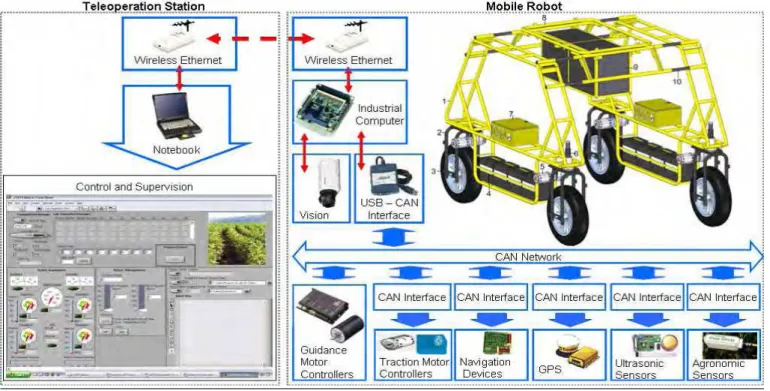
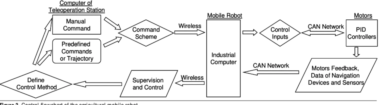
Design and implementation of an electronic architecture for an agricultural mobile robot
Texto
Imagem


Documentos relacionados
A "questão social" contemporânea, chamada erroneamente de "nova questão social", advém dessas profundas modificações nos padrões de produção, de
Porém, os dados específicos das humanidades, revelam um problema ainda maior, pois a diretriz que está posta no momento é a de extinguir o apoio financeiro federal à pesquisa
Os autores concluíram também que à medida que o nível de vida (medido pelo PIB per capita) aumenta, maior é o consumo e maior é a consciencialização dos
Ao longo do século XXI, a capital algarvia tem vindo a celebrar o le- gado dos seus poetas, através de eventos como “Faro Capital dos Poetas e da Poesia”, e a atribuição
12 momento, dividido em duas sessões, são apresentadas as interpretações dos atores entrevistados nesse trabalho, relacionadas à percepção do que é a Segurança e a
O objetivo deste trabalho consistiu no desenvolvimento e implementação de uma aplicação de registo de não conformidades – “NCR”, aprimorando assim, a estratégia utilizada pelo
Ou seja, a fotografia não como um documento de uma determinado rea- lidade, onde se autonomiza desse referente para se afirmar como uma possibilidade estética, mas a fotografia
He received the master’s degree in computers and electrical engineering from the University of Porto, Portugal, in 2014, presenting a thesis entitled Trajectory Planning of
