University Institute of Lisbon
Department of Information Science and Technology
MotionDesigner: A Tool for
Creating Interactive Performances
Using RGB-D Cameras
Filipe Miguel Simões Baptista
A Dissertation presented in partial fulfillment of the Requirements
for the Degree of
Master in Computer Science
Supervisor
Prof. Dr. Pedro Faria Lopes, Associate Professor
ISCTE-IUL
Co-Supervisor
Prof. Dr. Pedro Santana, Assistant Professor
ISCTE-IUL
"The art challenges the technology, and the technology inspires the art." [20]
Resumo
Desde há duas décadas que o uso da tecnologia em projetos artísticos tem proliferado cada vez mais, como é o caso das projeções interativas baseadas em movimento utilizadas em performances e instalações artísticas. No entanto, os artistas responsáveis pela criação destes trabalhos têm, tipicamente, de recorrer a especialistas em computadores para implementar este tipo de sistemas interativos. A ferramenta apresentada nesta dissertação, o MotionDesigner, pretende auxiliar o papel do criador artístico na conceção destes sistemas, permitindo que haja au-tonomia e eficiência no processo criativo das suas próprias obras. A ferramenta proposta possui um design orientado para estes utilizadores de modo a estimular e agilizar a criação autónoma deste tipo de obras e tem uma natureza extensível, na medida em que mais conteúdo pode ser adicionado no futuro. O software de-senvolvido foi testado com bailarinos, coreógrafos e arquitetos, revelando-se como uma ajuda e um catalisador do processo criativo da suas obras interativas.
Palavras-chave: Design, Interatividade, Tempo-real, Audiovisual, Projeção interativa, Câmaras de profundidade, Kinect, Arte, Multimédia, Performance, In-stalação.
Abstract
In the last two decades the use of technology in art projects has proliferated, as is the case of the interactive projections based on movement used in art perfor-mances and installations. However, the artists responsible for creating this work typically have to rely on computer experts to implement this type of interactive systems. The tool herein presented, MotionDesigner, intends to assist the role of the artistic creator in the design of these systems, allowing them to have autonomy and efficiency during the creative process of their own works. The proposed tool has a design oriented to these users so that it stimulates and proliferates their work, having an extensible nature, in the way that more content may be added further in the future. The developed software was tested with dancers, choreographers and architects, revealing itself as an aid and catalyst of the creative process.
Keywords: Design, Interactivity, Real-time, Audiovisual, Interactive projec-tion, Depth cameras, Kinect, Art, Multimedia, Performance, Installation.
Acknowledgements
I would like to acknowledge Prof. Dr. Pedro Faria Lopes for supervising this work and Prof. Dr. Pedro Santana for his careful supervision and constant aid in the development of this project. I also want to acknowledge all the dancers, chore-ographers, architects and multimedia artists interviewed during the development process, specially Beatriz Couto, Júlio Núncio, Maria Antunes and Catarina Júlio for their valuable feedback.
I direct a special acknowledgment to Maria Antunes, the dancer which collabo-rated in the creation of the small interactive dance performance we prepared using the developed tool, and to the Information Sciences, Technologies and Architec-ture Research Center (ISTAR) at ISCTE-IUL for the continuous support and for providing the necessary conditions to implement and test this project.
Contents
Resumo v
Abstract vii
Acknowledgements ix
List of Figures xiii
Abbreviations xv 1 Introduction 1 1.1 Context . . . 1 1.2 Motivation . . . 2 1.3 Research Questions . . . 5 1.4 Objectives . . . 6 1.5 Research Method . . . 7 1.6 Document Structure . . . 8 2 Literature Survey 9 2.1 Depth-Cameras Based Systems . . . 10
2.2 Interactive Projections . . . 10
2.2.1 Graphical Interactivity . . . 11
2.2.2 Sound Interactivity . . . 12
2.3 Tools for Creating Interactive Audiovisual Art . . . 14
3 System Overview 19 3.1 User Interface . . . 19 3.2 Hardware Setup . . . 22 3.2.1 Kinect sensor . . . 23 3.3 Software Setup . . . 25 3.3.1 openFrameworks . . . 26
3.3.2 OpenNI & NiTE middleware . . . 27
3.3.3 openFrameworks Add-ons . . . 27
4 Development and Implementation 29 4.1 Editing Studio . . . 30
Contents
4.1.1 Scenes Parameterizations . . . 33
4.1.2 Previewing the Projection Sequence . . . 36
4.1.3 Displaying the Scenes . . . 37
4.1.4 Projecting the Sequence . . . 39
4.2 Interactive Graphical Scenes . . . 41
4.2.1 Scenes Editing GUI . . . 42
4.2.2 Motion Capture Algorithms . . . 49
4.2.3 Particle System . . . 50
4.2.4 Drawing With Joints . . . 58
4.3 Interactive Audio . . . 62
5 Evaluation and Discussion 67 5.1 Evaluation Method . . . 67
5.2 Results . . . 70
6 Conclusions and Future Work 83 6.1 Conclusions . . . 83
6.2 Future Work . . . 85
Appendices 89 A GUI Design Sketches 89 A.1 Editing Studio . . . 89
A.2 Interactive Scenes . . . 90
B Source Code Snippets 91 B.1 Interactive Scenes GUI . . . 91
B.2 NiTE . . . 94
B.3 Particle System . . . 95
B.4 Joints Draw . . . 99
Bibliography 101
List of Figures
1.1 Pixel Performance . . . 3
1.2 Mind the Dots Performance . . . 3
2.1 Interactive Projection Setup Scheme . . . 10
2.2 Divided By Zero Performance . . . 11
2.3 MotionDraw’s User Interface . . . 15
3.1 System Setup . . . 20
3.2 MotionDesigner’s Editing Studio GUI Layout . . . 21
3.3 MotionDesigner’s Interactive Scene GUI Layout . . . 22
3.4 Kinect Sensor Hardware . . . 24
3.5 Kinect Sensor Inner Structure . . . 24
4.1 MotionDesigner’s Software Architecture . . . 30
4.2 Editing Studio’s Timeline . . . 31
4.3 Scenes Palette GUI . . . 32
4.4 Editing Studio’s Timeline Object . . . 33
4.5 Timeline Objects Parameterization Diagram . . . 34
4.6 Editing Studio’s Parameterizations Panel . . . 35
4.7 Editing Studio’s Preview Player . . . 37
4.8 Editing Studio’s Explore Button . . . 38
4.9 Copy/Paste Parameterizations Data Flow . . . 39
4.10 Editing Studio’s Panels Distribution . . . 40
4.11 Second Window for Projection . . . 41
4.12 Interactive Graphical Scenes GUI . . . 42
4.13 Parameters Panel Iterations . . . 43
4.14 Color Picker . . . 45
4.15 Color Picker Experimentations . . . 46
4.16 Interactive Scenes Editing GUI (using ofxUI ) . . . 47
4.17 Joints Selector Panel . . . 47
4.18 Particle System GUI with Joints Selector . . . 48
4.19 Particle System Example . . . 51
4.20 OF Functions Diagram . . . 53
4.21 Particle System Parameters . . . 54
4.22 Particles Color Interpolation . . . 55
List of Figures
4.24 Particle System Kinect Screenshot . . . 59
4.25 Joints Draw GUI . . . 60
4.26 Joints Draw Kinect Screenshot . . . 61
4.27 Explore Audio Button . . . 63
4.28 Interactive Audio Scene GUI . . . 64
4.29 MotionDesigner Logo . . . 66
4.30 Sketch and Final Implementation Comparison . . . 66
5.1 Users Implementation Suggestions Graph . . . 72
5.2 Evaluation Question 1 Graph . . . 73
5.3 Evaluation Question 3 Graph . . . 74
5.4 Evaluation Question 4 Graph . . . 75
5.5 Evaluation Question 5 Graph . . . 76
5.6 Evaluation Question 8 Graph . . . 79
5.7 Evaluation Question 9 Graph . . . 79
5.8 Interactive Performance Rehearsal (Performer) . . . 81
5.9 Interactive Performance Rehearsal (User) . . . 81
Abbreviations
OF OpenFrameworks
IDE Integrated Development Enviroment GUI Graphical User Interface
Mocap Motion Capture OSC Open Sound Control SDK Software Development Kit FBO Frame Buffer Object
XML eXtensible Markup Language FPS Frames Per Second
Chapter 1
Introduction
1.1
Context
Since the 1950s a lot of artists and computer scientists started to use programming to create different art pieces and this is a practice that continues today thanks to an enthusiast group of creative programmers all around the world [3]. Nowadays the community of artists and programmers that create computer art is bigger than ever. It was in the 90s that the use of technology in contemporary art increased exponentially and a lot of interactive systems started to be developed as result of a collaboration between computer programmers/software engineers and artists from different fields like painting, dancing and cinema [36]. The term coined to describe what these programmers and engineers were doing is creative coding.
Creative coding is a term that was coined to distinguish a particular type of programming in which the developer pretends to create something expressive. It is used to create live audiovisuals, interactive projections for art performances or installations, interactive soundscapes, etc [4]. Programming such systems helps artists to lately produce real interesting works, but it represents a real challenge to programmers and software engineers.
Chapter 1. Introduction
Today there are many different tools and libraries that help programmers and engineers to prototype and develop interactive systems to embed in art perfor-mances or installations. Many of these libraries can be used within different toolk-its. The most popular toolkits used nowadays by creative coders are openFrame-works (OF), Processing, Cinder, Max/MSP, etc [9] [12] [1] [5]. By integrating one of these toolkits and their libraries within a chosen Integrated Development Environment (IDE), like Microsoft Visual Studio for instance, a lot of possibilities can be explored and implemented in a much more prolific way.
Despite having many tools that support the implementation of interactive au-diovisuals generated by the computer and affected by another person (through the use of a video camera, for instance [24]) there are not many tools, already imple-mented, that help the creative people to produce these interactive works without having to program them or without depending on the technical knowledge of an-other person.
1.2
Motivation
Despite the challenge of creating interactive systems for an art performance or installation, many programmers and engineers collaborated with different artists to produce them over the past years. Today there are many art works based on the interaction between a person, typically an art performer, and a computer sys-tem [26] [11] [24]. Two of the most explored types of human-machine interaction in an artistic work are installation art and interactive performance, where spe-cial cameras, called RGB-Depth cameras (or simply depth-cameras), are used to capture the position and movement of the user/performer, allowing him/her to directly interact with the art piece.
Figures 1.1 and 1.2 show two different art performances which used interac-tive computer systems, both capable of producing computer graphics that would be manipulated by a dancer or performer. In both of these systems, the body movement data was captured by RGB-Depth cameras.
Chapter 1. Introduction
Figure 1.1: “Pixel”, a dance piece where the graphics projected on the wall and floor are transformed by the dancers position and movement [11].
Figure 1.2: “Mind the Dots” a piece where a solo dancer interacts with virtual dots creating abstract graphic shapes generated by a computer [7].
Interactive systems like those used on the shows pictured on Figures 1.1 and 1.2 are complicated to implement, not because a special hardware is needed (in these cases only a depth-camera connected to the computer and calibrated correctly), but mainly because of the programming complexity behind such systems. To sur-pass this challenge the artists often collaborate with skilled programmers and soft-ware engineers to implement the system they want for a specific art piece. However, despite the interesting aspects of having different people from different work fields
Chapter 1. Introduction
collaborating with each other, the fact that they need to interact so intricately can be seen less positively, since it often works as an undesired inter-dependency, typically for the creative person. Due to this dependency issue, the creative peo-ple also need a tool to help them create these type of works autonomously. Such dependency questions arise because the creative process behind any work needs the ideas and their concretion to be a quick and fluid action-reaction process.
Having the artists dependent of computer programmers to successfully imple-ment their own ideas for an interactive system will make the creative process longer and not as fluid as should be. This happens because the artists need the imple-mentation of their ideas to be completed and presented to them in order to know if it feels right and give feedback to the programmer. Therefore, the action-reaction process behind any creative work is impaired by this inter-dependency between artist and programmer.
Through early interviews with the target audience, we found that the artists also like to have real-time control over the projection content and over how the use of the technology is explored during the performance, which sets the basis for any improvisational work. Although the artists can show their work in the presence of a programmer or other computer operator, they can not immediately and autonomously perform those changes without depending on the programmer’s knowledge [35].
In order to fight the dependency problem that artists often have to face, and to allow them to autonomously explore the creative possibilities in a more comfortable and effortless way, there should be a tool oriented for these people. It would be through this tool that they would be able to manipulate and conduct the content of the projection they are creating and specify the rules of interaction between the performer/viewer and the content created, in an intuitive way.
Having a tool that aids the creation of interactive projections the artists can create interactive installations or performances without (necessarily) depending on the technical skills of a computer programmer. This will, hopefully, allow the creative people to quickly see results during the implementation of their ideas 4
Chapter 1. Introduction
since, through the interaction with a simple and intuitive Graphical User Interface (GUI), they can quickly and intuitively manipulate the audiovisual content of the piece and explore the combination of rules by which the content plays in relation to the viewer or the performer without needing to write code.
Developing a tool for the creation of interactive projections that serve a cre-ative purpose, will be beneficial for artists like choreographers, performers, theater directors, etc., since they can have a tool that will possibly serve their needs for producing interactive digital art in a comfortable and autonomous way. But many different people can also benefit from such tool even if they are not artists. People like researchers and professionals working with human-machine interaction can benefit from the creation of such system, as well as architects. The latter can, for instance, use a tool like this to create a media wall for a building or use it to create an interactive art piece for a museum or other space found pertinent.
The tool herein proposed, MotionDesigner, is a computer program with which the creative people can autonomously create an interactive projection and ma-nipulate its audiovisual content and relate it with data gathered from the body movement of a third-person (performer, person from the audience, etc.). The in-teraction between the performer and the projection content is done through the use of an RGB-D camera. This tool will hopefully boost the creative process of such interactive art works, since now the art creator can autonomously and immediately test out the different possibilities for the projection content.
1.3
Research Questions
Facing the fact that artists often need to depend on a computer programmer to im-plement the interactive systems to use in their art works, the tool herein presented was developed with the goal of answering the following research questions:
1. Can a computer program oriented for the creative people give them the sufficient autonomy to create their own interactive projections?
Chapter 1. Introduction
2. Is it possible for the artists to feel they have control over the projection con-tent and the interaction rules between the digital work and the performance?
These questions were a conductive force in the software development, in order to produce a more intuitive system and to better understand what are the elements the software must provide the users so they can create a set of graphical scenes to be projected, create an interactive soundscape and set the rules of interaction between the body of another person and the projection according to their own needs.
1.4
Objectives
In order to know if a single computer program can help artists to autonomously create their interactive projections, the main objective of this work is to elaborate and develop a standalone software to be used by choreographers, theater directors, performers, architects or anyone who wants to create an interactive performance or art piece by manipulating audiovisual content in real-time through motion capture, and facilitate the creative process of such works.
Using some affordable hardware (a depth-camera like Microsoft Kinect) the software should provide all the means to create, edit and sequence audiovisual content for a projection, allowing the user to create a sequence of different 2D/3D graphical scenes (with computer graphics created in real-time) and set, if wanted, an interactive soundscape using the desired sound samples. The software should also allow the user to specify how the person being detected by the depth sensor will affect the projected graphical scenes and/or the sounds being played, by choosing witch body joints participate in the interaction, as well as adjust the parameters that dictate how the graphical information is represented.
By giving control over the projection content, the tool herein proposed pretends that its users autonomously integrate the elements they need, without having to depend on programming skills or other technical dependencies, by making the
Chapter 1. Introduction
generation, transformation and sequencing of audiovisual content manageable by the user through an intuitive and simple interface. This is how the proposed tool aims to help the creative people, like artists and architects, to develop their work independently and productively.
1.5
Research Method
During the development process the Design Science Research method was used [37], which is a process with different models of approach for solving problems and is divided in the following steps:
1. Problem identification and motivation
2. Objectives of a solution
3. Design and development
4. Demonstration
5. Evaluation
6. Communication
The first step of this process resulted in what is explained in Sections 1.1 and 1.2 of this chapter, since they explain the artists’ need for having a tool like the one herein proposed. The second step is covered in Section 1.4, which describes which kind of solution we are going to implement. The third and fourth steps will be described in Chapters 3 and 4, which explain each feature of the proposed solution and describe its development process, respectively. Lately, in Chapter 5 the evaluation process and its results will be presented.
Chapter 1. Introduction
1.6
Document Structure
This document describes all the aspects of our project, from the proposed system’s premises to its implementation and evaluation processes, having the following structure:
• Chapter 2 overviews some of the existing projects in interactive performance using RGB-D cameras and the tools that aid the artists in the creation of such works, comparing them with our approach.
• Chapter 3 gives an overview of the proposed system, describing its principles, features and design and introduces the hardware and software tools we chose to implement this system.
• Chapter 4 describes the implementation of the proposed system, explaining how each feature was implemented and how they are presented to the final user.
• Chapter 5 describes the evaluation method chosen to validate our work and the results of these evaluation tests with the final users.
• Chapter 6 presents the final conclusions of our work and proposes a number of features that can be implemented in the future
Chapter 2
Literature Survey
Creating interactive systems using motion capture data is a practice that resulted in many different applications until today, specially in artistic mediums. From all these different applications, a great majority are in the context of interactive projections for a dance performance or installation. Typically what these systems have is a sequence of computer graphics projected on a surface, like a wall or the floor [11] [24] [26], and/or an interactive soundscape to set the mood of the performative work [18]. This area of interactive art performance and installation art is one of the most creative areas explored until today regarding the marriage between arts and technology.
Researchers like O’Neal, Meador and Kurt worked with dancers using motion capture (mocap) suits in order to generate computer data by their movement and input this data into an interactive system [30] [31]. Other researchers like Latulipe and Huskey [29] used instead a portable mice, while Hewison, Bailey and Turner [16] used vision sensors that they integrated with the performers’ suits. Some years after these projects have appeared, the mocap process started to be made using external markers attached to the performers’ bodies [21]. The main limitations associated with all these different motion capture techniques are the occlusion of markers or sensors and the movement limitations that arise by the use of special suits and the gear attached to it.
Chapter 2. Literature Survey
2.1
Depth-Cameras Based Systems
The appearance of RGB-D cameras, or depth cameras, opened a new space of opportunity for multimedia computing, allowing the implementation of motion-capture-based systems without the need of special apparel or hardware apart from the cameras/sensors themselves [38]. Many researchers started to work with these depth sensors in order to fight the problems of marker occlusions and movement limitations [26] [11] [24], making the mocap process more comfortable and produc-tive.
2.2
Interactive Projections
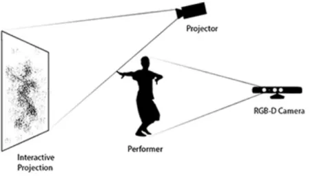
The possibility of having a simple camera capturing all the movement data from a person without the need of special apparel caused the arise of interactive art pieces where a person, or more, can stand in front of the sensor and instantly and comfortably interact with the audiovisuals being computed. The visual result of this interaction is often projected on a plane surface like a wall or the floor. In Figure 2.1 it is shown the setup we typically find in an interactive work like this (e.g., [24] [35]).
Figure 2.1: Typical setup for an interactive projection using RGB-D cameras.
Chapter 2. Literature Survey
2.2.1
Graphical Interactivity
An example of a work that uses depth-sensors to capture the movement data of a person, in this case a dancer, is an interactive performance called .cyclic., which combines computer graphics with dancing and Kinect technology [26]. In .cyclic. a pre-sequenced set of images to be iterated are synced with the music and drawn to the screen according to the performer’s position.
There are other projects that had a similar approach to .cyclic., providing computer generated graphics manipulated by the performer in real-time, using a depth camera. An example is the project Divided By Zero by Hellicar and Lewis [24], which resulted in an interactive dance performance that used depth sensor technology to track the dancer’s body silhouette which would affect the visuals that were generated in response, in real-time. In this project, no pre-rendered video was used and the soundscape used was not generated or affected in real-time, but rather was something pre-recorded. See Figure 2.2 to have an idea of the visual aesthetic of this performance.
Figure 2.2: An abstract representation of the dancer’s silhouette is pro-jected on a wall and transformed by her movement in real-time, so as in
Hel-licar&Lewis’s Divided By Zero, 2010.
Another project that focuses on the interaction between projected graphics and a performer using depth sensors technology is one of Benjamin Glover[22]. In
Chapter 2. Literature Survey
this project, Glover developed an interactive system using openFrameworks (OF) libraries and a Kinect sensor to interact in real-time with computer graphics pro-jected on a wall. The system developed by Glover allowed the configuration of the visual aspect of the projection to be changed in real-time through the interaction with a simple GUI [22], but the order of the elements that would be projected was pre-programed and not easily changeable. The system also did not cover any as-pect of interactive sound in real-time. Despite the graphical interactivity of these systems, none of them focuses on sound manipulation in real-time. However, some researchers already explored the possibility of having the performer’s movement interact with both the graphical elements and the soundscape of the art piece.
2.2.2
Sound Interactivity
A research project that marries interactive sound with graphical elements is the one by Joey Bargsten, in which he developed two interactive applications using PureData and Quartz Composer software to control audio and graphical content, respectively, using a Kinect sensor [17]. To extract the data to input in both PureData and Quartz Composer he used a software called Synapse along with some Open Sound Control (OSC) routers [17]. He concludes that OSC controllers with Kinect technology can bring new opportunities in translating the motion of the human body to transformations in both sound and images. However, Bargsten defended the division of labors and focused on the advantages of exploring sound and video in their separate domains. Despite this, Bargsten’s article addresses the possibility of having a system that displays interactive sound and graphics simultaneously and in real-time. Ultimately, no software capable of doing both of these things was actually implemented.
There is another project, by Berg et al. [18], in which sound interactivity is the main focus. In this project the researchers produced a music generator system where each joint of the mover was responsible to transform a specific sound sample. In this system, no graphical interaction was developed, but the generation and
Chapter 2. Literature Survey
manipulation of different sound samples through the movement of a person’s body was a considerable advance in this research area.
By analyzing all these different projects we conclude that, to the best of our knowledge, there is a scarcity of systems that provide the possibility to interact with both the computer-generated graphics and the sound used in the performance or installation. This scenario of having a person not only conducting the behavior of the projection elements but also being the conductor of the soundscape is some-thing yet to be explored. A commom issue among all these projects is that the use of more than one RGB-D camera for the mocap process is never referred. The reason for not having these interactive systems using more than one depth camera may be the fact that this represents a big technological challenge, since problems like the unreadability of the point clouds generated by the Kinects may arise (due to the infrared mapping overlap), which makes the data partially unreadable and much more difficult to deal in terms of programing and calibration of the sensors. The system herein proposed was implemented using only one RGB-D camera due to these reasons.
Taking into account the state of the art regarding the use of technology in art performances and installations, from the most suitable hardware to the solutions implemented, one can conclude that the implementation of such systems could be richer if they provided both audio and visual control and if the creative person could have the control of these elements, since lot of interesting possibilities could be fulfilled by their artistic vision.
As depicted in the literature review, the artists or architects interested in creating an interactive projection to integrate in their art work, often do it by asking a programmer or a software developer to implement the solution they need for that specific work [26] [23]. What happens in these situations is that the artists depend on the programmer or engineer productivity to see the results implemented, i.e., they need to wait for the implementation to be completed in order to test it. Only then the artist can continue the creative process by refining that idea and thinking about new ones. This is a problem the artists often find during
Chapter 2. Literature Survey
the creative process of these type of works. Additionally, the solution typically implemented are a sequence of code lines that run during the exhibition of the art piece and have a preset order of events, i.e., there is no possibility for the creator of the art piece to change the order of what is being projected in real-time.
2.3
Tools for Creating Interactive Audiovisual Art
Facing the autonomy problem that the creative people typically have during the creative process of interactive art works that embed technology, there should be a tool that aids them by allowing them to:
1. Choose their own projection content without needing to program them;
2. Change the aspect of the projection content and the interaction rules between the performer and the projection and/or the soundscape, in real-time;
3. Freely sequence the order of the interactive content he/she is using in the projection, i.e., what is seen/heard during the performance/exhibition and when.
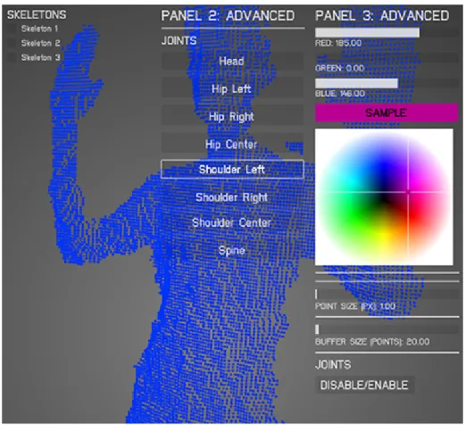
One of the few examples of artists-oriented tools for creating interactive per-formances/installations is a tool called MotionDraw [35], implemented using OF libraries, which focuses on enhancing the experience of the artist when conducting an interactive projection in real-time. In this work only the graphical interac-tivity is considered, i.e., no sound interacinterac-tivity is explored, but they explore the graphical interaction in a different way than the works discussed previously by creating a tool oriented for the artist. In MotionDraw, the creative person can directly manipulate the visual aspect of the projection - which conceptually is something similar to brushes painting on a canvas - by interacting with a simple GUI that allows him/her to configure the aspect of the brush for each body joint being captured by the Kinect sensor and choose which joints are active (2). This system’s interface, depicted in Figure 2.3, allows the artist to freely explore the
Chapter 2. Literature Survey
possible visual representations of the scene in real-time. However, this tool does not give the user freedom to choose another content for the projection apart from the drawing brushes. So, this is a tool for a one-case scenario and lacks on other types of interactive scenes for the users to work with and an environment where they can sequence the projection content and use them as they want.
Figure 2.3: MotionDraw’s simple GUI allows the user to control the aspect of each joint’s brush in real-time.
Another example of a tool that was developed for the artists to directly ma-nipulate the projection content by interacting with a simple and intuitive GUI is Adrien Monodot and Claire Bardainne’s eMotion [15], which is a software de-veloped for displaying virtual objects chosen by the user (1) and make the body motion of a performer, which is being captured by a depth sensor, to interact with those virtual objects. The user of the software can easily change the behavior and representation of the virtual objects by manipulating the physics laws governing those objects, through the interaction with a simple GUI (2). However, this tool is also a one-case scenario, meaning that the users do not have much freedom to
Chapter 2. Literature Survey
choose which elements are represented on the scene nor sequence them as they want.
In the case of MotionDraw the user can set the aspect of the projection in real-time by manipulating the color of the scene elements and the width of the trail left by the joints, as well as choose which joints are visible, which verifies the second feature of the three previously proposed. In eMotion the users have more freedom to choose which elements are shown by choosing which type of 3D graphics are shown in the projection, however they can not choose and sequence a set of different types of graphics to be projected, so it is not a considerable freedom for the user in terms of control. This, however, can validate both the first and the second conditions in the case of eMotion.
In both the MotionDraw [35] and eMotion [15] cases the user of the software, typically the artist responsible for envisioning the interactive projection, does not have more than one type of graphical scene to use in the projection and, conse-quently, can not sequence multiple types of scenes to project (3). In both these cases the artist also can not use interactive sound within the provided tools, which means that if they want an interactive soundscape to go along with the projection they need to implement it (or ask for that implementation) outside the environ-ment of the provided tool. This makes none of the tools we know at the moenviron-ment eligible for the third feature, i.e., allowing the users to freely sequence the order of the interactive content they want to project.
At this point, one can see that the number of tools available for the creative people to make and conduct their own interactive performances or installations is small and that, even those that already exist, do not give the user freedom to choose different types of interactive content to be projected and sequence them along the exhibition time. If the users wants to mix different types of interactive graphics in their interactive projection they can not do it autonomously, since they need a programmer to implement other scenarios. Having he ability to use more than one type of interactive scenes in the projection and, for each of them, having the freedom to parameterize it and configure its interaction rules is something we
Chapter 2. Literature Survey
will cover in the system herein proposed, as well as the ability for the user to create an interactive soundscape to go with the projection.
In order to fill the gap on the existing tools that intend to aid the artists, and to fulfill all the three features proposed, the tool herein presented, MotionDesigner, provides the users an environment where they can set which type of graphical and audio elements are going to be projected during the interactive performance or installation and also when, i.e., the users can sequence the audiovisual elements along the projection time, as well as change their aspect and behavior in real-time. This makes the proposed tool fulfill all the three aspects that shall aid the users in creating an interactive projection.
Chapter 3
System Overview
In order to cover the gap that exists in the supporting tools for the artists to create their own interactive projections based on the capture of human body movements, we propose a software tool that focuses mainly on the creative person responsible for the artistic ideas behind the interactive work. In the system herein proposed, the creative person is the final user of the software and will act as the conductor of the projection itself, from dictating which content is being presented in the projection to setting the rules of interaction between the performer’s body and the audiovisual elements of the performance.
3.1
User Interface
The system presented in this dissertation is composed of a software we developed, which we called MotionDesigner, and an RGB-D camera, like Microsoft Kinect, as seen on Figure 3.1. The RGB-D camera captures all the movement from the performer’s body and feeds it into the software, which computed the graphical and audio data according to the body pose. A projector connected to the computer projects the resulting visuals in a plain surface. The developed software and is to be used by anyone who wants to create an interactive projection using real-time computer-graphics and sound manipulation through the movement of a human
Chapter 3. System Overview
body. It is by directly interacting with the software that the users can to change the aspect and behavior of the projection.
Figure 3.1: The system herein proposed is composed by a software, Motion-Designer, an RGB-D camera, which captures the body movement of at least one
person, and a projector that maps the resulting visuals in a plain surface.
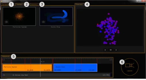
The software to be used by the creative person who pretends to create an interactive projection, MotionDesigner, has a simple and intuitive Graphical User Interface (GUI). It is by interacting with this GUI that the creator of the projection can choose what to display on the projection (which graphical elements), what is their visual aspect (which can be set before projecting the graphical content or during the live projection) and when these graphical elements, as well as the sounds the user wants to play, will appear during the projection. Figure 3.2 shows the main interface of MotionDesigner, which is called Editing Studio.
The Editing Studio is the first environment to be presented to the users, and it has a timeline-based interface. In this environment the users can drag to a timeline a set of graphical scenes to be projected and sounds samples to play along with the projection. The panel with the graphical scenes and the panel with the audio files are displayed according to the tab currently selected by the user (in Figure 3.2 the scenes palette is the panel currently selected). It is on this timeline where the users can manipulate the projection time of each audiovisual element and set their order of appearance. These are all concepts borrowed from video editing systems.
Besides sequencing the audiovisual elements and set their duration, the user is also be able to set timestamps/markers during the projection time of a scene 20
Chapter 3. System Overview
Figure 3.2: 1 - Parameterizations Panel, where the user can add times-tamps to a scene form the timeline and set the desired parameters for that time instant; 2 - Scenes Palette, which displays the graphical scenes the user can drag to the timeline; 3 - Sounds Palette, which displays the sound samples the user can drag to the timeline; 4 - Preview Player, where the user can preview the scenes representation over time according to the current parameterizations; 5 - Timeline, where the user can sequence the graphical scenes and set their duration; 6 - Launch Button, where the user can play/launch the sequence
onto the projector.
(represented by the red lines on the timeline) and associate to them a set of values for that scene’s parameters. This allows the user to pre-parameterize the scene without having to change the scene visual aspect only in real-time, i.e., only when the scene is being projected. This feature is provided because, although the real-time live manipulation is one of the core principles of the proposed system, it is also interesting to allow other scenarios where the users already know what they want to project and how.
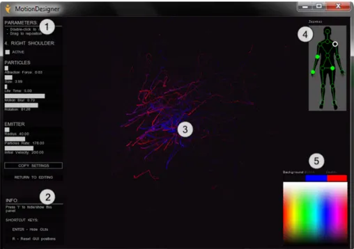
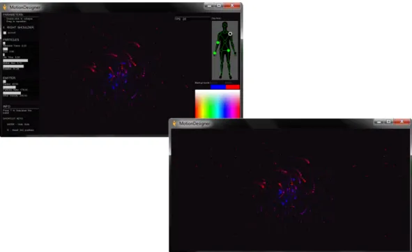
The users also need an interface to freely parameterize an interactive scene, i.e., a GUI that allows them to experiment different possible representations for a specific scene. Figure 3.3 shows the interactive scenes editing GUI. This inter-face is presented to the users whenever they press the Explore button, which is represented in Figure 3.2 as an eye icon on the bottom left corner of each scene from the scenes palette. When the users press this button the respective scene is launched in fullscreen along with this GUI, so that they experiment with that scene before the live projection. When the timeline sequence is projected during
Chapter 3. System Overview
the live performance the users can see the current scene content replicated on the computer screen along with this editing GUI, which allows live parameterizations in real-time.
Figure 3.3: 1 - Parameters Control Panel, sliders-based panel where the user can set a different value for each scene parameter; 2 - Info Panel, panel with useful info, namely short key commands; 3 - Scene Content, where the scene is displayed as is being rendered on the projection; 4 - Joints Selector Panel, where the user can choose which of the performer’s body joint is going to be parameterized (how much that joint affects the projection); 5 - Color
Picker, where the user sets the color for each scene element
Whether the users are live projecting the audiovisuals sequence or simply ex-perimenting different parameterizations for a specific scene, they are presented with the interface depicted in Figure 3.3. The content of the scene depends on the type of scene that is being previewed or launched.
3.2
Hardware Setup
Since the audiovisuals used in the projection focus on the interactivity with body movement, a technology to successfully recognize the human body and provide
Chapter 3. System Overview
that information as usable data to be computed by the software is needed. Mo-tionDesigner is prepared to be used with an RGB-D camera, which is responsible for capturing point clouds of the scene. These point clouds data are processed by a third-party software, namely, NiTE, to infer the pose of the performer’s body.
In order for the proposed system to be easily usable and accessible to the majority of the target audience, we needed to integrate a reasonably accessible depth camera. Microsoft Kinect was seen as the most appropriate camera since it provides all the necessary technology by a considerably low monetary cost.
3.2.1
Kinect sensor
Kinect is a consumer-grade range camera, or depth camera, created by Microsoft in 2010 [34]. It was initially designed with the purpose to commercialize it along with Xbox 360 so that the users of this console could physically interact with the game and control them through their body movements [6]. However, since its release, many people started to explore its application in different domains [27].
Like any other RGB-D camera, the Kinect has an RGB camera and a 3D depth sensor. As depicted in Figure 3.4, it also has a multi-array microphone (composed of four microphones) for sound capture and a 3-axis accelerometer, from which is possible to infer the current orientation of the camera [38]. The RGB camera has a resolution of 1280x960 and it can be used to capture a colored image or to stream video [22]. The depth sensors are composed of an infrared projector and an infrared camera (see Figure 3.5). The first emits a dot pattern of infrared light onto the scene and the other receives the reflected beams of the pattern and infers the depth information from the deformations imposed by the geometry of the scene to the projected dots [38].
After the release of Microsoft Kinect for the Xbox console, Microsoft an-nounced, on February 21, 2011, the release of Kinect for Windows. This is the same device already released for the console but usable and programmable on the
Chapter 3. System Overview
Figure 3.4: Microsoft Kinect hardware composition
Figure 3.5: Inner structure of the Microsoft Kinect sensors
computer. They released the device in the same year, with a non-commercial Software Development Kit (SDK) associated to it [32].
Soon after the release of Kinect for Windows, a lot of people started to program different type of systems, exploring the creative possibilities behind the applica-tion of this technology. Since its release a lot of artists already integrated the Kinect in their artistic works, specifically in interactive dance performances and art installations [24] [26] [11].
Chapter 3. System Overview
3.3
Software Setup
Since the Kinect sensor is being used to capture the body movement data to input into our system, the choice of the programming environment and the libraries used to manipulate this data was done carefully. Currently there are two strong can-didates for the programming libraries to be used to develop the proposed system, being those:
Kinect SDK Released from Microsoft along with Kinect for Windows [2] Programming Languages: C++, C#, Visual Basic or other .NET language
openFrameworks An open source toolkit designed to assist creative coding [9] Programming Language: C++
Table 3.1 presents the main characteristics of both options side-by-side. This comparison allowed us to understand what was the most appropriate choice for the project implementation.
openFrameworks vs Kinect SDK
openFrameworks Kinect SDK
Open-source and cross-platform Not open-source nor cross-platform Commercial usage Commercial applications not allowed Skeletal and Hand Tracking Skeletal and Hand Tracking
Oriented for sound sampling control Sound sampling control is possible
Oriented for computer graphics gener-ation
Computer graphics generation is possi-ble
Table 3.1: Comparison between openFrameworks and Kinect SDK features
Choosing between Kinect SDK and openFrameworks simply regarding the mo-tion tracking capabilities is something that should suit the developer preferences, since both can do it. However, there are several reasons that highlighted open-Frameworks over Kinect SDK. As Table 3.1 shows, openopen-Frameworks, unlike Kinect SDK, is cross-platform, allowing to port the software to Windows, OSX and Linux
Chapter 3. System Overview
systems in a more comfortable way, which was an important aspect since our sys-tem was projected with no operating syssys-tem constraints.
Another issue that highlights openFrameworks over Kinect SDK is how it fa-cilitates the process of drawing graphical content on the screen. Since openFrame-works is a wrapper of libraries such OpenGL, GLEW, GLUT and Cairo [9], it already provides basic methods for drawing geometric shapes, in the case of 2D, and easily generate 3D models and shaders, which makes the programming of the graphical elements much more comfortable.
Regarding the sound elements control, openFrameworks also provides simple methods for playing sound samples in formats like MP3, WAV and AIFF, and transform their speed, volume and panning options in a more comfortable and productive way thanks to some libraries it wraps, like rtAudio, PortAudio, Ope-nAL, etc. All the playback and grabbing of video files are done by using libraries like Quicktime, GStreamer and videoInput [9].
Since openFrameworks was created with a focus on multimedia computing, from 2D/3D graphics to images, sound and video, it is a very good tool for developing multimedia projects that will portray real-time environments. Also, openFrameworks uses C++ language, which is a low-level programming language, allowing us to control and process data very fast and optimize the use of mem-ory in projects that demand a high computing speed and deal with performance issues, which is the case. Considering all these aspects, openFrameworks is the most suitable choice for the project herein presented.
3.3.1
openFrameworks
OpenFrameworks (OF) is an open-source C++ toolkit developed and maintained by a large community of programmers and creative coding enthusiasts [9]. OF allows programmers to easily generate and render 2D/3D graphical content, as well as manipulate different sound samples. The libraries it wraps around allows the developer to manipulate all these different types of media in a more comfortable
Chapter 3. System Overview
way. Since the tool herein proposed, MotionDesigner, also deals with point data gathered from the Kinect sensor some additional libraries and middleware were needed in order to successfully implement the system.
3.3.2
OpenNI & NiTE middleware
OpenNI, which stands for Open Natural Interaction, is an open-source library, used by openFrameworks, which allows the programmer to access and control Prime-Sense compatible depth sensors [10]. Since PrimePrime-Sense was the company behind the depth sensing technology of the Kinect sensor, this library was a suitable choice. The version used in the project implementation is OpenNI 2.0, and its API allows us to initialize the Kinect sensor and receive RGB, depth and IR video streams from it.
Along with OpenNI2, a middleware, also released from PrimeSense, was used, which is called NiTE (Natural Interaction Middleware). NiTE is a very useful and efficient middleware when dealing with human body recognition and tracking, since it can detect when a body is in front of the sensor and detect its joints very quickly, with minimal CPU usage [8]. This middleware already provides algorithms for hands and full-body tracking, which use data from the RGB, depth and IR streams provided by OpenNI2 functions.
3.3.3
openFrameworks Add-ons
Additional libraries were used along with openFrameworks default tools, namely ofxUI and ofxSecondWindow. The first add-on, ofxUI, was developed by Reza Ali and it allows us to create GL based GUIs like buttons/toggles, drop-down lists, sliders, labels and text fields without having to program them from scratch. Its functions are implemented using OpenGL and use OF drawing calls to render the different widgets onto the screen [14].
Chapter 3. System Overview
The second, ofxSecondWindow, is an add-on created by Gene Kogan, which allows the programmer to easily create and call multiple windows to use within the application [28]. This was a great help since the management of multiple windows is typically a time consuming task to program in C++.
Chapter 4
Development and Implementation
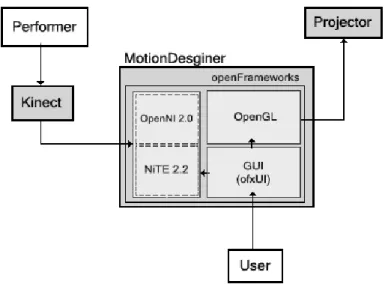
For the development of MotionDesigner, openFrameworks 0.8.4, OpenNI 2.2 and NiTE 2.2 middleware were used, along with ofxUI and ofxSecondWindow add-ons. The chosen IDE was Microsoft Visual Studio 2012 Express and for version-control it was used Git. The software architecture for MotionDesigner is depicted in Figure 4.1, which also shows how each software and hardware components were integrated. The user interacts with the software through a GUI, which sets the graphical aspect of the current graphical scene and the rules for the motion capture process. OpenGL renders the scene according to the user’s parameterization, OpenNI turns the depth sensor on when the user chooses to project the sequence and NiTE tracks the skeleton joints the user wants to be tracked.
There are two main environments that make MotionDesigner the tool we en-visioned: (1) Editing Studio, where the user can choose which graphical scenes and audio samples will be used in the interactive projection, sequence them and pre-parameterize them; and (2) Interactive Scenes/Audio Editing environment, which allows the user to explore the different possible parameterizations for each scene and for affecting the audio samples being played.
Whenever the users open MotionDesigner to create an interactive projection, the environment presented to them is (1), form which they can see the audiovisual material available to use in the projection and sequence them as they like. For
Chapter 4. Development and Implementation
Figure 4.1: System architecture. The performer interacts with the Kinect, which feeds the software with body movement data. The graphical content is rendered according to this data and and the current parameterization set by the
user through a GUI. A projector renders the scene in a plain surface.
controlling the representation and behavior of the projection element, the environ-ment (2) is presented, where the user can try different possible representations for each graphical scene and configure the motion capture rules, e.g., deactivate some joints so they do not affect the projection content. A similar environment is used to control the interaction with the sound samples played during the projection.
4.1
Editing Studio
The main environment of MotionDesigner is the one called Editing Studio. It is through this environment that the users can access all the interactive scenes and audio samples to use in the projection and where they can also call the editing environment for the interactive scenes or audio elements.
Since the users would be able to sequence the scenes and the sound sam-ples to be played during the projection as they like, the Editing Studio has a timeline-based interface. The timeline allows the users to manage the order of the audiovisual elements during the projection and the duration time for each of them. This timeline is presented to the users with a simple and minimalist design,
Chapter 4. Development and Implementation
as shown in Figure 4.2, and was created by using geometric primitives, e.g., lines and rectangles, using OpenGL’s 2D primitives drawing operations.
Figure 4.2: The Editing Studio’s timeline is represented with a simple inter-face. The user should be able to drag the time marker (in white) and see the
current time while hovering the timeline with the mouse (green)
The dimensions of the timeline take in consideration the current size of the window frame. Every time the user resizes the window, the timeline reshapes itself so that it always fits on the window frame with proper dimensions (the timeline width value depends on the window width).
For showing the current time on the time marker (white line) we used a linear relationship between the position of the markers on the screen, given where the timeline begins and ends on the screen, and the time it is supposed to show given the initial time (0 seconds) and the maximum time on the timeline (for instance 120 seconds, as on Figure 4.2). By doing so, we can get the time value to be shown in the marker in relation to the boundaries of the timeline and the maximum time of the timeline. The same principle was used for calculating the time value to display in the cursor marker (green line), but now knowing the position of the marker and wanting to know the time corresponding to that position on the timeline.
The users can control the time marker by dragging it with the mouse or by pressing the arrow keys on the keyboard. Besides this, a few more key commands were implemented and binded to the following keyboard keys:
• Left/Right Arrows - Move time marker backwards or forward in time, respectively
Chapter 4. Development and Implementation
• ENTER - Replay sequence
• +/- - Increase/decrease the timeline maximum time (sequence duration) • F - Set timeline maximum time (sequence ending) to the end of the last
scene
• DEL - Delete selected scene from the timeline
• H - Show/hide virtual skeleton on the preview player
These commands allowed the user to have a more intuitive control over the timeline, since these are standard key commands in most video editing softwares.
In order to store the graphical scenes that the user could drag to the timeline, a scenes palette panel was created. This panel has the same visual aesthetic as the timeline, as Figure 4.3 shows, with an image resembling each type of interactive scene, and a bitmap string to displaying its name. This reinforces the simple and minimalist aesthetic we are looking for in the development of the software.
Figure 4.3: A separate panel is provided with a palette of the available inter-active graphical scenes. The user can directly drag each scene from the palette
onto the timeline, in order to use them as part of the projection sequence
Whenever the users drag a scene from the scenes palette onto the timeline, they create a new timeline object, i.e., a new timeline component which can be
Chapter 4. Development and Implementation
dragged and resized within the timeline and stores all the data related to that scene (when it begins and ends on the sequence, the parameterizations it has on a given time instant, etc.). This timeline object stores the type of scene it refers to (the Particle System or the Joints Draw scene) and all the parameterizations data related to that scene. This newly created timeline object will automatically start on the instant where the last scene from the timeline ends. This kind of knowledge is made possible since all the timeline objects, i.e., all the scenes instances on the timeline, are stored in an array.
Figure 4.4: A scene on the timeline is represented as a rectangular object with text information regarding its time properties (beginning, ending and duration
variables) and the correspondent type of scene
4.1.1
Scenes Parameterizations
One of the main features of MotionDesigner ’s Editing Studio is the possibility for the users to pre-parameterize each graphical scene before projecting it. This means the users can preset the aspect and behavior of the graphical scene’s elements over the projection time, without having to do it only during the live projection. The users can still parameterize the scenes elements in real-time during the live projection, but when the timeline sequence is projected it will be rendered and computed according to these pre-parameterizations data, so it can always have a preset aesthetic.
Each timeline object (graphical scene or sound sample) has a bi-dimensional vector to store the list of parameterizations for that element. What this vector stores is the list of times instants, i.e., timestamps, that have a parameterization associated to it. A parameterization vector stores real-valued numbers, which
Chapter 4. Development and Implementation
refer to the values of the parameters we allow the user to control associated to a specific instant in time. This vector will take part of the list of vectors (list of parameterizations), as illustrated in Figure 4.5.
Figure 4.5: The parameterizations for a scene on the timeline are stored in a vector (parameterizations). Each parameterization (P ) corresponds to a vector which stores a timestamp (pt), i.e., a time instant between the beginning
and the end of the scene, and the parameters values for that scene in that instant pt (e.g., in Joints Draw scene p1, p2 and p3 refer to size, trail and
speed, respectively)
Another panel was created just to manage all the operations related with the scenes parameterizations. Through this new panel, shown in Figure 4.6 the user can access the list of existing timestamps, i.e., parameterizations, for a specific scene selected from the timeline, add timestamps to the list or delete an existing timestamp. The parameterizations panel was added to the scenes palette panel location and can be accessed through a tab selecting system.
In order to create a new timestamp with a parameterization associated to it, the user should first click on the respective scene on the timeline and then click on the corresponding button on the parameters panel (see Figure 4.6). After clicking this button, a new timestamp is automatically added to the list (a new param-eterization vector is created and added to the paramparam-eterizations vector of the selected timeline object). The timestamp value for the newly created parameter-ization is the current value on the time marker (white line on timeline) and the values of the parameters are default values (which can later be changed). If the value on the time marker is not within the beginning and ending of the selected scene from the timeline, the timestamp can not be created. If the users try to
Chapter 4. Development and Implementation
create the same timestamp twice, i.e., two parameterizations for the same time instant, they can not do it, since duplicates are not allowed in the timestamps list.
Figure 4.6: The Parameterizations Panel shows a drop-down list of the times-tamps already created for the selected scene on the timeline. On the right a sliders interface is shown, where the user can change the parameters values for that time instant. A button for adding a new timestamp is provided on the bottom left corner of this panel. The timestamps appear as red lines on the
timeline.
To allow a more efficient management of the parameterizations, specially if one wants to know which timestamp will be read next when playing back the timeline sequence, when a new timestamp is added to the list it will be added orderly, i.e., when a new parameterization vector is added to the parameterizations vector, the latter is automatically sorted according to the timestamps values, in an ascendant order. To sort the parameterizations array the Selection Sort algorithm was implemented [25]. This algorithm was chosen due to its simplicity and to the performance advantages associated to it, since this is one of the vector sorting algorithms that best preserves the auxiliary memory usage.
Chapter 4. Development and Implementation
After selecting one of the timestamps from the list, a sliders interface is shown (similar to those found on the interactive scenes GUI) where the parameters values for that time instant can be changed by the users as they desire (see Figure 4.6). If the users want to delete a timestamp parameterization they can do it by clicking on the respective button displayed on the bottom right corner of the parameteri-zations panel, after that timestamp is selected from the list.
A Paste Settings button was also added, which allows the users to set the parameters values of the currently selected timestamp to the values copied from the interactive scenes editing GUI (these copy/paste operations for the parameters values are further discussed on Section 4.1.3 of the current chapter).
4.1.2
Previewing the Projection Sequence
In order for the users to be able to preview the aspect and behavior of the scenes elements, according to the timeline sequence, before projecting it, a preview player was added to the Editing Studio environment. This is a necessary feature in order to give the users comfort and efficiency during the management of the graphical scenes to be used in the interactive projection.
A new panel was created with a small preview screen and three control buttons to control the time marker along the timeline (besides the keyboard and mouse controls already implemented). A Play/Pause button and two Skip buttons were added. The Skip buttons skip the time marker to the next (or to the previous) timestamp of the scene or, if it is on the last timestamp, to the beginning of the next scene on the timeline (and vice-versa).
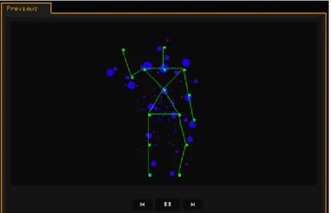
The preview player panel was ultimately placed where the Scenes Palette panel was on the original sketches (see Section A.1 of Appendix A) and it renders each scene from the timeline according to the parameters values on the current time instant (the parameters values interpolate between each timestamp). A virtual skeleton, moving in a loop routine, is also displayed so that the user can see the behavior of the content previewed in relation to the movement of a human body.
Chapter 4. Development and Implementation
Figure 4.7 shows the preview player displaying a particle system scene with the virtual skeleton reference, which can be set as visible by the user by pressing the H key on the keyboard.
Figure 4.7: The Preview Panel provides a player which previews the timeline scenes content over time. It also displays a virtual skeleton that moves with a preset of movements so that the user can see not only the visual aspect of the scene elements but also their behavior. The circles represent the particles
tracking the skeleton joints.
4.1.3
Displaying the Scenes
As depicted on Figure 4.3, each scene image from the scenes palette has a small button on the bottom left corner. This is the Explore button that in our early sketch was reserved to the control buttons area on the bottom right corner of the screen. It was found, though user testing, that clicking on a scene from the timeline or from the scenes palette and then clicking on this button on the other side of the screen was an unnecessary process. With the new solution implemented, the user can launch a specific type of graphical scene on fullscreen, in order to explore the parameterizations possibilities, by just clicking on this button on the respective scene from the scenes palette.
If the user clicks on the Explore button, represented on Figure 4.8, it launches the respective interactive scene with the GUI elements reserved for this context,
Chapter 4. Development and Implementation
which are a parameters panel, a joints selector and a color picker (these are further discussed on Section 4.2 of the current chapter).
Figure 4.8: The Explore button allows the user to launch an interactive scene and freely explore the possible parameterizations of the scene elements
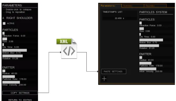
When the user launches a scene, the respective scene is presented with a default aspect and behavior but with a GUI that allows the user to change these char-acteristics in real-time by freely exploring the possible different parameterizations for that scene. On the panel where the users can change the parameters values of the scene’s elements, the parameters panel, there is a Copy Settings button, which, when clicked, writes the current parameters values of that scene in a XML file. This XML file is read whenever the user clicks on the Paste Settings button from the Parameterizations Panel of the Editing Studio. See Figure 4.9 to see the data flow in this copy/paste parameterization scenario.
By alternating between each interactive scene exploration and the editing stu-dio, where the user can sequence these scenes and pre-parameterize them along the projection time, the users can comfortably achieve the interactive audiovisual experience they want within the provided materials.
Chapter 4. Development and Implementation
Figure 4.9: Parameterizations data flow. When the users are controlling an interactive graphical scene (on the left) they can click on a Copy Settings button, which will save all the parameters sliders values into a XML file. Then, on the Editing Studio (on the right), the user can click on a Paste Settings button to set the parameters values of the currently selected timestamp to those on the
XML file.
4.1.4
Projecting the Sequence
As depicted in the Editing Studio’s interface early sketch (see Section A.1 of Ap-pendix A) the bottom right area of this environment was reserved for control buttons. A button for launching the projection sequence, i.e., the interactive scenes and audio on the timeline, was added to this area of the GUI, as shown in Figure 4.10.
When the user clicks on the Launch button a second window is created, which will render the interactive scenes as they appear on the original window but with-out the GUI elements. This window is the one which is supposed to be dragged to the projector area, i.e., to the second screen of the computer (assuming it has the projection configuration in Extend mode). This duplicated window is created using the ofxSecondWindow add-on, getting the result shown in Figure 4.11.
Chapter 4. Development and Implementation
Figure 4.10: The Editing Studio interface provides four different panels. A panel with a Preview Player on the right and on the left a panel that can show three different contents: the audio files the users can drag to the timeline, the graphical scenes they can use and the parameterizations control panel for a scene
or audio element selected from the timeline
Chapter 4. Development and Implementation
Figure 4.11: When the user launches the timeline content into the projection a second window is created without the GUI elements. It is the content of this
second window that will be shown by the projector
4.2
Interactive Graphical Scenes
Unlike other systems that have a set of images to embed with the projection or some preset graphics to be projected the way they are, like in cyclic for instance [26], in the software herein proposed the computer completely generates the graph-ics algorithmically. The aspect and behavior of the rendered scenes are dependent not only on the movement of the person interacting with the projection but also the configuration set by the conductor of the projection, which can be always changed in real-time.
For each type of graphical scene, the user should be able to control its visual aspect and behavior in real-time, which is possible due to the GUI shown in Figure 4.12.
Chapter 4. Development and Implementation
4.2.1
Scenes Editing GUI
In order to allow the users to have real-time control over the graphical scenes content, a scenes editing environment was implemented. Whenever the users are either live projecting interactive graphical content or simply experimenting each scene parameterization on the editing studio, the GUI shown in Figure 4.12 is presented to them.
Figure 4.12: Interactive Scenes Editing GUI. A sliders-based panel allows real-time parameterizations for the scene’s elements (left panel). A joints selector panel allows the user to choose to which joint the current parameterization will be associated with (upper right panel). The color of the scene’s elements can be
set through a color picker (bottom right corner).
Regarding the parameters panel (left corner of the screen), there were two different implementation options for the user to change the parameters values of the scene’s elements: either making a sliders-based UI or one based on text input. Through testing a simple implementation of each option with the users, the sliders-based UI revealed itself as the strongest candidate, since the changes to the parameters values could be performed much quicker by simple dragging a slider, allowing the users to test different values very quickly. On the other hand, if the users need to input the desired values for experimentation on a text field they first need to click on the desired text field and then press the corresponding
![Figure 1.2: “Mind the Dots” a piece where a solo dancer interacts with virtual dots creating abstract graphic shapes generated by a computer [7].](https://thumb-eu.123doks.com/thumbv2/123dok_br/19183872.946652/19.893.215.736.503.796/figure-interacts-virtual-creating-abstract-graphic-generated-computer.webp)