Universidade de Aveiro
2011
Departamento de Engenharia Cerâmica e do Vidro
Rejini Rajamma
Incorporação de cinzas volantes de
biomassa em materiais cimentíceos
Biomass fly ash incorporation in cement
based materials
Universidade de Aveiro
2011
Departamento de Engenharia Cerâmica e do Vidro
Rejini Rajamma
Incorporação de cinzas volantes de
biomassa em materiais cimentíceos
Tese submetida à Universidade de Aveiro para cumprimento dos requisitos necessários à obtenção do grau de Doutor em Ciência e Engenharia de Materiais, realizada sob a orientação científica do Prof. Doutor Victor Miguel Carneiro de Sousa Ferreira, Professor Associado do Departamento de Engenharia Civil da Universidade de Aveiro e a co-orientação do Prof. Doutor João António Labrincha Batista, Professor Associado com Agregação do Departamento de Engenharia Cerâmica e do Vidro da Universidade de Aveiro.
texto Apoio financeiro da FCT e do FSE no âmbito do III Quadro Comunitário de Apoio.
Universidade de Aveiro
2011
Departamento de Engenharia Cerâmica e do Vidro
Rejini Rajamma
Biomass fly ash incorporation in cement
based materials
Thesis submitted to University of Aveiro in partial fulfillment of the requirements for obtaining the degree of Doctor of Philosophy in Materials Science Engineering, held under the scientific guidance of Prof. Dr. Victor Miguel Carneiro de Sousa Ferreira, Associate Professor, of Department of Civil Engineering, University of Aveiro and the co-supervision of Prof. Dr. João António Labrincha Batista, Associate Professor with Aggregation Department of Ceramics and Glass Engineering, University of Aveiro
texto Apoio financeiro da FCT e do FSE no âmbito do III Quadro Comunitário de Apoio.
o júri
presidente Doutora Nilza Maria Vilhena Nunes da Costa Professora Catedrática da Universidade de Aveiro
Doutor Jorge Manuel Caliço Lopes de Brito
Professor Catedrático da Universidade Técnica de Lisboa
Doutor João António Labrincha Batista
Professor Associado com Agregação da Universidade de Aveiro
Doutor Victor Miguel Carneiro de Sousa Ferreira Professor Associado da Universidade de Aveiro
Doutor Luís António da Cruz Tarelho
Professor Auxiliar da Universidade de Aveiro
Doutora Maria Cãndida Lobo Guerra Vilarinho Professora Auxiliar da Universidade do Minho
Doutor António Manuel dos Santos Silva
Investigador Auxiliar do Laboratório Nacional de Engenharia Civil
Acknowledgements
First of all I thank my creator for providing me strength to endure and to hope for the good always.
I would like to thank my supervisors, Prof. Victor M. Ferreira and Prof. João A. Labrincha for guiding me throughout the research and in writing the thesis. I thank for their valuable supports in making this thesis.
I use this occasion to thank Foundation of Science and Technology (FCT), Portugal for providing me a PhD grant (SRFH/BD/32500/2006) with which it was possible to do this work.
It is acknowledged the financial support from Fundação para a Ciência e a Tecnologia (FCT), Portugal, through the project with reference PTDC/AAC-AMB/098112/2008 (Bias-to-soil - Biomass ash: Characteristics in relation to its origin, treatment and application to (Bias-to-soil.). I express my sincere gratitude to Prof. Luís Tarelho, Dept of Environmental Engineering, UA for giving valuable support in the collection and characterisation of biomass fly ashes. I acknowledge and am greatly thankful for the support provided by Dr. A. Santos Silva, Materials Department, LNEC, Lisbon in doing the internal expansion tests in the mortar and concretes.
I would also thank Prof Geoffrey Allen and Dr. Richard Ball, IAC Bristol, UK for their assistance in this work especially by helping with the Environmental scanning electron microscopy.
Sincere thanks to Regina M. and Dora S. who helped me in an extensive way during the work.
Much thanks to Prof. Ribeiro M. (Polytechnic Institute, Viana do Castelo), Luis P., Luciano S., Lina M., Sofia S., Ana C., Teresa E. and all those technicians and researchers in the Dept. of Civil Engineering, Dept. of Ceramics and Glass Engineering, Interface Analysis centre (IAC) Bristol, and National Laboratory of Civil Engineering (LNEC), Lisbon who helped me directly and indirectly in doing this work. I express my sincere gratitude to all including those whose names are not mentioned here but have helped me in one way or the other in making this thesis possible.
And I thank my beloved family who always gives me all courage and support by standing with me both in my ups and downs.
palavras-chave cinzas volantes de biomassa; resíduos; reciclagem; cimentos, betões e
argamassas
resumo Recentemente, as pressões ao nível da segurança, do ambiente e da energia
conduziram a uma procura crescente de fontes de energia renováveis, e à diversificação das fontes de energia da Europa. Entre estes recursos a biomassa pode ter um papel importante, uma vez que é considerada como um recurso renovável e neutra em termos de CO2 pois a taxa do consumo é mais baixa do que a taxa de crescimento e pode potencialmente fornecer energia para calor, eletricidade e transportes a partir da mesma instalação. Atualmente, a maioria da cinza de biomassa produzida em unidades industriais é disposta em aterro ou reciclada na floresta ou na agricultura e, na maioria das vezes, isto sucede sem grande controlo. Contudo, considerando que o custo da eliminação de cinzas de biomassa vem crescendo, e que os volumes da cinza de biomassa estão a aumentar, uma gestão sustentável das cinzas tem de ser implementada.
O objetivo principal deste trabalho é o estudo do efeito de cinzas volantes de biomassa em argamassas e betões com base em cimento de modo a serem usadas como um material cimentíceo suplementar. Os resíduos analisados no estudo foram colhidos de caldeiras de leito fluidizado e caldeiras de grelha disponíveis em unidades de produção elétrica e em unidades industriais de produção de pasta e papel em Portugal. As caracterizações físicas e químicas das cinzas volantes de biomassa foram efetuadas. O cimento foi substituído pelas cinzas de biomassa a fim de investigar o efeito nas propriedades no estado fresco bem com nas propriedades no estado endurecido de formulações de argamassa e betão. Reações expansivas tais como a reação alcali-sílica (ASR) e as reações sulfáticas (externas e internas) foram estudadas a fim verificar a durabilidade das argamassas e betões de cimento contendo cinzas volantes de biomassa. As aplicações alternativas tais como a incorporação de cinzas em argamassas de cal e a ativação alcalina foram também estudadas.
As partículas da cinza de biomassa eram irregulares na forma e finas. A caracterização química revelou que as cinzas eram similares a uma cinza volante da classe C. Os resultados em argamassas mostraram viabilidade para o uso de cinzas de biomassa como materiais cimentíceos suplementares em teores baixos (<20%). A trabalhabilidade, o conteúdo orgânico, o teor de alcalinos, cloretos e sulfatos são razões para impedir maiores incorporações de cinza de biomassa nas argamassas de cimento. Os resultados dos testes da durabilidade mostraram uma redução na expansão para argamassas e betões contendo cinzas de biomassa especialmente quando se misturou cinzas (20%) com metacaulino (10%). A incorporação da cinza de biomassa em argamassas de cal não melhorou as propriedades significativamente embora a carbonatação fosse maior quando da incorporação de 15 ou 20%. A mistura do metacaulino com a cinza de biomassa funcionou bem na aplicação envolvendo a ativação alcalina. Ligantes sem cimento Portland com resistência à compressão de 30-40 MPa foram obtidas pela ativação alcalina das cinzas de biomassa (60-80%) misturadas com o metacaulino (20-40%).
keywords biomass fly ashes, wastes, recycling, cement, mortar and concrete
abstract In recent years, pressures on global environment and energy security have led to an
increasing demand on renewable energy sources, and diversification of Europe’s energy supply. Among these resources the biomass could exert an important role, since it is considered a renewable and CO2 neutral energy resource once the
consumption rate is lower than the growth rate, and can potentially provide energy for heat, power and transports from the same installation. Currently, most of the biomass ash produced in industrial plants is either disposed of in landfill or recycled on agricultural fields or forest, and most times this goes on without any form of control. However, considering that the disposal cost of biomass ashes are raising, and that biomass ash volumes are increasing worldwide, a sustainable ash management has to be established.
The main objective of the present study is the effect of biomass fly ashes in cement mortars and concretes in order to be used as a supplementary cementitious material. The wastes analyzed in the study were collected from the fluidized bed boilers and grate boilers available in the thermal power plants and paper pulp plants situated in Portugal. The physical as well as chemical characterisations of the biomass fly ashes were investigated. The cement was replaced by the biomass fly ashes in 10, 20 and 30% (weight %) in order to investigate the fresh properties as well as the hardened properties of biomass fly ash incorporated cement mortar and concrete formulations. Expansion reactions such as alkali silica reaction (ASR), sulphate attack (external and internal) were conducted in order to check the durability of the biomass fly ash incorporated cement mortars and concretes. Alternative applications such as incorporation in lime mortars and alkali activation of the biomass fly ashes were also attempted.
The biomass fly ash particles were irregular in shape and fine in nature. The chemical characterization revealed that the biomass fly ashes were similar to a class C fly ash. The mortar results showed a good scope for biomass fly ashes as supplementary cementitious materials in lower dosages (<20%). The poor workability, concerns about the organic content, alkalis, chlorides and sulphates stand as the reasons for preventing the use of biomass fly ash in high content in the cement mortars. The results obtained from the durability tests have shown a clear reduction in expansion for the biomass fly ash mortars/concretes and the binder blend made with biomass fly ash (20%) and metakaolin (10%) inhibited the ASR reaction effectively. The biomass fly ash incorporation in lime mortars did not improve the mortar properties significantly though the carbonation was enhanced in the 15-20% incorporation. The biomass fly ash metakaolin blend worked well in the alkali activated complex binder application also. Portland cement free binders (with 30-40 MPa compressive strength) were obtained on the alkali activation of biomass fly ashes (60-80%) blended with metakaolin (20-40%).
CONTENTS
CHAPTER 1. INTRODUCTION... 34
1.1. Cement industry and the current environmental issues...……...34
1.2. Objective and scope of the work...38
CHAPTER 2. A LITERATURE REVIEW... 42
2.1. Introduction...42
2.2. Coal fly ash ...42
2.2.1. Physical properties ... 43
2.2.2. Chemical properties... 44
2.2.3. Hydration of fly ash cement ... 48
2.2.4. Fly ash applications... 49
2.2.5. Major research findings on coal fly ash applications in the cement/concrete industry .. 50
2.2.6. Fly ash for sustainable construction materials ... 52
2.3.1. Process and mechanisms of ash formation... 54
2.3.2. Biomass characteristics ... 57
2.3.3. Types of biomass combustion technology and their influence on the fly ash characteristics... 59
2.3.4. Research on biomass ash in construction materials ... 60
2.3.4.1. Municipal solid waste ash ...61
2.3.4.2. Rice husk ash (RHA) ...63
2.3.4.3. Sugar cane bagasse ash ...65
2.3.4.4. Wood ash...66
i). Physical and chemical properties ...67
ii). Use of wood ash as a construction material ...69
2.4. Biomass in Portugal ...70
CHAPTER 3. CHARACTERISATION OF BIOMASS FLY ASHES... 74
3.1 Biomass fly ash - collection...74
3.1.1. Biomass fly ash from grate combustion: - biomass fly ash BFA1 ... 74
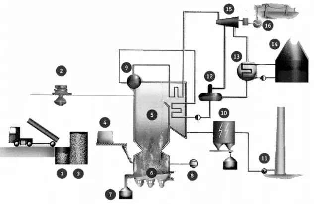
3.1.2. Biomass fly ash from fluidized bed combustion: - biomass fly ash BFA2 ... 76
3.2.1. Particle size distribution ... 78 3.2.2. Real density... 79 3.2.3. Surface area ... 79 3.2.4. Mineral characterization... 79 3.2.4.1. X-Ray Diffraction (XRD) ...79 3.2.5. Chemical characterization ... 80
3.2.5. 1. X-Ray Fluorescence Spectroscopy (XRF) ...80
3.2.5.2. X- Ray Photoelectron Spectroscopy (XPS) ...80
3.2.5. 3. Raman Imaging Spectroscopy...81
3.2.5. 4 Organic content ...81
3.2.5. 5. Determination of chlorides and sulphates ...82
3.2.6. Microstructural analysis ... 84
3.2.6. 1. Scanning electron microscopy (SEM) and Energy dispersive analysis (EDS) ...84
3.2.6. 2. Environmental scanning electron microscopy (ESEM) ...84
3.2.7. Leaching tests... 85
3.2.8. Pozzolanicity ... 87
3.2.8.1 The Frattini Test...87
3.2.8. 2. The modified Chapelle´s Test ...88
3.2.8. 3 Pozzolanic activity index (Compressive strength of mortars)...89
3.3. Results and Discussions...89
3.3.1. Particle morphology ... 89
3.3.2 Fineness... 92
3.3.3. Real density and surface area ... 94
3.3.4. Mineral Characterization... 95
3.3.4.1 X - Ray Diffraction patterns...95
3.3.4.2. Thermo gravimetric/differential thermal Analysis (TG/DTA) ...… 96
3.3. 5. Chemical Characterisation ... 97
3.3. 5. 1 X-Ray Fluorescence Spectroscopy (XRF) ...97
3.3. 5. 2 Raman Spectroscopy...100
3.3. 5. 3 Organic content ...101
3.3. 5. 4 Chloride and sulphate contents ...101
3.3.6. Microstructural analysis and surface chemistry ... 102
3.3.7. Leaching... 104
3.4. Summary...109
CHAPTER 4. BIOMASS FLY ASH INCORPORATION IN CEMENT MORTARS
112
4.1. Outline ...112
4.2. Materials and compositions ...114
4.2.1. Materials... 114
4.2.2. Mortar mix design ... 115
4.3. Experimental methods ...116
4.3.1. Consistency of cement pastes and mortars... 116
4.3.2. Setting time ... 117 4.3.3. Rheology ... 118 4.3.4. Hydration... 119 4.3.4.1. Impedance spectroscopy ...119 4.3.4.2. Temperature of hydration...121 4.3.5. Hardened properties ... 122 4.2.5.1. Mechanical strength ...122
4.2.5.2. Porosity by water absorption...123
4.3.6. Microstructure evaluation ... 123
4.3.6.1. Mercury intrusion porosimetry ...124
4.4. Results and discussion.. ...124
4.4.1. Fresh properties of biomass fly ash-cement mortars... 124
4.4.1.1. Effect of biomass fly ash incorporation on the workability and setting...124
4.4.1.2. Role of admixture on controlling the workability...127
4.4.1.3. Effect of biomass fly ashes on the rheology of the biomass cement mortars...132
4.4.2. Hydration of biomass fly ash cement pastes and mortars. ... 136
4.4.2.1. Electrical resistivity of hydrating biomass fly ash cement pastes ...136
4.4.2.2. Temperature of hydration of biomass fly ash incorporated cement pastes/mortars ...138
4.4.3. Effect of biomass fly ash incorporation on the hardened properties mortars... 140
4.4.4. Microstructure Evaluation... 145
4.4.4.1. Total porosity and pore size distribution...145
4.4.4.2. Minerals and Phases...146
4.4.4.3. Content of calcium hydroxide...153
CHAPTER 5. DURABILITY: EXPANSIVE REACTIONS: ALKALI SILICA
REACTIONS AND SULPHATE REACTIONS ... 164
5.1. Alkali silica reactions...164 5.1.1. Introduction ... 164 5.1.1.1. The reactive silica in aggregates ...166 5.1.1.2. Sources of alkalis in concrete...167 5.1.1.3. The role of alkalis in ASR mechanism ...168 5.1.1.4. Supplementary cementing materials (SCMs) as a solution to inhibit ASR ...170 5.1.2. Test Methods... 172 5.1.2.1. Standard ASTM C 1260 Test (AMBT) Method ...173 5.1.2.2. Materials for ASTM 1260 Accelerated mortar bar test (AMBT) ...174 5.1.2.3. Mixture proportions for ASTM C 1260 ...177 5.1.2.4. RILEM 3 and RILEM 4 Concrete Prism Test (CPT)...185 5.1.2.5. Mixture proportions for RILEM AAR-3 and RILEM AAR-4...180 5.1.2.6. Scanning electron microscopy and energy dispersive analysis...180 5.1.3. Results and discussion... 182 5.1.3.1. Accelerated Mortar Bar expansion Test (AMBT)...182 5.1.3.3. Micro structural analysis of ASR products ...189 5.2. Sulphate reaction...192 5.2.1. External Sulphate Reaction ... 193 5.2.1.1. Introduction...193 5.2.1.2. Experimental procedure ...196 5.2.1.3. Results and discussion...197 5.2.2. Internal Sulphate Reaction (ISR) ... 201 5.2.2.1. Introduction...201 5.2.2.3. Materials and mix proportions ...203 5.2.2.2. Experimental procedure ...204 5.2.2.4. Results and discussion...205 5.2.2.4.1. Expansion and weight variation...205 5.2.2.4.2. Strength measurements ...207 5.2.2. 4. 3. Consumption of calcium hydroxide Ca(OH)2...208
CHAPTER 6 ALTERNATIVE APPLICATIONS OF
BIOMASS FLY ASHES . 212
6.1. Introduction...212 6.2. Biomass fly ash in lime based mortars...212 6.2.1. Materials, composition design and sample preparations... 213 6.2.2. Results and discussions ... 214 6.2.2.1. Mechanical strength ...214 6.2.2.2. Microstructure...215 6.3. Alkali activation of biomass fly ashes ...219 6.3.1. Materials... 221 6.3.2. Alkaline activators... 222 6.3.3. Compositions... 223 6.3.4. Results and discussions ... 226 6.3.4.1. Compressive strength measurements ...226 6.4. Summary...232
CHAPTER 7. CONCLUSIONS AND FUTURE WORK………233
REFERENCES ………...237
Online sources... 253 Annex 1. Chapelle test calculations ... 254 Annex 2. Leaching test results by ICP. MS method ... 255 Annex 3 Mehanical strength of biomass metakaoin mortars ... 257 Appendix A. Standards ... 260 Appendix B Acronyms... 2621
TABLES
T
able 1.1. Regional and world cement production to year 2010………...34 Table 2.1. Normal range of chemical composition for fly ash produce from different coal types………...43 Table 2.2. Current chemical requirements for fly ash classification………...44 Table 2.3. Typical chemistry of the coal fly ashes in wt %, as per ASTM C 618 Standard……….46 Table 2.4. Emission reduction data in cement manufacture……….52 Table 2.5. The major biomass materials of industrial interest on a worldwide basis…...57 Table 2.6. Typical ash elemental analysis data (major elements) for a number of biomass materials………...57 Table 3.1. Particle size distribution ………..93 Table 3.2. Surface area of the typical fractions of the biomass fly ashes………..94 Table 3.3. XRF analysis of biomass fly ashes………...97 Table 3.4. Summary of chemical composition of wood waste ash ………..99 Table 3.5. Organic content in the biomass fly ashes………...100 Table 3.6. Chloride and sulphate content of biomass fly ashes………...101 Table 3.7. Summary of XPS analysis on cement and the fly ash samples………..103 Table 3.8. Total weight of the element in the dry residue of the nonleached sample (wGT) and theproportion by weight of the leachable amount (wR )(%) ………...106
Table 3.9. Comparison between ICP-MS and XRF methods………..107 Table 3.10. Pozzolanic behaviour of the biomass fly ashes………108 Table 4.1. Chemical composition of the cement determined by XRF analysis………...113 Table 4.2. Mix proportions used for biomass fly ash cement mortars with no superplasticizer….115 Table 4.3. Fresh properties of biomass fly ash –cement mortars without superplasticizer……….126 Table 4.4. The designations of mortars with superplasticizer added in %...127 Table 4.5 Mortar compositions with 0.35% SP and w/b 0.55……….128 Table 4.6. Mortar compositions with 0.75% SP and w/b 0.55………128 Table 4.7. Crystal phase compounds name and chemical formula………..146 Table 5.1. List of alkali-silica reactive minerals and possible rock types………...166 Table 5.2. Chemical composition of the cement determined by XRF analysis………..174 Table 5.3. Aggregate size distribution for AMBT test………...……….174
Table 5.4. Chemical composition of the biomass fly ashes and metakaolin……….175 Table 5.5. The composition of the test mortars………...176 Table 5.6. Mortar formulations ………...177 Table 5.7. Classes of aggregate reactivity (ASTM C 1260, RILEM AA3)……….178 Table 5.8. Composition of Concretes - RILEM TC-106-3 (AAR-3 and AAR-4)………...179 Table 5.9. The ASR mitigating efficiency of the biomass fly ash mortars……….186 Table 5.10. Mortar compositions for ESR tests ……….……….196 Table 5.11. Classes of sulphate concentration in solid and water………...196 Table 5.12. Mixture Proportions of 30% BFA2 concrete for ISR test………203 Table 6.1. Mix proportions for biomass fly ash lime mortars……….214 Table 6.2. Mercury Intrusion Porosimetry data summary………...216 Table 6.3. Capillary coefficient values of biomass fly ash-lime mortars………219 Table 6.4. Applications of geopolymers………..221 Table 6.5. The major oxides in precursor materials………...….222 Table 6.6. Mixture compositions of alkali activated biomass fly ashes………..225 Table 6.7. Mixture proportions for biomass fly ash metakaolin mortar blends………..225 Table 6.8. Mechanical properties of alkali activated biomass fly ash……….227 Table 6.9. Relative molar mass ratios of the mixture compositions………228
FIGURES
Figure 1.1. Global CO2 production………34
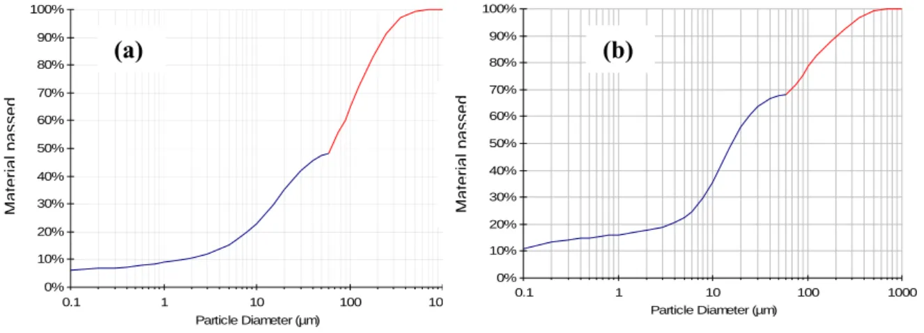
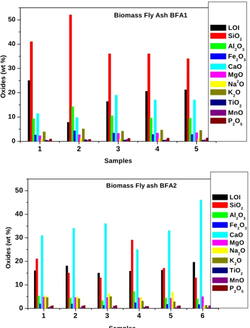
Figure 2.1. Illustration of fly ash generation in coal fired thermal power plant………42 Figure 2.2. Environmental gain for each ton of fly ash utilized………51 Figure 2.3. The combustion of a small biomass particle proceeds in distinct stages………54 Figure 2.4. Mechanism involved in biomass fly ash formation: Ash fractions formed in biomass combustion plants ……….55 Figure 2.5 Principal combustion technologies for biomass………...58 Figure 2.6. The main biomass thermal plants in Portugal. (a) Present (a) and (b) planned for the near future. (b) Main biomass thermal plants in Portugal……….71 Figure 2.7. Estimated amount of (bottom and fly) ashes produced at present………..72 Figure 3.1(a). Schematic layout of a typical thermal power plant with grate furnace………..74 Figure 3.1(b). Vibrating grate fed by spreader stokers………..75 Figure 3.2 (a) Schematic diagram of bubbling fluidised bed boiler for biomass fuels……….76 Figure 3.2 (b) Inside of a BFB boiler………77 Figure 3.3. The schematic diagram of the working of environmental scanning detector………….84 Figure 3.4. The modified Chapelle´s test apparatus……….87 Figure 3.5. Biomass fly ashes (a) BFA1 and (b) BFA2………89 Figure 3.6. ESEM pictures of 1) Biomass fly ash BFA1 and 2) Biomass fly ash BFA2…………..90 Figure 3.7. Particle size distribution of biomass fly ashes by manual sieving………..91 Figure 3.8. Particle size distribution (in volume) of biomass fly ash BFA1……….92 Figure 3.9. Particle size distribution of biomass fly ash BFA2……….92 Figure 3.10. Cumulative particle size distribution of biomass fly ashes (a) BFA1 and (b) BFA2 in terms………..93 Figure 3.11. X-Ray diffraction patterns of biomass fly ashes BFA1……….95 Figure 3.12 X-Ray diffraction patterns of biomass fly ash BFA2………95 Figure 3.13. TG/DTA analysis of biomass fly ashes BFA1………..96 Figure 3.14. TG/DTA analysis of biomass fly ashes BFA2………..96 Figure 3.15.Variation of oxides in the biomass fly ashes in several samples collected in distinct months (bimonthly) along one year………...98 Figure 3.16. Raman spectra of biomass fly ashes BFA1 and BFA2……….99 Figure 3.17 Evaluation of the trend of variation of chlorides and sulphates in the biomass fly ash samples collected in distinct months (bimonthly) along one year……… ………..101
Figure 3.18 EDX spectrum of fly ash BFA1 and the corresponding SEM mage………....102 Figure 3.19. EDX spectrum of fly ash BFA2 and the corresponding SEM image………..103 Figure 3.20. PH and conductivity of the leaching solution of the ashes samples, for the first cycle and second cycle of leaching………...104 Figure 3.21 Major elements content in the leaching solution from the ash samples, for the total leached in the two cycles………...104 Figure 3.22. Trace elements content in the leaching solution from the ash samples, for the total leached in the two cycles……….105 Figure 3.23. Pozzolanicty diagram of biomass fly ashes……….107 Figure 4.1. Experimental Design………...112 Figure 4.2. Particle size distribution of sand………...……113 Figure 4.3. Flow table apparatus……….116 Figure 4.4. VICAT apparatus………..116 Figure 4.5. (a) Viskomat PC Rheometer ……….118 Figure 4.5. (b). Bingham’s model………118 Figure 4.6 (a). Schematic diagram of impedance test apparatus……….…119 Figure 4.7. Schematic diagram of quasi adiabatic calorimeter………121 Figure 4.8. Mechanical strength determination………...122 Figure 4.9. Biomass fly ash cement paste consistency………124 Figure 4.10. The flow table values of biomass fly ash-cement mortars for different w/b ratio…..125 Figure 4.11. Setting time for biomass fly ash incorporated mortars without superplasticizer……126 Figure 4.12. The influence of super plasticizer on the flow table measurements………...129 Figure 4.13. Setting of biomass fly ash cement mortars with and without superplasticizer……...130 Figure 4.14. Flow curves (torque vs speed) of the biomass fly ash incorporated mortars at initial rotation about 10 minutes after the water addition. ………133 Figure 4.15. The evolution of torque of the biomass fly ash with time………...134 Figure 4.16. Evolution of plastic viscosity with time………..…134 Figure 4.17. Evolution of yield stress value (g) with time………..134 Figure 4.18. The resistivity curves of the biomass cement paste sample on hydration…………...135 Figure 4.19. Setting behaviour from the electrical resistivity curves………..136 Figure 4.20. Temperature evolution upon hydration of the biomass fly ash -cement pastes……..138 Figure 4.21.Effect of superplasticizer on hydration………139 Figure 4.22. Compressive Strength values of biomass fly ash BFA1 cement mortars…………...140 Figure 4.23. Compressive Strength values of biomass fly ash BFA2 cement mortars…………...140 Figure 4.24. Relative strength development of biomass fly ash cement mortars at the age of 7 days
and 28 days………..141 Figure 4.25. Relative Strength development of biomass fly ash cement mortars at the age of 90 days, 180 days and 365 days………..142 Figure 4.26. Flexural Strength values of biomass fly ash BFA1 cement mortars ………….…….143 Figure 4.27. Flexural Strength values of biomass fly ash BFA2 cement mortars……….…..143 Figure 4.28. Porosity of the biomass fly ash cement mortars by water absorption………….……145 Figure 4.29. Pore size distribution of biomass fly ash cement mortars at the age of 28 days by mercury porosimetry intrusion………145 Figure 4.30. XRD pattern of the reference cement paste at different ages of curing………..146 Figure 4.31. XRD pattern of 10% biomass fly ash cement paste at different ages of curing……..147 Figure 4.32. XRD pattern of 30% biomass fly ash cement pastes at different age of curing……..148 Figure 4.33. TG/DTA of the water cured cement paste for 2 year………..149 Figure 4.34. Thermogravimetric analysis curves of biomass fly ash substituted cement pastes at different curing ages………....150 Figure 4.35. Differential thermal analysis curves of biomass fly ash substituted cement pastes at different curing ages………151 Figure 4.36. Content of Ca(OH)2 of biomass fly ash cement paste at different curing period…..153
Figure 4.37. 10 BFA1 after 1 h of hydration………...154 Figure 4.38. Microstructure of cement-biomass fly ash pastes after 4 hours of hydration……….155 Figure 4.39. Microstructure of cement-biomass fly ash pastes after 24 hours of hydration……...156 Figure 4.40. Microstructure of cement-biomass fly ash pastes after 7 days of hydration………...157 Figure 4.41. Microstructure of cement-biomass fly ash pastes after 30 days of hydration……….158 Figure 4.42. Microstructure of cement-biomass fly ash pastes after 90 days of hydration ………159 Figure 4.43. Microstructure of cement-biomass fly ash pastes after 180 days of hydration……..160 Figure 5.1. Schematic showing differences in crystal structure of quartz (left) and opal (right)…165 Figure 5.2 . The sequence of alkali-silica reaction (ASR) in concrete………168 Figure 5.3. Cracks in a ASR damaged concrete structure………...169 Figure 5.4. Procedure of AMBT test………...173 Figure 5.5: Preparation of Concrete prisms for ASR concrete test methods……….………..180 Figure 5.6. AMBT expansion results for the reference reactive aggregate mortars………181 Figure 5.7. AMBT expansion results for single washed biomass fly ashes incorporated mortars..182 Figure 5.8. Expansion values of AMBT mortars on the14th day for different substitution compositions………182 Figure 5.9 . pH, conductivity and the major elements of the leached solutions of the batch B1-one time washed, and batch B2. five time washed) biomass fly ashes………..………183
Figure 5.10. AMBT expansion results for the multiple washed fly ash compositions………185 Figure 5.11. Expansion results at 14 and 28 days according ASTM C 1260/ASTM C 1567 method……….185 Figure 5.12. RILEM AAR 3 test results for the reference concrete………187 Figure 5.13. RILEM AAR 3 test results for the 20BFA2+10MK concrete………187 Figure 5.14. RILEM AAR 4 test results for the a) the reference and b) the 20BFA2+10MK concretes………..188 Figure 5.15. a) ASR amorphous gel in the 20 BFA1+10 MK mortar; (b) crystalline ASR in the 20 BFA1+10 MK mortar; (c, d) Crystalline ASR products inside air voids in the BFA2 mortar; (e) crystalline and amorphous ASR gel in BFA2 mortar……….. ……… …189 Figure 5.16. SEM/EDX of ASR gels formed in the polished mortars of a) 20F1+10M and b) 20F2+10M c) 20F1 and d) 20F2mortars at 28 days in ASTM C 1260 tests………190 Figure 5.17. The expansion vs Ca/Si ratio of the biomass fly ash blended cement mortars of AMBT test after 28 days of curing………...191 Figure 5.18. Deterioration in concrete due to sulphates………..193 Figure 5.19. Conditions for sulphate reactions………194 Figures 5.20. Compressive strength of chemically treated biomass fly ash mortars………...197 Figure 5.21. Expansion and variation in weight of mortars under ESR test………...197 Figure 5.22. Mortar samples selected for strength measurements at 365 days of curing…………198 Figure 5.23. Weight loss (%) of the mortars at 365 days of curing……….199 Figure 5.24. SEM/EDX of the sulphate attacked 30BFA1 mortar after 90 days of curing………199 Figure 5.25. SEM of gypsum in the sulphate attacked mortar surface of 30BFA2 mortar after 90 days of curing………..200 Figure 5.26. Concrete heat curing cycle to promote the occurrence of DEF………..204 Figure 5.27. Effect of expansion due to DEF on the reference concrete……….205 Figure 5.28 Effect of expansion due to DEF on the 30 BFA2 concrete………..205 Figure 5.29. Effect of expansion due to DEF :comparison……….……205 Figure 5.30 modulus elasticity of the concrete specimens………..206 Figure 5.31. Compressive strength of the concrete specimens………206 Figure 5.32. The TG/DTA of the (a) reference and (b) 30BFA2 concretes………208 Figure 6.1 Strength properties of biomass fly ash incorporated lime mortars……….215 Figure 6.2. Coefficient of water absorption for the biomass fly ash incorporated lime mortars….216 Figure 6.3. Pore size distribution of the biomass fly ash lime mortars at the age of 180 days…...217 Figure 6.4(a). Curves of capillary absorption for biomass fly ash substituted lime mortars cured for 90 days……….218
Figure 6.4(b). Curves of capillary absorption for biomass fly ash substituted lime mortars cured for 180 days………...218 Figure 6.5. Carbonation in BFA lime mortars cured for 180 days………..218 Figure 6.6. Alkali activated biomass fly ashes………226 Figure 6.7. NaOH molar concentration Vs compressive strength of alkali activated biomass fly ashes……….227 Figure 6.8. Compressive strength values of biomass fly ash metakaolin mortars………...228 Figure 6.9. X-ray diffraction pattern of (a) 10M100BFA and (b) 10M60BFA40MK at 10 days of curing………...229 Figure 6.10 (a). TG/DTA curves of alkali activated biomass fly ash and biomass fly ash – metakaolin geopolymers………230 Figure 6.10 (b). TG curves of alkali activated biomass fly ash and biomass fly ash –metakaolin geopolymer-a comparison………...231 Figure 6.11. SEM picture of (a) 10M100BFA (b) 10M80BFA20MK and (c) 10M60BFA40MK.232
CHAPTER 1.
INTRODUCTION
1.1. Cement industry and the current environmental issues
In booming economies from Asia to Eastern Europe, cement is literally the glue of progress. Despite the effects of the global crisis and a poor economic growth, the graph of world cement production is ever increasing especially in developing countries. But making cement means making pollution, in the form of carbon dioxide emissions. Cement plants account for around 5% of global emissions of carbon dioxide, the main cause of global warming [source:-WBCSD 2005] [Figure 1.1].
Table 1 shows the Portland cement production till the year of 2010 in million tonnes [Hardjito, 2007]. The continued growth of key world economies results in an increasing demand for construction materials. As a consequence, the global production of cement in 2030 is projected to grow to a level roughly five times higher than its level in 1995, with close to 5 billion tonnes worldwide [OECD/IEA 2003]. This has a significant impact on the overall level of anthropogenic greenhouse gas (GHG) emissions. Currently the production of one ton of cement commonly results in the release of 0.65 to 0.95 tonnes of CO2 depending on the efficiency of the process, the fuels
used, and the specific type of cement product. As a consequence, the emissions of the global cement sector alone are very likely to surpass the total amount of CO2 emissions of the EU before
2030 [source: Nicolas et al. 2007].
This is particularly visible in emerging economies. The global cement industry is facing the challenge to sustain its business while decreasing its carbon intensity, from production processes, fuel uses and its product end use. Energy production using traditional fossil fuel sources is the major factor responsible for climatic global changes, through emission of greenhouse gases and global warming of this planet. Science tells that the world must reduce its emissions of greenhouse gases by at least 80% below 1990 levels by 2050 [source:-Nicolas et al. 2007].
Carbon dioxide emissions from a cement plant are divided into two source categories: combustion and calcinations. Combustion accounts for approximately 40% and calcinations 60% of the total CO2 emissions from a cement manufacturing facility.
Table 1.1. Regional and world cement production to year 2010 (in million tonnes) (Hardjito 2007)
Figure 1.1. Global CO2 production ( Source:. WBCSD 2005)
This is the basic problem the cement production faces in reducing the CO2 emission as it is the
chemical reaction that creates it that releases large amounts of carbon dioxide. The remainder is
1995 2000 2005 2010 % of total
1995 % of total 2010
European Union 168.1 187.9 194.1 189.3 12.1 9.7
Other Europe 65.8 80.0 90.2 94.7 4.7 4.9
Former Soviet Union 58.1 80.3 110.1 128.2 4.2 6.6
North America 92.9 94.9 94.8 94.7 6.6 4.9 C/S America 89.4 106.6 127.4 145.0 6.4 7.5 Africa 64.8 74.3 80.7 85.5 4.6 4.4 Middle East 63.5 75.6 76.9 73.4 4.6 3.8 East Asia 623.4 732.7 798.8 844.3 44.6 43.4 S/SE Asia 161.2 219.1 255.0 279.2 11.6 14.4 Oceania 8.0 10.6 11.1 11.8 0.6 0.6 World totals 1396.1 1662.1 1839.1 1946.1 100.0 100.0
produced from the fuels used in production, although those emissions may be mitigated with the use of greener technology.
The chemical composition of a typical Portland cement clinker is almost entirely just four oxides: calcium oxide or lime (CaO), about 65%; silica (SiO2), about 22%; alumina (Al2O3), about 6%; and
iron oxide (Fe2O3), about 3%. In cement industry shorthand, these four oxides are written in as C,
S, A, and F, respectively, and most clinkers do not show deviations in these oxide proportions of more than 2 to 4 percentage points. The remaining 4% or so of the clinker composition is divided among oxides of magnesium, potassium, sodium, sulphur, and others. Clinker is primarily made up of four clinker minerals, denoted in shorthand as tricalcium silicate; (CaO)3 SiO2 orC3S, dicalcium
silicate ;(CaO)2 SiO2 or C2S, tricalcium aluminate; (CaO)3Al2O3 or C3A, and tetracalcium
aluminoferrite (CaO)4Al2O3Fe2O3 or C4AF. The C3S and C2S are the main contributors to the
performance of Portland cement and together make up about 70% to 80% of the weight of the clinker. During their hydration, C3S and C2S combine with water by similar reaction paths to form
calcium silicate hydrate (its variable composition is denoted as “C-S-H”) plus calcium hydroxide (CaOH)2; the C-S-H is a colloidal gel that is the actual binding agent in the concrete. The bulk of
the C3S hydrates rapidly (hours to days) and provides most of the early strength of the concrete,
whereas the C2S hydrates slowly (days to weeks) and is responsible for most of the concrete’s
long-term strength. The lime by-product of hydration activates any pozzolans that may be present in the concrete mix. The manufacture of clinker involves the thermo chemical processing of large quantities of limestone and other raw materials, typically about 1.7 t/t clinker, and requires enormous kilns and related equipment, sustained very high kiln temperatures (the materials reach temperatures of about 1450ºC in order to form the key C3S mineral), and the consumption of large
amounts of energy (fuels and electricity). Clinker manufacture results in significant emissions, particularly of carbon dioxide (CO2).
Considering the scale of the worldwide cement production, even a slight decrease in the average global emissions per ton has a large CO2 reduction potential. Every 10% decrease in the cement
CO2 intensity by 2050 could save around 0.4 Gt CO2, and substantially contribute to slowing
climate change. But the cement industry´s problems are not stopped with the global warming effect; it also makes drastic consequences in the natural raw materials availability. And also because as cement requires so many raw materials such as rock, sand and water, the consumption of energy required to mine the rock and sand as well as transport the material to the factory is high. Transporting and using these resources can also put a strain on the earth.
The clear need of reducing the CO2 emission in the present world climate situations and
conservation of the non-renewable natural resources of raw materials has led to the research on finding effective solutions, among which two of them are significant in the present work of the thesis. They are,
1. Increasing the share of biomass in the combustion process in the cement kiln as well as in
other industries where the energy is produced by fuel combustion.
Natural fuels like coal are not neutral whereas biomass is considered as a renewable and CO2
neutral energy resource, once when the consumption rate is lower than the growth rate, and can potentially provide energy for heat, power and transports from the same installation. It would require a long term sustainable supply chain for biomass fuels originating from forestry, biological wastes or crops.
2. Expanding the use of additives (chemical and materials added to cement slurry to modify the characteristics) and substitutes to cement.
Conventional and advanced alternatives to Portland cement can lead to substantial CO2 reductions
ranging from 20 to 80% depending on the case. Until now, the use of additives and substitutes to Ordinary Portland Cement (OPC) clinker has been one of the most successful measures in decreasing the specific CO2 emissions from making cements. A long term clinker ratio as low as
0.75 is desirable. Such a target is still challenging since the availability of additives will not necessarily grow at the same rate as the cement demand. The alternative materials are selected on a supplementary basis to make up for chemical deficiencies of the primary limestone feed. These supplementary materials may, replace nearly all of the alumina or silica, or they may be added as “sweeteners” to boost one oxide or another. Examples of sweeteners include high-purity limestone, or calcite itself, to boost the lime content; silica sand, silica fume, or diatomite to boost silica; alumina or aluminium dross to supply alumina; or mill scale for iron. Apart from the oxide content of a proposed alternative material, plant operators consider the material’s thermochemical accessibility [Mishulovich 2003]. For example, silica sand is a commonly used supplementary silica source, yet it is hard to grind (thus increasing electricity consumption) and the component quartz (SiO2) requires high temperatures and a long exposure in the kiln to activate the silica. If
available, a more easily grindable and/or more reactive silica source might be preferable; examples include diatomite, ferrous slag, or a material containing amorphous silica, such as coal fly ash. Although many of the supplementary materials are mined products, any number of other materials, including wastes, are potentially suitable, especially if they are of low cost. Some materials contribute both oxides and energy, for example, deinking sludge from recycling and shredder fines from paper plants. Some of these materials offer process advantages; for example, certain
aluminium smelter by-products (pot liners, catalysts) not only contribute alumina, but also sufficient fluorine or calcium fluoride to act as a flux [Mishulovich 2003]. Fly ash and bottom ash from coal power plants, as well as ferrous slags, are consumed in large quantities as supplementary silica, alumina, and lime sources for clinker. Noncarbonated lime sources are of particular interest in an environmental context because they reduce the calcinations CO2 component of the process;
this is discussed in more detail later. The criteria for selecting waste materials for the kiln include appropriate chemistry (composition and reactivity), resulting cement quality, material availability, material costs (base, transportation, storage, handling, and preparation, regulatory compliance and general environmental, and public and government acceptance.
1.2. Objective and scope of the work
The present study has been conducted in the framework of a Portuguese research project (PTDC/AAC-AMB/098112/2008 (Bias-to-soil - Biomass ash: Characteristics in relation to its origin, treatment and application to soil) aiming at widening the knowledge of the use of biomass fly ash wastes in cement formulations.
The solid biomass combustion is a proven technology for heat and power production, where the technologies of fluidised bed and grate combustion are mainly used [Loo and Koppejan 2003, Yin et al. 2008]. One of the problemsassociated to biomass combustion is related with the ash, in the thermal conversion process itself (for example, slagging and fouling phenomena), and also its environmental management.
Bio fuels represent an area of diversification in the supply of fuel to the transport sector which has recorded the highest growth rates in terms of energy consumption. In Portugal, the transport sector’s energy dependency on oil, which is responsible for 42% of total imported oil consumption, is very high. The replacement of more than 300 million litres of fuel by 2010, comprising the incorporation of 10% in road fuels, bringing the EU’s objective forward by 10 years, promotes the creation of industrial plants and development of energy based agriculture. The government set the quantity of bio fuels to be exempted from ISP (tax on oil products) at 205000 tonnes in 2007. Of this amount, 4973 tonnes derive from national agricultural production. However, this figure should rise to 405000 tonnes by 2010 in light of the forecast increase of the incorporation percentage. The fiscal exemptions (ISP) have been designed to promote the use of bio fuels in the transport sector, to reduce Portuguese energy dependency and comply with the community directive establishing the
Small dedicated producers are entitled to total exemption from ISP up to a maximum global amount of 40 thousand tonnes per year.
Currently, most of the biomass ash produced in thermal power plants is either disposed of in landfill or recycled on agricultural fields or forest, and most times this goes on without any form of control. However, considering that the disposal cost of biomass ashes are raising, and that biomass ash volumes are increasing worldwide, a sustainable ash management has to be established. Besides, for a sustainable biomass to energy strategy it is essential to close the material fluxes and to integrate the biomass ashes within the natural cycles [Obernberger et al. 1997, Loo and Koppejan 2003].
The wastes analyzed in the study are collected from the fluidized bed boilers and grate boilers available in the thermal power plants and paper pulp plants situated in Portugal. An attempt was made to answer the following questions in explaining the various possibilities of the use of these wastes in the cement industry.
1. The effect and limitations of the use of biomass fly ashes in terms of cement quality and durability.
2. The benefits in the sector and country environmentally and economically by the use of biomass fly ashes.
The second chapter is a literature review of the various fine ash waste materials used in the construction and about the biomass combustion in Portugal. The current energy situation in Portugal is discussed along with the emerging possibility of the use of biomass as a renewable energy source in industrial plants in Portugal. It is preceded by the research done so far on the use of various industrial waste ashes as additives in cement. The survey on the industrial byproducts includes coal fly ashes and the biomass ashes such as the municipal solid waste (MSW), rice husk ash, bagass ash (RHA), and wood ash (forest residues), which is the focus of the present work.
The third chapter details the characterizations techniques and methods used to analyze the biomass fly ash samples. The physical as well as chemical characterisation of the biomass fly ashes were investigated. For the convenience of a detailed investigation, two types of biomass fly ashes available in Portugal were used based on the combustion processes that influence the chemical nature of the biomass fly ashes. These ashes were the representatives of biomass fly ash collected from 1) a grate furnace and 2) a fluidised bed furnace.
The fourth chapter is mainly concentrated on the effect of biomass fly ashes in the cement mortars. An evaluation of the potential of biomass fly ashes as a substitute for the ordinary Portland cement in mortar applications is carried out. The behaviour of biomass fly ash incorporated cement mortars were discussed in terms of impact on fresh as well as on the hardened properties. Cement pastes and cement mortars were prepared by replacing an ordinary Portland cement -Type I 42.5 R, by different amounts of biomass fly ashes (10%, 20% and 30% by weight of cement) in dry conditions. The fresh properties of the mortars were investigated using various methods such as flow table, initial and final setting by Vicat, and rheological studies. The hydration behavior and phase analysis were studied using quasi adiabatic calorimetry thermal analysis, X-Ray diffraction and impedance spectroscopy. The hardened properties were studied using strength measurements and porosimetry methods. The microstructure of the cement pastes were evaluated using electron microscopy. The overall performance of biomass fly ash incorporated cement pastes and mortars for a duration of two years was evaluated and a discussion on the potential use of biomass fly ashes in the replacement of cement was carried out.
The fifth chapter addresses the potential role of biomass fly ash in controlling the durability of concretes containing biomass fly ashes against expansive reactions. Alkali Silica Reaction (ASR), External Sulphate Reaction (ESR) and Internal Sulphate Reaction (ISR) tests were conducted in the biomass incorporated mortar and/or concretes. The influence of biomass fly ash in mortars as well as concrete specimens to mitigate ASR was determined. Accelerated mortar-bar tests were conducted according to ASTM C 1260/ASTM C 1567 to evaluate the behaviour of the biomass fly ash in the ASR inhibition mechanism. The concrete prism expansion tests according the RILEM AAR-3 and RILEM AAR-4 methods were also performed on selected composition to confirm the response of biomass fly ash in mortar-bar tests. The microstructures of the specimens were investigated by SEM/EDS analysis. The expansion rates and microstructures observed were compared with control specimens. The ESR tests were conducted in mortars soaked in a mixture solution of 5% sodium sulphate and 5% magnesium sulphate. The expansion and strength of mortars at different curing period upto one year were compared with that of the reference mortar. ISR reaction test was carried out on a selected composition of biomass fly ash incorporated concrete. The ISR occurring due to the delayed ettringite formation (DEF) was analyzed. The experimental procedure was in accordance to the French concrete performance test- MLPC No. 66 test method, for DEF accelerated concrete performance.
The sixth chapter is about other potential application of biomass fly ashes. The alkali solution activated biomass fly ash as an alternative for geopolymers production is studied. The influence of biomass fly ashes in the strength development of lime mortars was also investigated. The possibilities of the use of biomass fly ash in other industrial applications based on its physical chemical characterisation werare discussed to propose the future of biomass fly ash wastes in the industry.
The seventh chapter starts with the conclusions including the major findings in the research and the fure work. This investigation also provides a comprehensive database of biomass fly ash impacts on concrete applications.
CHAPTER 2
A LITERATURE REVIEW
2.1. Introduction
Considerable research is being conducted worldwide on the use of waste materials in order to avert an increasing toxic threat to the environment, or to streamline present waste disposal techniques by making them more affordable. It follows that an economically viable solution to this problem should include utilization of waste materials for new products rather than land disposal. The pozzolanic and hydraulic properties of the industrial waste ashes obtained by combustion processes make them useful for the manufacture of cement, building materials concrete and concrete-admixed products. This chapter will review the characteristics of industrial fine ash wastes such as coal fly ash, various biomass ashes such as municipal solid waste ash (MSW), sugar cane bagasse ash, rice husk ash (RHA), palm oil fuel ash, wood fly ash, their application in cement industry as cement replacement materials and the significance of biomass fly ashes in the current energy and environmental framework in Portugal.
2.2. Coal fly ash
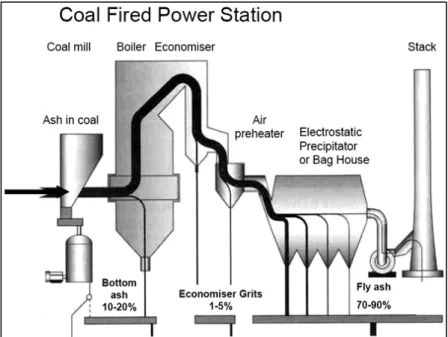
Since wide scale coal firing for power generation began in the 1920s, many millions of tons of ash and related by-products have been generated. The worldwide production of coal fly ash in the early 21st century was between 480 Mt [Feuerborn et al. 2009] and 660 Mt [Malhotra et al. 1999]. Thus, the amount of coal waste (fly ash), released by factories and thermal power plants [Figure 2.1] has been increasing throughout the world, and the disposal of the large amount of fly ash has become a serious environmental problem. The present day utilization of ash on worldwide basis varied widely from a minimum of 3% to a maximum of 57%, yet the world average only amounts to 16% of the total ash [Joshi et al. 1997]. Fly ash can be considered as the world’s fifth largest raw material resource [Mukherjee et al. 2008]. A substantial amount of ash is still disposed of in landfills and/or lagoons at a significant cost to the utilizing companies and thus to the consumers.
Worldwide, coal-fired power generation presently accounts for roughly 38% of total electricity production [OECD/IEA publications 2003]. While coal use in some of the more developed countries remains static or is in decline, significant increases in coal-fired generation capacity are taking place in many of the developing nations and large capacity increases are planned. As a consequence of the extensive investments being made in many parts of the world, and because coal
resources are far more abundant than other fossil fuel resources, and also because power plants having a long working life, coal will remain an important source of energy for many years.
During coal-fired electric power generation three types of coal combustion by-products (CCBs) are obtained. These by-products can be classified according to the zone where it is recovered from. Thus two kinds of ashes are distinguished: fly ash and bottom ash.
Figure 2.1. Illustration of fly ash generation in coal fired thermal power plant(Source www.flyashaustralia.com.au/WhatIsFlyash.aspx).
About 80% of the ash is entrained in the gas flow and it is captured and recovered as fly ash. The remaining 20% ash is the bottom ash and the economiser grits which are collected in a hopper at the bottom of the furnace. Utilization of all power plant wastes in construction industry in large quantities seems to be a reasonable solution for these environmental and economic problems. One of the main areas to utilize power plant wastes is manufacturing building materials [Ahmaruzzaman 2010].
2.2.1. Physical properties
Coal fly ash consists of inorganic matter present in the coal that has been fused during coal combustion. This material is solidified while suspended in the exhaust gases and is collected from the exhaust gases by electrostatic precipitators. Since the particles solidify while suspended in the exhaust gases, fly ash particles are generally spherical in shape either solid or hollow, and mostly
glassy (amorphous) in nature [Feuerborn et al. 2009]. The carbonaceous material in the fly ash is composed of angular particles. Fly ash particles that are collected in electrostatic precipitators are usually silt size (0.074 - 0.005mm). Although sub-bituminous coal fly ash is also silt-sized, it is generally slightly coarser than bituminous coal fly ash. The specific gravity of fly ash usually ranges from 2.1 to 3.0, while its specific surface area may vary from 170 to 1000 m2/kg
[Ahmaruzzaman 2010]. The colour of fly ash can vary from tan to gray to black, depending on the amount of unburned carbon in the ash.
2.2.2. Chemical properties
The properties of fly ash are influenced to a great extent by the properties of the coal being burned and the techniques used for handling and storage. There are basically four types, or ranks, of coal, each vary in heating value, chemical composition, ash content, and geological origin. The four types (ranks) of coal are anthracite, bituminous, sub-bituminous and lignite. In addition to being handled in a dry, conditioned, or wet form, fly ash is also sometimes classified according to the type of coal from which the ash was derived. Bituminous coal is the most common coal and is used for generating electricity, making coke, and space heating. The principal components of bituminous coal fly ash are silica, alumina, iron oxide, and calcium, with varying amounts of carbon, as measured by the loss on ignition (LOI). Lignite is more like soil than a rock and tends to disintegrate when exposed to the weather. Sub-bituminous coal is used for generating electricity and space heating. Lignite and sub-bituminous coal fly ashes were characterized by higher concentrations of calcium and magnesium oxide and reduced percentages of silica and iron oxide, as well as lower carbon content, compared with bituminous coal fly ash. Often referred to as hard coal, anthracite is hard, black and lustrous. Anthracite is low in sulphur and high in carbon. It is the highest rank of coal. Very little anthracite coal is burned in utility boilers, so there are only small amounts of anthracite coal fly ash. Table 2.1 compares the normal range of the chemical constituents of bituminous coal fly ash with those of lignite coal fly ash and sub-bituminous coal fly ash.
Table 2.1. Normal range of chemical composition for fly ash produce from different coal types (expressed as percent by weight) (Source: HRC, US DOT)
Component Bituminous Sub bituminous Lignite
SiO2 20-60 40-60 15-45 Al2O3 5-35 20-30 10-25 Fe2O3 10-40 4-10 4-15 CaO 1-12 5-30 15-40 MgO 0-5 1-6 3-10 SO3 0-4 0-2 0-10 Na2O 0-4 0-2 0-6 K2O 0-3 0-4 0-4 LOI 0-15 0-3 0-5
From the table, it is evident that lignite and sub-bituminous coal fly ash has a higher calcium oxide content and lower loss on ignition than fly ash from bituminous coals. Lignite and sub-bituminous coal fly ash may have a higher concentration of sulphate compounds than bituminous coal fly ash.
Table 2.2 explains the current limit values of chemical compositions of the fly ash for construction
purposes according to the American Society for Testing Materials (ASTM C 618) and European Standard 450 (EN 450).
Table 2.2. Current chemical requirements for fly ash classification ASTM C 618 and EN 450.(limit values).
Properties ASTM C 618 EN 450
Class F Class C Silicon dioxide (SiO2) plus aluminum oxide
(Al2O3) plus iron oxide (Fe2O3), min, %
70.0 50.0 >70.0
Sulfur trioxide (SO3), max, % 5.0 5.0 3.0
Moisture Content, max, % 3.0 3.0 -
Na2O 1.5 1.5 < 5.0
Loss on ignition, max, % 6.0* 6.0 5.0
* The use of class F fly ash containing up to 12% loss of ignition may be approved by the user if acceptable performance results are available.
Briefly, the high-calcium Class C fly ash is normally produced from the burning of low-rank coals (lignites or sub-bituminous coals) and have cementitious properties (self-hardening when reacted with water) and usually contains significant amount of calcium oxide (CaO) or lime [Cockrell et al. 1970]. This class of fly ash, in addition to having pozzolanic properties, also has some cementitious properties. On the other hand, the low-calcium Class F fly ash is commonly produced from the burning of higher-rank coals (bituminous coals or anthracites) that are pozzolanic in nature. This fly ash has siliceous or siliceous and aluminous material, which itself possesses little or no cementitious value but will, in finely divided form and in the presence of moisture, chemically
react with calcium hydroxide at ordinary temperature to form cementitious compound [Chu et al. 1993]. The chief difference between Class F and Class C fly ash is in the amount of calcium and the silica, alumina, and iron content in the ash. Color is one of the important physical properties of fly ash in terms of estimating the lime content qualitatively. It is suggested that lighter color indicate the presence of high calcium oxide and darker colors suggest high organic content [Cockrell et al. 1970].
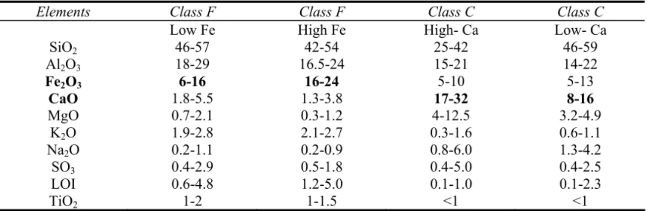
In Class F fly ash, total calcium typically ranges from 1 to 12%, mostly in the form of calcium hydroxide, calcium sulphate, and glassy components, in combination with silica and alumina. In contrast, Class C fly ash may have reported calcium oxide contents as high as 30–40% (Table 2.3). Another difference between Class F and Class C is that the amounts of alkalis (combined sodium and potassium), and sulphates (SO4), are generally higher in the Class C fly ash than in the Class F
fly ash. The mineralogical composition of fly ash, which depends on the geological factors related to the formation and deposition of coal, its combustion conditions, can be established by X-ray diffraction (XRD) analysis. The dominant mineral phases in the fly ashes are quartz (SiO2),
kaolinite Al2Si2O5(OH)4, ilite (K,H3O)(Al,Mg,Fe)2(Si,Al)4O10[(OH)2,(H2O)], and siderite (FeCO3)
[Stanislav et al. 2003]. The less predominant minerals in the unreacted coals include calcite (CaCO3), pyrite (FeS2) and hematite (Fe2O3). Quartz and mullite (3Al2O3.2SiO2) are the major
crystalline constituents of low-calcium ash, whereas high-calcium fly ash consists of quartz, Tricalcium aluminate (C3A or Ca3Al2O4), Tetra calcium aluminoferrite (C4AF orCa4AlnFe2-nO7) etc
[Stanislav et al. 2003].
The several distinct end uses of fly ash differ considerably among themselves in the stringency of the properties required in the fly ash for its successful utilization. The success of fly ash in structural fill applications rests primarily on the ability of the material to be compacted to a reasonably strong layer of low unit weight. This is primarily a function of particle size distribution, and to some extent of the content of spherical particles. The chemical characteristics of fly ash are secondary, although the post compaction cementation provided by some high-calcium fly ash is likely to prove beneficial [Ahmaruzzaman, 2010]. With highway bases chemical considerations come into play, although not in an important way. Stabilization of some base courses (and stabilized sub grades) may rest on lime fly ash chemical reactions, i.e. the classical ‘‘pozzolanic’’ reaction, with lime. Low-calcium fly ash may be entirely satisfactory or even preferred, especially where sufficient time is available for these slow reactions to take place. The only real chemical requirement is that fly ash has a sufficient content of glass that eventually will react with added lime [Diamond, 1984]. Some road base applications of fly ash depend on the physical effects of fly
ash incorporation rather than its reaction with lime. The cement and concrete end-use areas are by far the most demanding of the fly ash in terms of adherence to strict criteria and requirements. However, the requirements differ considerably depending on the specific end use involved.
Table 2.3. Typical chemistry of the coal fly ashes in wt %, as per ASTM C 618 Standard.
Elements Class F Class F Class C Class C
Low Fe High Fe High- Ca Low- Ca
SiO2 46-57 42-54 25-42 46-59 Al2O3 18-29 16.5-24 15-21 14-22 Fe2O3 6-16 16-24 5-10 5-13 CaO 1.8-5.5 1.3-3.8 17-32 8-16 MgO 0.7-2.1 0.3-1.2 4-12.5 3.2-4.9 K2O 1.9-2.8 2.1-2.7 0.3-1.6 0.6-1.1 Na2O 0.2-1.1 0.2-0.9 0.8-6.0 1.3-4.2 SO3 0.4-2.9 0.5-1.8 0.4-5.0 0.4-2.5 LOI 0.6-4.8 1.2-5.0 0.1-1.0 0.1-2.3 TiO2 1-2 1-1.5 <1 <1
Fly ash for use as a raw material in cement manufacture is sold and used primarily on the basis of its chemical composition, as expressed in the usual oxide convention. Such factors as glass content, the type of crystalline matter present, size distribution, etc., are relatively immaterial. Even high carbon content, which may be limiting in most other end uses, may actually be beneficial in cement raw material use, since it provides a definite (although modest) proportion of the fuel needed. Uniformity and chemical consistency from day to day and week to week is the prime necessity. Fly ash, as a blended cement component shares some of the requirements for both raw material and direct concrete admixture use [Diamond 1984]. Since such fly ash eventually is incorporated in concrete, its chemical and physical characteristics must be suitable for that purpose. However, since little or no adjustment can be provided at the concrete mixing stage, fly ash for use in blended cements must be of consistent and uniform chemical and physical characteristics, the consistency and predictability being as important as the numerical values of the various parameters involved. Since the blended cement manufacturer has little control over the concurrent use of chemical admixtures or of mixing and curing conditions, the fly ash used should be relatively insensitive to such variations. Especially to be considered here are rheological effects, strength development characteristics, and possibilities for developing efflorescence. The colour of the ash and its effect on the colour of the final concrete to be produced by the blended cement may also be of importance.
Because of the presence of cementitious compounds of calcium and a reactive glass, the high-calcium fly ash is also proposed suitable in Portland cement products [Oscar 1998]. Several studies are being conducted and review reports are published to better understand the complexities of alkali
aggregate reactivity and sulphate resistance with respect to fly ash in concrete [Bouzoubaâ et al. 2003, Detwiler 2002, Thomas 1996, Docter 2009, Oscar 1999, Wang et al. 2004].The availability of high-lime fly ash containing compounds found in cement has led to high-strength concretes produced by the addition of fly ash and plasticizers. High-strength and high-performance concrete can also be made with Class F fly ash. The ball bearing effect produced by the spherical fly ash particles has resulted in better pumpability of concrete and easier finishing with trowels and other tools [Oscar 1999]. The utilization of fly ash in concrete produces less permeability because of the spherical particles, and therefore improved packing, i.e. more dense paste and pozzolanic reaction. In mass concrete, with high-percentage replacement of cement with fly ash, there is a lower heat of hydration compared to straight Portland cement concrete, particularly when Class F fly ash is used. Class C fly ash may not lower the heat of hydration. Traditionally, with bituminous-type fly ash, 15–25% of the cement was replaced. The advent of cementitious, high-lime fly ash has permitted normal replacements of 25–40% and up to 75% for parking lots, driveways, and streets. A fly ash concrete mix, designed for equivalent performance to conventional concrete at normal ages, will generally gain strength more slowly at early ages. After about seven days, the rate of strength gain of fly ash concrete exceeds that of conventional concrete, enabling equivalence at the desired age. This higher rate of strength gain continues over time, enabling fly ash concrete to produce significantly higher ultimate strength than can be achieved with conventional concrete.
2.2.3. Hydration of fly ash cement
From the researches, it is known that the hydration of fly ash cement includes two processes: 1. Hydration of cement clinker and
2. The pozzolanic reaction between fly ash and Ca(OH)2 which is released in the hydration of the
cement clinker [Wang et al. 2004].
Formation of cementitious material by the reaction of Ca(OH)2 with the pozzolans (Al2O3, SiO2,
Fe2O3) is known as pozzolanic reaction. The hydrated calcium silicate gel or calcium aluminate gel
(cementitious material) can bind inert material together. For class C fly ash, the calcium oxide (lime) of the fly ash can react with the siliceous and aluminous materials (pozzolans) of the fly ash itself. Since the lime content of class F fly ash is relatively low, addition of lime is necessary for hydration reaction with the pozzolans of the fly ash. The pozzolanic reactions are as follows [Helmuth 1987]:
Ca++ + 2[OH]- + SiO2 => CSH
Ca++ + 2[OH]- + Al2O3 => CAH
Hydration of tricalcium aluminate in the ash provides one of the primary cementitious products in many ashes. The rapid rate at which hydration of the tricalcium aluminate occurs results in the rapid setting of these materials, and is the reason why delays in compaction result in lower strengths of the stabilized materials. As well as CSH, other important hydration products may include carboaluminate hydrate (C3A.CC.H12 C4AH13 solid solution) and other calcium aluminate
hydrates such as hydrogarnet (C2AH8) [Takemoto & Uchikawa 1980].
2.2.4. Fly ash applications
Coal fly ash can be utilized in the following ways [Dunstan et al. 1980].
i) High Volume Uses
High volume utilization of fly ash includes
o as structural fills in embankments, dams, dikes and leves, and o as sub-base and base courses in road way construction.
ii) Medium Volume Uses
This includes the use of fly ash
o as raw material in cement production o as an admixture in blended cements and
o as replacement of cement or as a mineral admixture in concrete. o used as partial replacement of fine aggregate in concrete.
o for production of lightweight aggregates for concrete and many other applications.
iii) Low Volume Uses
This includes the coal ash utilization
o in high value added applications such as metal extractions. High value metal recovery of Aluminum (Al), Gold (Au), Silver (Ag), Vanadium (Va) and Strontium (Sr) fall in this category.
o Fly ash has potential uses for producing light weight refractory material and exotic high temperature resistant tiles.
o Cenospheres or floaters in fly ash are used as special refractory material and also as additives in forging to produce high strength alloys.
![Figure 2.3. The combustion of a small biomass particle proceeds in distinct stages Source: [Loo and Koppejan 2008]](https://thumb-eu.123doks.com/thumbv2/123dok_br/15864536.1087270/52.892.202.691.154.416/figure-combustion-biomass-particle-proceeds-distinct-source-koppejan.webp)