Collaborative learning based on a
micro-webserver remote test controller
J. M. Ferreira
1, E. Sousa
1and A. Nafalski
2, J. Machotka
2, Z. Nedic
2 1Faculdade de Engenharia (DEEC), Porto, Portugal
2University of South Australia (SEIE), Adelaide, South Australia
Abstract— This paper presents a remote test workbench that was developed to support on-line assignments dealing with the IEEE 1149.1 standard test access port and boundary-scan architecture. The remote test controller is based on the DS80C400 networked microcontroller from Maxim-Dallas, which offers a very cost-effective solution to the development of micro-webservers enabling low-complexity data acquisition and control tasks. All remote experiments are integrated into Moodle in exactly the same way as the remaining courseware that is made available to the students. The use of Moodle facilitates the implementation of collaborative learning activities based on the remote test workbench, and the development of the workbench itself is the subject of a collaborative learning project involving students from the universities of Porto in Portugal and South Australia at Adelaide.
Index Terms— Collaborative learning, e-learning, remote laboratories, micro-webservers.
I. INTRODUCTION
Remote laboratories, also known under the name of on-line laboratories, remote workbenches, etc., found a widespread acceptance during the last decade [1:3]. It is important to distinguish remote labs from virtual labs, the difference being that the former deal with real physical devices accessible through a communications network, while the latter deal with simulation models and may or may not require an Internet connection. Remote labs do not replace real labs (they are not meant to), but they offer a range of benefits that can significantly improve pedagogical success: 1) they adapt to the pace of each student; 2) an experiment may be concluded from home, if the time available at the lab was not sufficient; 3) it can be repeated to clarify doubtful measurements obtained at the lab; 4) the student may improve the effectiveness of the time spent at the lab by rehearsing the experiment beforehand; 5) safety and security are improved, since there is no risk of catastrophic failures. These and other reasons explain why remote labs captured the attention of the academic community, and originated much research and development effort in recent years.
This paper presents a remote workbench that supports a set of lab assignments belonging to a digital electronics test course. The technological context underlying this remote test workbench is presented in the following section, which describes the knowledge domain addressed by the course and the technology used to set up the remote experiments. Section III presents the system architecture, and comprises three subsections, describing
the remote test controller, its initialization, and the test operations and closing procedures. Section IV presents the software layer, addressing the client side and the server side separately. The integration of the remote test workbench into Moodle, and the collaborative learning opportunities offered, are addressed in section V. Finally, the main conclusions and directions for further development are presented in section VI.
II. THE TECHNOLOGICAL CONTEXT
The remote labs project described in this paper uses Maxim-Dallas micro-webserver technology [4] to develop a remote workbench supporting IEEE 1149.1 boundary-scan test [5] lab assignments. This section summarises how our proposed solution works and what it does.
A. Brief description of the IEEE 1149.1 standard The widespread usage of surface mount technology and the increasing complexity of microelectronics technology led in the mid-1980s to the development of embedded test technology that was able to complement (and in some cases even replace) in-circuit and functional test solutions. A consortium initiated by Philips NL developed a test logic infrastructure that is equivalent to an electronic bed-of-nails, providing control and observation of every functional pin, without requiring physical access to internal nodes of the board under test. This test infrastructure is represented in Fig. 1 and was quickly approved by the IEEE under the name of Standard Test Access Port and Boundary-Scan Architecture, providing a simple and effective solution to detect structural faults in digital printed circuit boards.
As seen in Fig. 1, each IEEE 1149.1 chip comprises a boundary-scan (BS) register (highlighted path) that associates a boundary-scan test cell to each functional pin of the device. Detection of structural faults is done as illustrated in Fig. 2, by using the BS cells to decouple the internal logic from the pins, and shifting an appropriate test vector to the suspected fault location. If a short-circuit is present, as represented in Fig. 2, one of the logic values captured at the receiving BS cells will be different from the values shifted into the driving cells. A single 4-pin test connector (the Test Access Port – TDI and TDO for scanning Test Data In and Out, TMS for Test Mode Select, and TCK for Test Clock) allows direct access to every BS pin in the printed circuit board, enabling test
Figure 1. The IEEE 1149.1 boundary-scan infrastructure
Figure 2. Structural fault detection via IEEE 1149.1.
Figure 3. Architectural overview of an application based on the evaluation kit.
vector application and response capturing, without requiring physical contact to the interconnects under test.
Due to its quick acceptance by the industry, boundary-scan is a prominent subject in every digital test course. An on-line workbench offering remote access to a test controller and demonstration boards with selectable fault injection is therefore a valuable tool to support practical classes in this domain. The functions that must be supported by the test controller are essentially related to scanning test vectors and test responses, and to the application and capture of test data through the edge connectors of the board under test. This functionality can be achieved using dedicated test controllers and other PXI equipment driven through LabVIEW interfaces [6], but the high-cost of such solutions restricts a widespread implementation. However, and since we’re dealing with low-complexity data processing tasks, a low-cost solution is feasible by using a networked microcontroller board. B. The DSTINIm410 micro-webserver
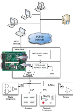
A decade after its implementation, the Maxim-Dallas TINI family offers a time and field-proven cheap solution to the implementation of micro-webservers and other Internet services [7]. Their DS80C400 evaluation kit comprises a DSTINIm410 reference board and offers a cost development solution for distributed low-complexity control and data acquisition tasks, as illustrated in Fig. 3.
The key features offered by the DS80C400 evaluation kit are [8]:
• Hosts the TINI Runtime Environment in a Validated Hardware Design (DSTINIm410) • 10/100 Ethernet Interface Connects Directly to
Standard Networks
• Three Hardware Serial Ports • One TTL Level Connectors • Two RS-232 Level Connectors • Integrated 1-Wire® Network Master • Hardware CAN 2.0B Port
• Software Support for I²C and SPI™ Ports
• Real-Time Clock (RTC) for Time/Date Stamping of Critical Transactions
• 1MB Flash ROM for Application Storage • 1MB NV SRAM for Data Storage • 5V Power Supply (Center Positive)
At a price of $109.00 USD at the time of writing, this evaluation kit offers an impressive set of tools, including APIs for I/O access and network configuration, and for managing 1-wire bus communications. It greatly simplified the implementation of the remote boundary-scan test controller, by enabling all software development tasks to be carried out in Java instead of assembly.
III. SYSTEM ARCHITECTURE
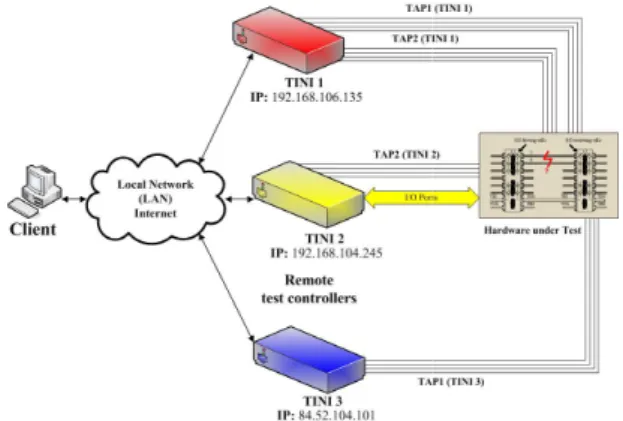
The overall representation of the proposed solution is shown in Fig. 4. Notice that a single client is able to deploy test procedures in multiple remote test controllers.
Figure 4. On-line workbench supporting remote test of boundary boards – System architecture
Figure 5. Block diagram of the remote test controller
The case of hardware under test located in multiple places is also considered in our solution. While this will be an uncommon situation, it represents an interesting scenario for collaborative learning case studies (where the hardware is located in two or more laboratories), and also when dealing with distributed systems that are expected to follow time-driven sequences in synchronized order.
A. The remote test controller
Each remote test controller may be represented according to the diagram shown in Fig. 5, which comprises the following main blocks.
• The DS80C400-Kit (the heart and brain of our proposed solution). Four parallel input / output pins of this microcontroller are used to ensure synchronization with external test hardware (SYNC channels A, B, C, and D).
• An 8-bit parallel input/output expander that connects to one or two IEEE 1149.1 tes
ports (TAP1 and TAP2).
• An additional set of parallel I/O pins providing test channels for the edge connectors of the board under test.
Notice that all parallel input / output pins, other than those of the microcontroller itself, are implemented u the 1-wire bus and the DS2408 I/O expander, offering a scalable low-cost solution that can easily adapt to the number of test channels needed for each case. Physical
line workbench supporting remote test of boundary-scan System architecture
Figure 5. Block diagram of the remote test controller Figure 6. Stacked implementation of the 1
The case of hardware under test located in multiple on. While this will be an uncommon situation, it represents an interesting scenario for collaborative learning case studies (where the hardware is located in two or more laboratories), and also when dealing with distributed systems that are driven sequences in
Each remote test controller may be represented according to the diagram shown in Fig. 5, which
(the heart and brain of our proposed solution). Four parallel input / output pins of this microcontroller are used to ensure synchronization with external test hardware (SYNC channels A, B, C, and D).
bit parallel input/output expander that connects to one or two IEEE 1149.1 test access An additional set of parallel I/O pins providing test channels for the edge connectors of the board
Notice that all parallel input / output pins, other than those of the microcontroller itself, are implemented using wire bus and the DS2408 I/O expander, offering a cost solution that can easily adapt to the number of test channels needed for each case. Physical
scalability was ensured by a stacked implementation of each set of 32 I/O channels, as illustrated in Fig. 6.
The client application handles a single test program that drives all remote test controllers. This test program is generated from a template that comprises two main parts, summarised in the following sections.
B. Server initialization
The IP addresses of each remote test controller initiate the test program template and are indicated according to the following syntax (for an example comprising two remote test controllers):
IP TINI1 192.168.106.135 IP TINI2 192.168.104.154
Each of the above program lines instructs the client application to open a connection to
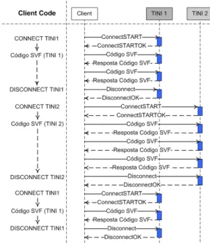
remote test controller. All test variables are then reset, and the connection is again closed, as illustrated in Fig. 7, which represents the network protocol diagram. It is important to remark that every request sent by the client application originates an acknowledgment from the remote test controllers, to ensure that any communication problems will be detected.
Once the initialization process is complete, the remote test controllers are ready to receive the sequence of commands that will define the required test operations. C. Test operations and closing
The test vectors and their expected responses, both for the boundary-scan test access ports and for the edge connectors’ inputs / outputs, are specified using a superset of the SVF test specification format [9]. The “SVF Code (TINI X)” sections in Fig. 8 correspond to the test operations that are requested by the client application. They will typically consist of scanning test data and test responses, and will
SDR N TDI(…) TDO(…) MASK(…) The SDR command Scans N
Data Register. The scan-in data follows TDI, the expected responses follow TDO, and the MASK information indicates when data is meaningful (in which
Figure 6. Stacked implementation of the 1-wire expander I/O channels
scalability was ensured by a stacked implementation of s illustrated in Fig. 6. The client application handles a single test program that drives all remote test controllers. This test program is generated from a template that comprises two main parts, summarised in the following sections.
The IP addresses of each remote test controller initiate mplate and are indicated according to the following syntax (for an example comprising two
Each of the above program lines instructs the client application to open a connection to the corresponding remote test controller. All test variables are then reset, and the connection is again closed, as illustrated in Fig. 7, which represents the network protocol diagram. It is important to remark that every request sent by the client cation originates an acknowledgment from the remote test controllers, to ensure that any communication Once the initialization process is complete, the remote llers are ready to receive the sequence of commands that will define the required test operations.
Test operations and closing
The test vectors and their expected responses, both for scan test access ports and for the edge / outputs, are specified using a superset of the SVF test specification format [9]. The “SVF Code (TINI X)” sections in Fig. 8 correspond to the test operations that are requested by the client application. They will typically consist of scanning test will be specified as follows: SDR N TDI(…) TDO(…) MASK(…)
N bits through the selected in data follows TDI, the expected responses follow TDO, and the MASK ata is meaningful (in which
Figure 7. Network protocol diagram for initializing (two) remote test controllers.
Figure 8. Network protocol diagram for the test operations and closing sequence
Figure 9. Software layers (Client and Server sides)
Figure 10. Client application.
bit positions the expected data should match the scan-out data).
Notice that Fig. 8 shows successive connect / disconnect actions to the various remote test controllers. The (dis)connection sequence is determined by synchronisation requirements among the existing test controllers / boundary-scan chains. When the suspected fault locations include pins belonging to different boundary-scan chains (eventually connected to different remote test controllers), the test response sequence can only be initiated after the test vectors are applied to all scan chains. When the SVF test program completes its execution, a closing sequence takes place to clean all test variables and leave the remote test controllers in the reset condition.
IV. THE SOFTWARE LAYER
As indicated by the system architecture represented in Fig. 4, the software layer comprises two main components – the client application and the code running in the remote test controllers (the micro-webserver code). A simplified structure depicting the main blocks residing in the client and server sides is shown in Fig. 9.
These two components will be briefly described in the following sections.
A. The client side
The client application was developed in Java and comprises two text boxes, as illustrated in Fig. 10. The upper box shows the SVF test program, and indicates which line is being executed at each moment. The lower box logs status information retrieved after the execution of each SVF command. The client application supports the following functions:
• New file (to initiate a new SVF test program from scratch)
• Open an existing SVF test program / template file • Save / Save as... the current SVF test program • Syntax check (for the SVF test program lines) • Run all SVF test program lines
• Single-step through the sequence of SVF test program lines
The client application works as an interpreter, requesting specific test operations from the remote test
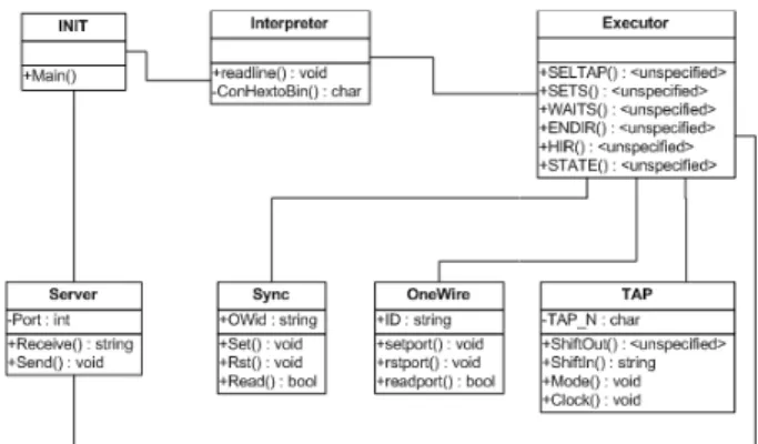
Figure 11. Class diagrams of the software residing in the server side
controller, in accordance to the sequence of SVF program lines. Some SVF commands will not send any requests to the remote test controller, e.g. all I/O mapping commands. Our implementation extended the original SVF set to enable additional test operations that are occasionally needed, such as conditional and unconditional jumps (which are also local to the client). B. The server side
The micro-webserver code residing in the DSTINIm410 remote test controller board processes all requests from the client application. It
according to the diagram represented in Fig. 11, and comprises the following classes:
• The INIT class, with the main method
• The Server class, with the methods to manage communications using sockets
• The Interpreter class has one method that receives and analyses a string
corresponding SVF command
parameters
• The Executor class contains implement and execute each SVF
• The Sync class that manages the Sync port • The OneWire class that contains
to manage 1-wire devices
• Finally, the TAP class that manages the access ports (TAP1 and TAP2)
V. INTEGRATION INTO MOODLE AND COLLABORATIVE LEARNING
Any remote lab developed for academic purposes is essentially an extension of the e-learning platform already used to deliver other pedagogical contents. In that sense, all remote experiments are basically learning objects that will be integrated into Mood
learning platform. Their interaction with Moodle, and particularly the tools and resources made available to exploit collaborative learning activities supported by the on-line workbench hosting those remote experiments, assumes a vital importance towards a successful pedagogical outcome.
A. Session scheduling
In most situations, the number of students or student groups will be higher than the number of remote test controller workbenches available. This mismatch calls for
Figure 11. Class diagrams of the software residing in the server side
Figure 12. Weekly view of MRBS adapted to schedule access to the remote test controller
Figure 13. Public view (shared by all course participants) showing that a one-hour slot has been reserved
controller, in accordance to the sequence of SVF program SVF commands will not send any requests to the remote test controller, e.g. all I/O mapping commands. Our implementation extended the original SVF set to enable additional test operations that are occasionally needed, such as conditional and
jumps (which are also local to the client).
code residing in the DSTINIm410 remote test controller board processes all may be described diagram represented in Fig. 11, and
with the main method
with the methods to manage communications using sockets
class has one method that a string, to determine the
command and its
the methods that SVF command class that manages the Sync port
contains the methods class that manages the two test (TAP1 and TAP2)
LE AND COLLABORATIVE
Any remote lab developed for academic purposes is learning platform already used to deliver other pedagogical contents. In that sense, all remote experiments are basically learning objects that will be integrated into Moodle or any other e-learning platform. Their interaction with Moodle, and particularly the tools and resources made available to exploit collaborative learning activities supported by the line workbench hosting those remote experiments, portance towards a successful
In most situations, the number of students or student groups will be higher than the number of remote test controller workbenches available. This mismatch calls for
a tool to facilitate coordinated sharing of the existing remote resources. Solutions to this problem have been presented in the past, but they will outdate rapidly if the manpower for recoding is not able to cope with upgrades to the e-learning platform [10]. This is particul
case of Moodle, where new versions are frequently released.
Fig. 12 and Fig. 13 demonstrate the solution that was adopted to schedule access to our
workbench, consisting of an adapted version of a Moodle optional module, entitled Meeting Room Booking System (MRBS) [11]. Notice that scheduling access to an on workbench is essentially the same problem faced by various teams sharing one or more mee
adoption of the standard MRBS module eliminates upgrading problems, since this module is a piece of open source software maintained by a S
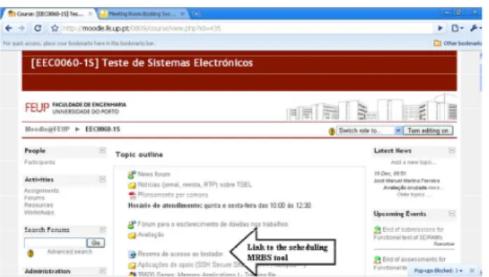
Since MRBS is a standard option that can be made available in any Moodle installation, it also serves the purpose of facilitating the integration of the remote test controller experiments as embedded learning objects, together with the remaining courseware. Fig. 14 shows how the remote experiment is seen by the course participants, in the form of a link to the scheduling
MRBS also plays an important role to support the collaborative learning objectives underlying our proposed solution. This role is reinforced by the social constructivist nature of Moodle, which was develo support learning activities addressing exploratory approaches based on teamwork and interaction among the students (notice that this model is very close to the normal learning scenarios found in laboratory assignments, where students organise themse
groups and have a reasonable degree of freedom to trial and-error using the workbench equipment). Since Moodle
Figure 12. Weekly view of MRBS adapted to schedule access to the remote test controller
course participants) showing that a hour slot has been reserved
coordinated sharing of the existing remote resources. Solutions to this problem have been presented in the past, but they will outdate rapidly if the manpower for recoding is not able to cope with upgrades learning platform [10]. This is particularly the case of Moodle, where new versions are frequently Fig. 12 and Fig. 13 demonstrate the solution that was dopted to schedule access to our remote test controller workbench, consisting of an adapted version of a Moodle optional module, entitled Meeting Room Booking System (MRBS) [11]. Notice that scheduling access to an on-line workbench is essentially the same problem faced by various teams sharing one or more meeting rooms. The adoption of the standard MRBS module eliminates upgrading problems, since this module is a piece of open
ource software maintained by a Sourceforge team. Since MRBS is a standard option that can be made
installation, it also serves the purpose of facilitating the integration of the remote test controller experiments as embedded learning objects, together with the remaining courseware. Fig. 14 shows how the remote experiment is seen by the course
f a link to the scheduling tool. also plays an important role to support the collaborative learning objectives underlying our proposed solution. This role is reinforced by the social constructivist nature of Moodle, which was developed to support learning activities addressing exploratory approaches based on teamwork and interaction among the students (notice that this model is very close to the normal learning scenarios found in laboratory assignments, where students organise themselves in groups and have a reasonable degree of freedom to
Figure 14. The link to the scheduling MRBS tool (integrating the remote experiment into Moodle).
Figure 15. Dimdim – bringing videoconferencing, whiteboard sharing and live presentations into Moodle.
supports the definition of groups, which are recognised by the various resources and activities available to deliver learning contents, this scheduling tool already handles the reservations without distinguishing between members of the same group (access to the experiment is granted to all group members within the reserved time slot).
B. Synchronous teamwork
There are many applications available that allow synchronous communication among the students when using a remote workbench from their homes. Text-based chat or video conferencing are freely available with Windows Messenger [12], Skype [13], and various other tools. Students’ acquaintance with one or more instant communication tools, such as Messenger, is not necessarily an advantage, because mixing friends and team members in the same communication space will traditionally impoverish the pedagogical effectiveness. The learning outcome of a remote experiment will benefit if the on-line workbench, the videoconferencing application, and the e-learning platform, merge into an integrated learning framework. The usage of a scheduling tool that enables coordinated sharing of the workbench among the students is a first step towards this framework. The availability of a videoconferencing application embedded into the e-learning platform is another important step towards this same objective.
Dimdim’s open source web meeting module, illustrated in Fig. 15, may be added to any Moodle 1.7.x+ installation, and was selected to support synchronous communication among the students in our current prototype [14]. Besides providing a powerful video-conferencing environment, it also offers other valuable contributions to support teamwork in remote experimentation, such as live presentations and whiteboard sharing. The integration of Dimdim into Moodle closed the gap between at-the-lab and remote experimentation, in what concerns team discussions and result sharing, and opens the way to truly collaborative learning via on-line workbenches.
CONCLUSION
The remote workbench presented in this paper is based on low-cost remote webserver technology from Maxim-Dallas. The DSTINIm410 boards offer an effective solution for the development of remote test controllers that are able to implement a wide set of on-line
experiments supporting a Moodle-based digital electronics test course offered to computer and electrical engineering students at the University of Porto in Portugal, and the University of South Australia at
Adelaide. The development work was done
collaboratively between the two universities, and provided in itself an excellent opportunity for collaborative learning involving students in the two sides of the globe. The client application and the DSTINIm410 remote micro-webserver code that support this remote test workbench were both developed in Java.
Future development is envisaged in two main areas, concerning the integration of the remote test workbench into Moodle (by further customising the adapted MRBS tool), and the customisation of the client application as an optional module that can be added to any Moodle installation.
ACKNOWLEDGMENT
The authors are grateful to Mário Pereira, who developed an initial version of the remote test controller, and to António Bandeira, who adapted the MRBS module to be used as a scheduling tool.
REFERENCES
[1] J. Ma, J. V. Nickerson, “Hands-On, Simulated, and Remote Laboratories: A Comparative Literature Review”, ACM Computing Surveys, Vol. 38, No. 3, Article 7, September 2006.
[2] T. Abdel-Salam, P. Kauffman, G. Crossman, “Does the lack of hands-on experience in a remotely delivered laboratory course affect student learning?”, European Journal of Engineering Education, Vol. 31, No. 6, December 2006, pp. 747-756.
[3] D. Gillet, A. V. Nguyen, Y. Rekik, “Collaborative Web-Based Experimentation in Flexible Engineering Education”, IEEE Transactions on Education, Vol. 48, No. 4, November 2005.
[4] M. Auer, C. Klimbacher, A. Pester, “Embedded Web Server Technology for Remote Online Labs”, Proceedings of the 2005 IEEE International Symposium on Industrial Electronics (ISIE 2005), pp. 1673- 1676.
[5] IEEE 1149.1-2001 (Revision of IEEE Std 1149.1-1990) Standard Test Access Port and Boundary-Scan Architecture, IEEE Computer Society (Test Technology Standards Committee), 25 October 2001.
[6] J. M. Ferreira, A. M. Cardoso, M. G. Gericota, "An integrated framework to support remote IEEE 1149.1 / 1149.4 design for test
experiments," 3rd Remote Engineering and Virtual Instrumentation International Symposium (REV'06), Maribor (Slovenia), June 29-30, 2006.
[7] Don Loomis, The TINI™ Specification and Developer’s Guide, Addison-Wesley, 2001, 365 pp., ISBN 0-201-72218-6.
[8] Maxim-Dallas DS80C400 evaluation kit [Online],
http://www.maxim-ic.com/quick_view2.cfm/qv_pk/4983 (visited on April 16th, 2009).
[9] Serial Vector Format (SVF) [Online], http://www.asset-intertech.com/support/svf.html (visited on April 16th 2009).
[10] J. M. Ferreira, A. M. Cardoso, "A Moodle extension to book online labs," 2nd Remote Engineering and Virtual Instrumentation International Symposium (REV'05), Brasov (Romania), June 30 - July 1, 2005.
[11] A web application for booking meeting rooms or other resources, http://mrbs.sourceforge.net/ (visited on April 21st 2009).
[12] Videoconferencing Using Windows Messenger,
http://www.microsoft.com/windowsxp/using/windowsmessenger/learn more/version45/v45videoconf.mspx (visited on April 20th 2009).
[13] Skype video calls, http://www.skype.com/allfeatures/videocall/
(visited on April 20th 2009).
[14] User Guide for Dimdim Web Meeting module in Moodle,
http://www.dimdim.com/documents/User
Guide_for_dimdim_Web_Meeting_module_in_Moodle_1_9.pdf
(visited on April 20th 2009).
AUTHORS
J. M. Ferreira and E. Sousa are with the Department of Electrical and Computer Engineering of the Faculdade de Engenharia da Universidade do Porto, 4200-465 Porto, Portugal (e-mail jmf | eduardo.sousa @fe.up.pt).
Nafalski, J. Machotka, and Z. Nedic are with the School of Electrical and Information Engineering of the University of South Australia, Mawson Lakes 5095, Adelaide, South Australia (e-mail Andrew.Nafalski | Zorica.Nedic| Jan.Machotka @unisa.edu.au).
Manuscript received 23 April 2009. Published as submitted by the author(s).