Advanced
heterogeneous
porous catalysts
for desulfurization
of diesel
Susana Natércia Oliveira Ribeiro
PhD thesis submitted to
Faculdade de Ciências da Universidade do Porto,
Faculdade de Ciências e Tecnologia da Universidade Nova de Lisboa,
Universidade de Aveiro
Catalysis
2019
D
Advanced
heterogeneous
porous catalysts for
desulfurization of
diesel
Susana Natércia Oliveira Ribeiro
Doutoramento em Química Sustentável
Departamento de Química e Bioquímica 2019
Orientador
Professor Doutor Baltazar Manuel Romão de Castro Professor Catedrático
REQUIMTE - Faculdade de Ciências da Universidade do Porto
Coorientador
Doutora Maria de La Salete da Silva Balula Investigadora Principal
To my Daughters
Helena and Isabel
Acknowledgments
This work could not have been achieved without the valuable contribution of diverse nature, so I have to thank many people and institutions for their help and availability along this journey.
First I would like to thank to my supervisor, Professor Baltazar de castro, for the opportunity to develop my thesis project and also his availability and helpful advices.
To Doctor Salete Balula, my co-supervisor, with whom has been a pleasure to work with, I would like to thank for all support, encouragement, concern and advice that helped me to overcome all the difficulties, that sometimes arised along the work.
I would also like to thank FCT (Fundação para a Ciência e Tecnologia) for the PhD grant SFRH/BD/95571/2013 and to LAQV-REQUIMTE from Departamento de Química e Bioquímica da Faculdade de Ciências da Universidade do Porto, for providing me the means for my project development.
To Doctor Luís Cunha-Silva for the good mood and encouragement, as well as all given support.
To Doctor Carlos Granadeiro for his availability and concern, as well as all the help provided every time l needed.
To MSc. Jorge Ribeiro from Galp, for the collaboration providing the untreated diesel samples and all the scientific advices that were very helpful in the positive achievements here reported. Also to Dr. Rita Valença from Galp for the sulfur content quantification in the real diesel samples.
To Professor José Campos-Martin from Grupo de Energía y Química Sostenibles (EQS), Instituto de Catálisis y Petroleoquímica, CSIC Madrid, for his collaboration providing me access to his lab, for his availability and all given support. To Maria Capel-Sanchez for accompanying me during my lab experiments and all concern and help provided. To Diana Perez and her mum, for their sympathy and affection with which they welcomed me into their home and made use of the expression "mi casa es su casa".
To Professor João Pires from the Centro de Química e Bioquímica, Faculdade de Ciências, Universidade de Lisboa for the N2-isotherms analysis and for his availability
and giving me the oportunity to visit his lab for N2-isotherms experiments which made
To Professor Valentina Domingues from LAQV-REQUIMTE, Departamento de Engenharia Química, Instituto Superior de Engenharia do Instituto Politécnico do Porto for her availability and providing me access to the GC-FPD equipment.
To Doctor Sandra Gago from LAQV-REQUIMTE, Departamento de Química, Faculdade de Ciências e Tecnologia, Universidade NOVA de Lisboa for all the help with materials characterization.
To Professor Pedro Almeida and Doctor Marta Corvo from CENIMAT/I3N, Faculdade de Ciências e Tecnologia, Universidade NOVA de Lisboa, for the MAS-NMR measurements.
To Professor Isabel Gonçalves and her research group from Associate Laboratory CICECO, Universidade de Aveiro, for all the FT-RAMAN analysis.
To my lab companions namely Diana, André and Fátima for all the help and all the good moments shared.
To all my department companions, for the good times shared and for the good work environment that makes a pleasure to go to work.
To all my closest family and friends, namely my brother and sister, for all the relaxation moments, as well as all support and encouragement.
To my parents, for the valuable life lessons, support and encouragement.
To Helder for pushing me to go further. For his understanding, love and affection. For all the support, encouragement and help given along these years of work.
To Helena and Isabel, the best that I could ever ask for. You are the best of me and the strength that helped me in the most difficult moments. This thesis is dedicated to you.
To all the people who were directly or indirectly precious in helping me to get everything going in the right direction.
Resumo
Esta dissertação teve como principal objetivo, o desenvolvimento de novos catalisadores porosos, para aplicação eficiente em processos de dessulfurização oxidativa de forma a obter-se diesel com baixo teor de enxofre. Para atingir este objetivo, o trabalho foi desenvolvido em três etapas principais: i) preparação de novos catalisadores heterogéneos; ii) otimização dos sistemas catalíticos oxidativos utilizando gasóleos modelo; iii) aplicação dos sistemas otimizados em dessulfurização de amostras de gasóleo real não tratado com diferentes quantidades e composição de enxofre.
Vários polioxometalatos (POMs) do tipo Keggin com diferentes estruturas foram selecionados como centros catalíticos ativos: i) o anião de Keggin [PW12O40]3- (PW12); o
monolacunar [PW11O39]7- (PW11); o mono-substituído [PW11Zn(H2O)O39]5- (PW11Zn) e o
tipo sanduíche [Eu(PW11O39)2]11- (Eu(PW11)2). A preparação dos catalisadores
heterogéneos foi efetuada por diferentes métodos: i) solidificação, pela combinação de POMs com o catião octadeciltrimetilamonio (ODA); ii) imobilização em suportes funcionalizados de sílica mesoporosa (SBA-15); iii) imobilização em organossílicas mesoporosas funcionalizadas (PMOs); iv) incorporação num polímero de coordenação funcionalizado (UiO-66-NH2). Todos os catalisadores foram caracterizados por
diferentes técnicas para confirmar a integridade do suporte e das estruturas dos centros ativos após a sua imobilização.
Foram estudados dois sistemas de dessulfurização oxidativa, usando H2O2 como
oxidante: i) um sistema bifásico (ECODS); ii) um sistema catalítico livre de solvente (CODS). No sistema ECODS, o processo inicia-se com uma extração líquido-líquido com MeCN ou BMIMPF6, seguindo-se a fase catalítica oxidativa na presença do
solvente de extração. No sistema CODS, a fase catalítica oxidativa é realizada na ausência de solvente, seguida por uma extração líquido-líquido final para remover os compostos de enxofre oxidado.
O sistema CODS demonstrou ser mais vantajoso na dessulfurização dos gasóleos modelo, uma vez que se utilizou uma menor quantidade de oxidante e também solventes de extração mais sustentáveis, tal como a água, para remover os produtos de oxidação do gasóleo. No entanto, o sistema ECODS apresentou resultados de dessulfurização, ligeiramente superiores, nas amostras reais de gasóleo. Os catalisadores que tiveram melhor desempenho catalítico foram aqueles contendo os
aniões derivados da estrutura de Keggin: o monolacunar [PW11O39]7- e o
mono-substituído [PW11Zn(H2O)O39]5. A maior eficiência de dessulfurização oxidativa para
tratar o gasóleo real (1335 ppm de S) foi de 93,1%, obtida na presença do catalisador PW11@TMA-SBA-15. No entanto, os compósitos monolacunares apresentaram uma
menor estabilidade em comparação com os mono-substituídos. Os compósitos PW11Zn@aptesSBA-15 e PW11Zn@aptesPMOE apresentaram uma atividade e
estabilidade semelhantes usando o gasóleo modelo (dessulfurização completa após 1 h), podendo ser reciclados durante 10 ciclos consecutivos sem perda de atividade catalítica; no tratamento do gasóleo real o compósito PW11Zn@aptesSBA-15
apresentou uma maior quantidade de centro ativo imobilizado e um melhor desempenho catalítico (87.7%).
Palavras chave: Dessulfurização oxidativa; Peróxido de hidrogénio; Derivados de
benzotiofeno; Polioxometalatos; SBA-15; Organossílicas mesoporosas periódicas; Redes metal-orgânicas; UiO-66; Gasóleol não tratado
Abstract
This work had as main objective, the development of new efficient solid catalysts, for application in oxidative desulfurization processes to prepare low-sulfur diesel. To achieve this purpose, the work was developed in three main steps: i) preparation of novel heterogeneous catalysts; ii) optimization of oxidative catalytic systems using model diesel; iii) application of optimized oxidative desulfurization systems to treat different real diesels containing different sulfur amount and composition.
Several Keggin derivative structures of polyoxometalates (POMs) were selected as active catalytic centers: i) the Keggin phosphotungstate anion [PW12O40]3- (PW12); the
monolacunar [PW11O39]7- (PW11); the zinc mono-substituted [PW11Zn(H2O)O39]
5-(PW11Zn) and the sandwich-type [Eu(PW11O39)2]11- (Eu(PW11)2). The preparation of solid
catalysts was achieved by different methods: i) solidification, by combining the anionic active center POM and octadecyltrimetylammonium (ODA) cation; ii) immobilization in functionalized mesoporous silica SBA-15 supports; iii) immobilization in functionalized periodic mesoporous organosilicas (PMOs) supports; iv) incorporation in a functionalized Metal-Organic Framework (UiO-66-NH2). All catalysts were characterized by different
techniques to confirm the integrity of support and active center structures after immobilization.
Two different desulfurization systems were studied, using H2O2 as oxidant: a
biphasic extractive and oxidative desulfurization (ECODS) system and a solvent-free catalytic oxidative desulfurization (CODS) system. The ECODS system consists in an initial liquid-liquid extraction with MeCN or BMIMPF6, followed by the oxidative catalytic
stage in the presence of the extraction solvent. In the CODS system the oxidative catalytic stage is performed in the absence of solvent, followed by a final liquid-liquid extraction to remove the oxidized sulfur compounds.
The solvent-free system demonstrated to be more advantageous, to desulfurize model diesels, since it was able to use less oxidant amount and also more sustainable extraction solvents, such as water, to remove the oxidation products from diesel. However, the biphasic system presented slightly higher desulfurization results using real diesel samples. The most active catalysts were those containing Keggin derivatives: monolacunar [PW11O39]7- and mono-substituted [PW11Zn(H2O)O39]5- as active center.
The highest oxidative desulfurization efficiency to treat real diesel (1335 ppm of S) was 93.1%, achieved using PW11@TMA-SBA-15 catalyst. However, lower stability was
found for the monolacunary composites, compared to the mono-substituted composites. Similar activity and stability were found for PW11Zn@aptesSBA-15 and
PW11Zn@aptesPMOE composites, using model diesel (complete desulfurization after 1
h), being able to be recycled over 10 consecutive cycles without loss of activity. However, higher catalytic performance treating real diesel was achieved using PW11Zn@aptesSBA-15 (87.7%).
Keywords: Oxidative desulfurization; Hydrogen Peroxide; Benzothiophene derivatives;
Polyoxometalates; SBA-15; Periodic Mesoporous Organosilica; Metal Organic frameworks; UiO-66; Real diesel
Thesis outline
This thesis is divided into ten chapters: Chapter 1 (introduction), Chapters 2-9 published or in submission process for publication results and Chapter 10 the concluding remarks and future perspectives.
The first chapter is an introduction with a general description of the aim of the project and a bibliographic review.
The Chapters 2-9 present an adaptation from published and submitted publications in which the author has a major contribution. Consequently, some similar introductory and experimental information was recurrent between chapters. The Chapters were organized in a manner that does not reflect the order of experimental work execussion, but to simplify the overall reading of this thesis and better present the obtained results. Images and additional text were added in order to present additional results, as well as to provide a better work presentation.
Chapter 10 presents a general conclusion of the main results obtained, concerning the global aim of this thesis. Final remarks and some indications for future work activities are also presented in this chapter.
Index
Acknowledgments………... v Resumo……….. vii Abstract……….. ix Thesis outline……… xi Index……….... xiiiList of figures...………. xix
List of schemes..……….. xxx
List of tables………... xxxi
Abbreviations and symbols………. xxxiii
Chapter 1 – Introduction...………... 1
Chapter index……….……… 2
1.1. Context………... 3
1.2. Crude oil and desulfurization demand………. 3
1.3. Hydrodesulfurization………... 7
1.4. Oxidative desulfurization (ODS)…………...……… 9
1.4.1. General description of ODS process………...…… 9
1.5. Polyoxometalates……… 12
1.5.1. Keggin anion……….. 13
1.5.1.1. Keggin derivatives………... 14
1.6. POM-based heterogeneous catalysts in ODS processes……… 16
1.6.1. Solidification of POMs with counter-cations………... 17
1.6.2. Immobilization of POMs in support materials………. 21
1.6.2.1. Ordered mesoporous silica……… 21
1.6.2.2. Periodic mesoporous organosilicas……….. 24
1.6.2.3. Metal-organic frameworks……….. 25
1.6.2.3.1. Metal-organic frameworks as catalysts……… 26
1.6.2.3.2. Metal-organic frameworks as supports……… 28
1.7. General plan……… 31
1.8. References……….. 32
Chapter 2 - Catalytic oxidative/extractive desulfurization of model and untreated diesel using hybrid based zinc-substituted polyoxometalates……... 43
Chapter Index……….……….. 44
Abstract………... 45
2.1. Introduction………... 46
2.2.1. Hybrid catalysts characterization ………...………. 47
2.2.2. Biphasic extractive and catalytic oxidative desulfurization (ECODS) using a model diesel….………. 50
2.2.2.1. Optimization of ECODS system……….. 51
2.2.2.2. Comparison of desulfurization efficiency between hybrid PW11Zn catalysts………. 54
2.2.2.3. Recyclability of the ECODS system………... 57
2.2.3. Desulfurization of untreated diesel………... 59
2.3. Conclusions………... 61
2.4. Experimental section……… 62
2.4.1. Materials and Methods…………..………...……….. 62
2.4.2. Synthesis of hybrid zinc-substituted polyoxometalates……… 63
2.4.3. ECODS process using a model diesel……… 64
2.4.4. ECODS process of untreated diesel……… 65
2.5. References………. 65
Chapter 3 - Improving the catalytic performance of Keggin [PW12O40]3- for oxidative desulfurization: ionic liquids versus SBA-15 composite………... 69
Chapter Index...………... 70
Abstract………... 71
3.1. Introduction………... 72
3.2. Results and discussion……….. 73
3.2.1. Catalysts characterization………...………... 73
3.2.2. Biphasic extractive and catalytic oxidative desulfurization (ECODS) process………. 77
3.2.2.1. ECODS using homogeneous IL-PW12…..………... 77
3.2.2.2. ECODS using heterogeneous PW12@TMA-SBA-15...……... 80
3.2.3. Catalyst stability………... 83
3.2.4. ECODS of untreated Diesel……….. 85
3.3. Conclusions……….. 85
3.4. Experimental section……….. 86
3.4.1. Materials and Methods…………..………...………….. 86
3.4.2. Synthesis of catalysts……….……… 88
3.4.2.1. Ionic liquid-polyoxometalates…………..……….. 88
3.4.2.2. PW12@TMA-SBA-15 composite………... 89
3.4.3. Extractive and catalytic oxidative desulfurization process………... 89
Chapter 4 - Oxidative desulfurization strategies using Keggin-type
polyoxometalate catalysts: biphasic versus solvent-free systems...…………... 95
Chapter Index...………... 96
Abstract………..………... 97
4.1. Introduction………... 98
4.2. Results and discussion………. 99
4.2.1. Catalysts characterization………...………. 99
4.2.2. Oxidative desulfurization processes using model diesel...…………. 106
4.2.2.1 Homogeneous catalysts: activity and stability ….…………... 106
4.2.2.2 Homogeneous vs Heterogeneous monolacunar catalysts.... 109
4.2.2.3 Biphasic vs Solvent-free systems using PW11 @aptesSBA-15 catalyst………... 112
4.2.3. Comparison with other monolacunary based catalysts ... 114
4.2.4. Recycling capacity and stability of PW11@aptesSBA-15...……… 115
4.2.5 Desulfurization of untreated diesel…………..……… 119
4.3. Conclusions………. 121
4.4. Experimental section……….. 122
4.4.1. Materials and Methods…………..………...……… 122
4.4.2. Synthesis and preparation of the materials……….. 124
4.4.2.1. Synthesis of polyoxometalates………..……… 124
4.4.2.2. Preparation of aptesSBA-15 support..………. 124
4.4.2.3. Preparation of tbaSBA-15 support……… 125
4.4.2.4 Preparation of PW11-based composites……… 125
4.4.3. Desulfurization system using model diesel……… 126
4.4.4 Desulfurization system using untreated diesel………. 126
4.5. References……….. 127
Chapter 5 - Effective desulfurization of diesel using Polyoxometalate-based silica catalysts…...………... 133
Chapter Index……… 134
Abstract………..………... 135
5.1. Introduction………... 136
5.2. Results and discussion………. 137
5.2.1. Catalysts characterization………...………. 137
5.2.2. Oxidative desulfurization processes using model diesel...…………. 142
5.2.2.1 Recycling of PW11Zn@aptesSBA-15 catalyst….………….... 146
5.2.4. Oxidative desulfurization processes using real diesel…...……… 150
5.3. Conclusions………. 152
5.4. Experimental section……….. 152
5.4.1. Materials and Methods…………..………...……… 152
5.4.2. Preparation of POMs@aptesSBA-15 composites…….……….. 154
5.4.3. Oxidative desulfurization processes using model diesel.……… 155
5.4.4. Oxidative desulfurization processes using untreated diesels………. 156
5.5. References………... 156
Chapter 6 - Desulfurization Process conciliating Heterogeneous Oxidation and liquid extraction: Organic Solvent or Centrifugation/Water?………..…………... 161
Chapter Index……… 162
Abstract………..………... 163
6.1. Introduction………... 164
6.2. Results and discussion………. 165
6.2.1. Catalysts characterization………...………. 165
6.2.2. Oxidative desulfurization processes (ODS)………...……… 171
6.2.2.1 Biphasic extractive and catalytic oxidative desulfurization system (ECODS) system….…………... 172
6.2.2.2 Solvent-free catalytic oxidative desulfurization (CODS) system………... 175
6.2.3. Catalyst material stability………... 179
6.3 Conclusion...………. 180
6.4. Experimental section……….. 181
6.4.1. Materials and Methods…………..………...……… 181
6.4.2. Synthesis of catalysts……….……….. 182
6.4.2.1. Europium polyoxotungstate……….…..……… 182
6.4.2.2. Eu(PW11)2@aptesSBA-15 composite……..……… 183
6.4.3. Oxidative desulfurization processes……….. 183
6.5. References……….. 184
Chapter 7 - Catalytic oxidative desulfurization performance of mesoporous silica versus organosilica composites to treat model and real diesels ………... 189
Chapter Index……… 190
Abstract……….………... 191
7.1. Introduction………... 192
7.2. Results and discussion………. 193
7.2.2. Oxidative desulfurization processes using model diesel...… 202
7.2.3. Recyclability of PW11@TMA-SBA-15……...………... 204
7.2.4. Catalysts stability………..…...……… 205
7.2.5. Oxidative desulfurization processes using untreated diesel……… 208
7.3. Conclusion………... 209
7.4. Experimental section……….. 210
7.4.1. Materials and Methods…………..………...……… 210
7.4.2. Synthesis of the materials……… 212
7.4.2.1. Synthesis of monolacunary phosphotungstate...……… 212
7.4.2.2. PW11@TMA-SBA-15 composite……… 212
7.4.2.2. PW11@TMA-PMO composites……….. 212
7.4.3. Oxidative desulfurization processes using model diesel.…………. 213
7.4.4. Oxidative desulfurization processes using untreated diesel………. 214
7.5. References……….. 214
Chapter 8 - Polyoxometalate@Periodic mesoporous organosilicas as effective catalyst for oxidative desulfurization of model and real Diesels.......……… 219
Chapter Index……… 220
Abstract……….………... 221
8.1. Introduction………... 222
8.2. Results and discussion………. 223
8.2.1. Catalysts characterization………...………. 223
8.2.2. Oxidative desulfurization processes using model diesel...…………. 230
8.2.3. Catalysts recyclability ……...………... 233
8.2.4. Catalysts stability………..…...……… 234
8.2.5. Oxidative desulfurization process using untreated diesel………….. 237
8.3. Conclusion………... 238
8.4. Experimental section……….. 238
8.4.1. Materials and Methods…………..………...……… 238
8.4.2. Preparation of materials………..… 240
8.4.2.1. Synthesis of zinc mono-substituted phosphotungstate….… 240 8.4.2.2. PW11Zn@aptesPMOs composites….……….. 240
8.4.3. Oxidative desulfurization processes using model diesel.……… 241
8.4.4. Oxidative desulfurization process using real diesel……..………… 242
Chapter 9 - Production of Ultra-Deep Sulfur-Free Diesels Using Sustainable
Catalytic System Based on UiO-66(Zr)...………... 247
Chapter Index……… 248
Abstract………... 249
9.1. Introduction………... 250
9.2. Results and discussion……….. 251
9.2.1. UiO-66 samples………. 251
9.2.1.1. Catalysts characterization….……….…… 251
9.2.1.2. Biphasic extractive and catalytic oxidative desulfurization (ECODS) process using model diesel...………. 254
9.2.1.3. UiO-66 recyclability and stability………... 257
9.2.1.4. ECODS using untreated diesel………. 260
9.2.2. UiO-66-NH2 and UiO-66-NH2 composite...……….. 261
9.2.2.1. Catalysts characterization….……….…… 261
9.2.1.2. ECODS using model diesel………... 263
9.3. Conclusion………... 264
9.4. Experimental section……….. 265
9.4.1. Materials and Methods…………..………...……… 265
9.4.2. Synthesis of the materials……… 266
9.4.2.1. UiO-66 samples….………..……… 266
9.4.2.2. UiO-66-NH2 and PW11Zn@UiO-66-NH2 composite…..……. 267
9.4.3. ECODS using model diesel.……….………… 267
9.4.4. ECODS using untreated diesel………..……….. 268
9.5. References……….. 268
Chapter 10 - Final conclusions and future work……….………... 273
Chapter Index………... 274
10.1. Final conclusions………... 275
10.2. Future work…………..………. 281
List of figures
Figure 1.1 Refining process in Galp………. 5
Figure 1.2 Maximum sulfur limits in on-road diesel, 2016..………. 7
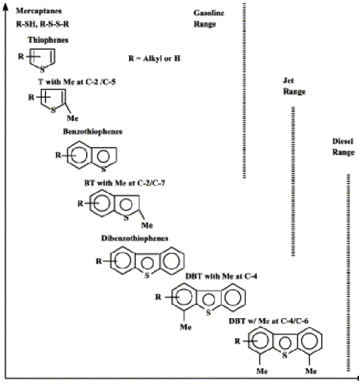
Figure 1.3 Reactivity of different organic sulfur compounds in HDS process versus their ring sizes and positions of alkyl substitutions on the ring..……….. 8
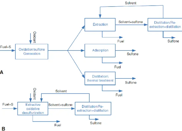
Figure 1.4 Representation of ODS systems; A) solvent-free CODS system and B) biphasic diesel/polar immiscible solvent ECODS system..……….. 10
Figure 1.5 Schematic representation of DBT oxidation..………. 10
Figure 1.6 Schematic representation of different POM structure..……… 13
Figure 1.7 Keggin structure: Mo or W = gray octahedra, heteroatom X = red, one (M3O13) unit = light blue with different types of oxygen shown as blue balls... 14
Figure 1.8 Representation of Keggin derivatives formation...……… 15
Figure 1.9 Several strategies to prepare POM-based catalysts..……….. 17
Figure 1.10 Different approaches to create functionalized mesoporous silica materials... 22
Figure 1.11 (a) structure of non-defective UiO-66 (UiO stands for University of Oslo) is comprised of [ZrO4(OH)4] clusters connected by terephthalate linkers. (b) Inclusion during framework synthesis of monocarboxylate modulators, can lead to correlated linker vacancies where a single terephthlate linker is replaced by two monocarboxylates in an opposing geometry..……….. 26
Figure 2.1 FT-IR spectra of the KPW11Zn and the hybrid zinc substituted polyoxometalates: [TBA]PW11Zn, [ODA]PW11Zn and [BMIM]PW11Zn………… 48
Figure 2.2 TGA curves of A) [TBA]PW11Zn, B) [ODA]PW11Zn and C) [BMIM]PW11Zn.…… 49
Figure 2.3 A) 31P NMR spectra of the KPW11Zn in D2O, [TBA]PW11Zn and the [BMIM]PW11Zn in CD3CN B) 31P MAS NMR spectra of [ODA]PW11Zn.………. 50
Figure 2.4 Kinetic profile, after the initial extraction step, for the oxidative catalytic stage of the desulfurization process using the model diesel (0.75 mL), catalyzed by different amounts of [TBA]PW11Zn catalyst, in the presence of MeCN as extraction solvent (0.75 mL) and H2O2 as oxidant (H2O2/S = 21), at 50ºC..….. 51
Figure 2.5 Desulfurization data obtained for each sulfur compound present in the model diesel after 4 h at 50ºC, in the presence of H2O2 as oxidant and catalyzed by different amounts of [TBA]PW11Zn………... 52
Figure 2.6 Desulfurization profile of a multicomponent model diesel in the present of MeCN as extraction solvent, at 50 ºC, catalyzed by [TBA]PW11Zn (9 µmol), using different amounts of oxidant H2O2..………... 53
Figure 2.7 Desulfurization profile of a multicomponent model diesel in the present of MeCN as extraction solvent, at 50 ºC and at room temperature, catalyzed by [TBA]PW11Zn (9 µmol) and using H2O2/S=21……….……….... 53
Figure 2.8 Profile of desulfurization of a multicomponent model diesel catalyzed by various hybrid PW11Zn based catalysts (9 µmol), in the present of MeCN as
extraction solvent, at 50 ºC and using 0.66 mmol of H2O2..………. 55
Figure 2.9 a) Image of the emulsion of [ODA]PW11Zn catalyst during the ECODS
process, dispersed between model diesel and MeCN extraction phase, b) at
the end of ECODS process after centrifugation (5000 rpm, 3 min)..……… 57
Figure 2.10 Desulfurization data for five consecutive ECODS cycles catalyzed by [TBA]PW11Zn (9 µmol), using a model diesel and MeCN as extraction solvent,
at 50 ºC and 0.66 mmol of the oxidant H2O2..……… 58
Figure 2.11 Recyclability for [ODA]PW11Zn catalyst (9 µmol) for desulfurization of a model
diesel in the presence of MeCN extraction solvent, at 50 ºC and H2O2 oxidant
(0.66 mmol)..……… 58
Figure 2.12 FT-IR spectra of [ODA]PW11Zn before (a) and after catalytic use for the
desulfurization of an untreated real diesel (b) and a model diesel after three
consecutive ECODS cycles (c)..……….. 59
Figure 3.1 FT-Raman spectra of (A) the PW12hybrids and (B) the trimethylammonium
-functionalized TMA-SBA-15 and the corresponding PW12@TMA-SBA-15
composite before and after catalysis (ac)..……….. 74
Figure 3.2 FT-IR spectra of (A) the PW12-hybrids and (B) the starting SBA-15 support,
the functionalized TMA-SBA-15 and the corresponding PW12@TMA-SBA-15
composite before and after catalysis..………. 75
Figure 3.3 Powder XRD patterns of trimethylammonium -functionalized SBA-15 (TMA-SBA-15) and the corresponding PW12@TMA-SBA-15 composite before and
after catalysis (abbreviated as ac)..………. 76
Figure 3.4 SEM images of the PW12@TMA-SBA-15 composite material at different
magnifications: (A) x5000, (B) x25000, (C) x60000 and (D) EDS spectrum... 76
Figure 3.5 Kinetic desulfurization profiles of the extractive and catalytic oxidative desulfurization (ECODS) process catalyzed by PW12, IL–PW12
compounds, composite material PW12@TMA-SBA-15 (3 µmol of PW12
active catalytic center) and blank experiments (without catalyst) using (A) [BMIM]PF6 and (B) MeCN as extraction solvents at 70 °C and H2O2/S
= 8..……….. 78
Figure 3.6 Kinetic desulfurization profiles catalyzed by [BPy]PW12 (3 µmol) for three
consecutive ECODS cycles using ionic liquid ([BMIM]PF6) as extraction
solvent at 70 °C and H2O2/S = 8..……… 80
Figure 3.7 Desulfurization data of multicomponent model diesel obtained after 1 h in the presence of the support (TMA–SBA-15), [BPy]PW12, PW12 and PW12
@TMA-SBA-15 (3µmol of active PW12) with MeCN or IL ([BMIM]PF6) as extraction
Figure 3.8 Kinetic profiles for the desulfurization of a multicomponent model diesel using the TMA-SBA-15 support using the ECODS model diesel/[BMIM]PF6 system
at 70 ºC and using H2O2/S = 8..………. 82
Figure 3.9 Kinetic desulfurization profiles of multicomponent model diesel catalyzed by PW12@TMA–SBA-15 for three continuous reused cycles using ionic liquid
([BMIM]PF6) as an extraction solvent at 70 °C and H2O2/S = 8..……… 82
Figure 3.10 SEM images of the PW12@TMA-SBA-15-ac material at different
magnifications: (A) x5000, (B) x25000, (C) x60000 and (D) EDS spectrum. ... 83 Figure 3.11 31P NMR spectra of [BPy]PW12 before and after catalytic use (ac) in the
presence of MeCN or IL extraction solvents. [BPy]PW12-ac-IL means after the
first ECODS cycle and [BPy]PW12-ac-IL-3 means after the third ECODS
cycle..……… 85
Figure 4.1 FT-IR (left) and FT-Raman (right) spectra of the isolated PW11 and the
composite materials PW11@aptesSBA-15 and PW11@tbaSBA-15..………….. 101
Figure 4.2 Solid state 31P MAS NMR spectra of the isolated PW11 and the composite
materials PW11@aptesSBA-15 and PW11@tbaSBA-15..………. 102
Figure 4.3 Solid-state 13C CP MAS (left) and 29Si MAS (right) NMR spectra of
PW11@aptesSBA-15 and PW11@tbaSBA-15..……….. 103
Figure 4.4 Powder XRD patterns of the support SBA-15 and composite materials
PW11@aptesSBA-15 and PW11@tbaSBA-15. ……….. 103
Figure 4.5 N2 adsorption-desorption isotherms of the support material SBA-15, the
functionalized aptesSBA-15 and the PW11@aptesSBA-15 composite. ……… 104
Figure 4.6 SEM images of (A,B) PW11@aptesSBA-15 and (C,D) PW11@tbaSBA-15
composite materials. EDS spectra of the PW11@aptesSBA-15 (E) and
PW11@tbaSBA-15 (F) composite materials..………. 105
Figure 4.7 Desulfurization profile of the multicomponent model diesel in the presence of different homogeneous catalysts, PW12, PW11 and PW11Zn (3 µmol), using
MeCN as extraction solvent and H2O2/S=8, at 70 °C..………. 108
Figure 4.8 31P NMR spectra of the homogeneous catalysts in the extraction phase
medium, after catalytic use (abbreviated as AC): PW12, PW11 and PW11Zn. ... 109
Figure 4.9 Desulfurization profile of the model diesel using the homogeneous PW11 and
the heterogeneous PW11@aptesSBA and PW11@tbaSBA catalysts
(containing 3 µmol of active PW11) using MeCN as extraction solvent and
H2O2/S=8, at 70 °C..………... 110
Figure 4.10 Desulfurization data of the various sulfur compounds present in the model diesel, using the homogeneous PW11 and heterogeneous PW11
@aptesSBA-15 and PW11@tbaSBA-15 catalysts (containing 3 µmol of active PW11) using
Figure 4.11 Kinetic profiles for the desulfurization of model diesel using the PW11@aptesSBA-15 catalyst (3 µmol of PW11) and the corresponding
leaching test., using H2O2/S = 8, at 70 °C..……… 111
Figure 4.12 Kinetic profiles for the desulfurization of a model diesel using the solvent-free or biphasic (model diesel/MeCN 1:1) systems with PW11@aptesSBA-15
composite (containing 3 µmol of PW11), using H2O2/S = 8, at 70 °C..………… 112
Figure 4.13 Kinetic desulfurization profiles of a multi-component model diesel using the solvent-free or biphasic (model diesel/MeCN 1:1) systems with the
homogeneous PW11 catalyst (3 µmol), using H2O2/S = 8, at 70 °C..………….. 113
Figure 4.14 Kinetic desulfurization profiles of a multi-component model diesel using a solvent-free system, catalyzed by different amounts of composite
PW11@aptesSBA-15 (1 and 3 µmol) and oxidant (H2O2/S = 2, 4, 8) at 70 °C. 113
Figure 4.15 Desulfurization of a multi-component model diesel using the biphasic (model diesel/MeCN 1:1) systems with the heterogeneous PW11@aptesSBA-15
catalyst (3 µmol of PW11), using H2O2/S = 4, at 70 °C..……… 114
Figure 4.16 Desulfurization results of a multicomponent model diesel after 1 h,performed for eight consecutive cycles, using the biphasic system diesel/MeCN (1:1) and
H2O2/S=8, catalyzed by PW11@aptesSBA-15 at 70 ºC..……….. 116
Figure 4.17 Oxidative desulfurization results obtained after 1 h for eight consecutive cycles using PW11@aptesSBA catalyst under a solvent-free system and H2O2/S=4 at
70 ºC..……….. 116
Figure 4.18 Powder XRD of the PW11@aptesSBA-15 composite before and after catalytic
use (ac) in a biphasic (model diesel/MeCN 1:1) system………….………. 117
Figure 4.19 FT-IR (left) and FT-Raman (right) of the PW11@aptesSBA-15 composite
before and after catalytic use (ac) in a biphasic (model diesel/MeCN 1:1)
system..……… 118
Figure 4.20 SEM images and EDS spectra of the PW11@aptesSBA-15 composite after
catalytic use in a biphasic (model diesel/MeCN 1:1) system..………. 120
Figure 4.21 31P MAS NMR spectra of the PW11@aptesSBA-15 composite before and after
catalytic use in a biphasic (model diesel/MeCN 1:1) system..………. 120
Figure 4.22 Desulfurization results of a real untreated diesel after 3 h, performed for three consecutive cycles, using the biphasic system (diesel/MeCN 1:1) and H2O2/S=8, catalyzed by PW11@aptesSBA-15 (containing 3 µmol of PW11), at
70 °C..………... 122
Figure 5.1 FT-IR (A) and FT-Raman (B) spectra of the SBA-15, the amine-functionalized aptesSBA-15, the isolated POMs and the PW12@aptesSBA-15 and
PW11Zn@aptesSBA-15 composites..……….. 138
Figure 5.2 Powder XRD patterns of the support SBA-15, the functionalized aptesSBA-15
Figure 5.3 31P MAS NMR spectra of the PW12@aptesSBA-15 and PW11
Zn@aptesSBA-15 composites..………... 140
Figure 5.4 Solid-state 13C CP MAS NMR spectrum of PW
11Zn@aptesSBA-15 (left) and 29Si MAS NMR spectra (right) of SBA-15, aptesSBA-15 and
PW11Zn@aptesSBA-15..……… 140
Figure 5.5 N2 adsorption-desorption isotherms of the support material SBA-15, the
functionalized aptesSBA-15 and the composite materials,
PW11Zn@aptesSBA-15 and PW12@aptesSBA-15. ………. 141
Figure 5.6 SEM images and EDS spectra of (A) PW11Zn@aptesSBA-15 and (B)
PW12@aptesSBA-15 composites..………... 142
Figure 5.7 Desulfurization of model diesel in the presence of different catalysts (3 µmol of active center) using the biphasic system (model diesel /MeCN 1:1, H2O2/S=8) and the solvent-free system (H2O2/S=4) at 70 ºC, after 60 min of
the oxidant addition..……….. 144
Figure 5.8 Kinetic profiles for the desulfurization of model diesel using the heterogeneous PW12@aptesSBA-15 and PW11Zn@aptesSBA-15 catalysts (containing 3
µmol of POM, using H2O2/S = 8 and at 70 ºC), and the corresponding leaching
tests (dotted lines) under the biphasic system..…... 145
Figure 5.9 31P NMR spectrum of the extraction MeCN phase at the end of the leaching
test using the PW12@aptesSBA-15 catalyst..………. 145
Figure 5.10 Desulfurization profiles of model diesel B catalyzed by PW11
Zn@aptesSBA-15 composite (containing 3 µmol of PW11Zn) using different oxidant amounts
under the (A) biphasic (model diesel/MeCN 1:1) and (B) solvent-free systems,
at 70 ºC..……… 146
Figure 5.11 Recycling desulfurization results using the PW11Zn@aptesSBA-15 composite
(containing 3 µmol of PW11Zn) after 60 min of the oxidant addition using the
solvent-free (H2O2/S=4) or biphasic (H2O2/S=8) systems at 70 ºC... 147
Figure 5.12 Desulfurization results for ten cycles, using the PW11Zn@aptesSBA-15
composite (containing 3 µmol of PW11Zn) after 60 min of the oxidant addition
using the solvent-free system (H2O2/S=4) at 70 ºC..………. 147
Figure 5.13 FT-IR spectra of the PW12@aptesSBA-15 and PW11Zn@aptesSBA-15
composites before and after catalytic use (ac is the abbreviation for after
catalysis)..……… 148
Figure 5.14 31P MAS NMR spectra of the PW12@aptesSBA-15 and PW11
Zn@aptesSBA-15 composites before and after catalytic use (ac stands for after catalysis)…. 149
Figure 5.15 Powder XRD patterns of the composites PW11Zn@aptesSBA-15 and
PW12@aptesSBA-15 before and after catalytic use (ac is the abbreviation for
Figure 5.16 SEM images and EDS spectra of (A) PW11Zn@aptesSBA-15 after ten cycles
under the solvent-free system and (B) PW12@aptesSBA-15 after one cycle
under the biphasic system..……….. 150
Figure 5.17 Desulfurization results obtained of untreated diesel for three ODS cycles 2 h after the oxidant addition, catalyzed by PW11Zn@aptesSBA-15 composite,
using the solvent-free (H2O2/S=8) or biphasic (H2O2/S=8) systems at 70 ºC... 151
Figure 6.1 - FT-IR (left) and FT-Raman (right) spectra of the isolated Eu(PW11)2, the
functionalized support aptesSBA-15 and the corresponding
Eu(PW11)2@aptesSBA-15 composite before and after catalysis (ac)….…….. 166
Figure 6.2 Powder XRD patterns of the starting SBA-15, the functionalized aptesSBA-15 and the Eu(PW11)2@aptesSBA-15 composite before and after catalysis
(ac)..……….. 167
Figure 6.3 Solid-state 13C CP MAS spectrum of Eu(PW11)2@aptesSBA-15..……….. 167
Figure 6.4 Left - Solid-state 31P MAS NMR spectra of the isolated Eu(PW11)2 and the
Eu(PW11)2@aptesSBA-15 composite before and after catalysis (ac). Right - 31P MAS NMR spectra of Eu(PW
11)2@aptesSBA-15 at different spinning
frequencies 5, 6 and 10 kHz. The isotropic chemical shifts are indicated with
an asterisk (*)..……… 168
Figure 6.5 29Si MAS (left) and CP MAS (right) NMR spectra of the functionalized SBA-15
and Eu(PW11)2@aptesSBA-15 composite..……… 169
Figure 6.6 SEM image, EDS and elemental mapping for the Eu(PW11)2@aptesSBA-15
composite..………... 170
Figure 6.7 Nitrogen adsorption-desoprtion isotherms at -196 °C of the mesoporous SBA-15, aptes-functionalized SBA-15 and the Eu(PW11)2@aptesSBA-15
composite. Filled and unfilled symbols represent the adsorption and
desorption processes, respectively..……… 171
Figure 6.8 Desulfurization of the multicomponent model diesel in a biphasic system (diesel/MeCN 1:1) showing the initial extraction stage (before the dashed line) and the catalytic stage (after the dashed line) in the presence of the homogeneous and heterogeneous catalysts (containing 3 µmol of Eu(PW11)2)
at 70 °C and using H2O2/S = 12..……… 173
Figure 6.9 Percentage of each sulfur component removed from the model diesel in the presence of the heterogeneous Eu(PW11)2@aptesSBA-15 catalyst
(containing 3 µmol of Eu(PW11)2)..………... 173
Figure 6.10 Kinetic profiles for the desulfurization of model diesel using the aptesSBA-15 support, blank experiment (without any catalyst), using H2O2/S = 12 and single
Figure 6.11 a) Results obtained for ten consecutive ECODS cycles after 2 h, using a multicomponent model diesel in the biphasic system catalyzed by Eu(PW11)2@aptesSBA-15 composite (containing 3 µmol of Eu(PW11)2). b)
Kinetic profiles for the desulfurization of the model diesel for the first three
ECODS cycles, using H2O2/S = 12 at 70 ºC..………. 175
Figure 6.12 Total sulfur oxidation of the multicomponent model diesel in the solvent-free system in the presence of the [TBA]Eu(PW11)2 and Eu(PW11)2@aptesSBA-15
catalysts (containing 3 µmol of Eu(PW11)2), using H2O2/S = 12 at 70 °C... 175
Figure 6.13 Percentage of each sulfur component removed from the model diesel in the presence of the heterogeneous Eu(PW11)2@aptesSBA-15 catalys (containing
3 µmol of Eu(PW11)2), using H2O2/S = 12 at 70 °C. in the solvent-free
system..………. 176
Figure 6.14 Kinetic profiles for the desulfurization of a model diesel using solvent-free or biphasic (diesel/MeCN) systems with Eu(PW11)2@aptesSBA-15 as catalyst
(containing 3 µmol of Eu(PW11)2), using H2O2/S = 12 at 70 °C..………. 177
Figure 6.15 Left - Results obtained for ten consecutive ODS cycles after 2 h catalyzed by Eu(PW11)2@aptesSBA-15 composite (containing 3 µmol Eu(PW11)2)under
solvent-free system. Right - Total oxidative desulfurization of the model diesel in the solvent-free system for the first three consecutive ODS cycles at 70 °C,
using H2O2/S = 12..………. 178
Figure 6.16 Sem image and EDS spectra of the Eu(PW11)2@aptesSBA-15 after catalytic
use..……….. 180
Figure 7.1 FT-IR spectra of the trimetylammonium-functionalized supports and the resulting PW11 composites (ac – after catalysis): (A) TMA-SBA-15 and
PW11@TMA-SBA-15 composite; (B) TMA-PMOE and PW11@TMA-PMOE;
(C) TMA-PMOB and PW11@TMA-PMOB..………. 195
Figure 7.2 FT-Raman spectra of the trimethylammonium-functionalized supports and the resulting PW11 composites: (left) TMA-SBA-15 and PW11@TMA-SBA-15
composite, (right) TMA-PMOE and PW11@TMA-PMOE..……… 196
Figure 7.3 SEM images of the trimetylammonium-functionalized supports and the resulting PW11 composites (A - TMA-SBA-15; B - PW11@TMA-SBA-15
composite; C - TMA-PMOE; D - PW11@TMA-PMOE; E - TMA-PMOB and F -
PW11@TMA-PMOB). EDS spectra of the PW11 composites..………. 196
Figure 7.4 Powder XRD patterns of the trimethylammonium-functionalized supports and the resulting PW11 composites (ac – after catalysis). (a) TMA-SBA-15 and
PW11@TMA-SBA-15 composite; (b) TMA-PMOE and PW11@TMA-PMOE; (c)
TMA-PMOB and PW11@TMA-PMOB..………... 198
Figure 7.5 N2 adsorption-desorption isotherms of the TMA-SBA-15 and PW11
Figure 7.6 31P MAS-NMR spectra of PW11 and PW11@TMA-SBA-15 and PW11
@TMA-PMOE composites………..……… 200
Figure 7.7 13C MAS NMR spectra of the trimethylammonium-functionalized supports and
the resulting PW11 composites. TMA-SBA-15 and PW11@TMA-SBA-15
composite (left); TMA-PMOE and PW11@TMA-PMOE (right)..……….. 201
Figure 7.8 29Si MAS spectra of the trimethylammonium-functionalized supports and the
resulting PW11 composites. TMA-SBA-15 and PW11@TMA-SBA-15
composite (left); TMA-PMOE and PW11@TMA-PMOE (right)..……….. 201
Figure 7.9 Desulfurization of each sulfur compound from the model diesel (left) and total oxidative desulfurization profile (right) using the biphasic system (1:1 model diesel/MeCN extraction solvent; ratio H2O2/S=8 at 70 ºC), using PW11
@TMA-SBA-15 and PW11@TMA-PMOE catalysts (containing 3 µmol of
PW11)..………... 203
Figure 7.10 Desulfurization of each sulfur compound in the multicomponent model diesel (left) and total oxidative desulfurization profile (right), using the solvent-free system (ratio H2O2/S=4 at 70ºC) and PW11@TMA-SBA-15 and PW11
@TMA-PMOE as catalysts (containing 3 µmol of PW11 active
center)..………. 204
Figure 7.11 Total conversion for sulfur oxidation presented in the model diesel, using the solvent-free system at 70ºC and PW11@TMA-SBA-15 catalyst (containing 3
µmol of of PW11), in the presence of two different H2O2/S ratios..……….. 204
Figure 7.12 Desulfurization results obtained for six catalytic cycles after 60 min of the oxidant addition, catalyzed by PW11@TMA-SBA-15 composite (containing 3
µmol of PW11), using the solvent-free (H2O2/S=4) and biphasic (H2O2/S=8)
systems, at 70 ºC..……….. 205
Figure 7.13 SEM images and EDS spectra of A - PW11@TMA-SBA-15 composite after
one cycle using the biphasic system; B - PW11@TMA-SBA-15 composite after
one cycle using the solvent-free system; C - PW11@TMA-SBA-15 composite
after eight cycles using the solvent-free system and D - PW11@TMA-PMOB
composite after catalytic use using the solvent-free
system..……….... 207
Figure 7.14 31P MAS NMR spectra of the PW11@TMA-SBA-15 composite (left) and
PW11@TMA-PMOE (right) before and after catalytic use (ac stands for after
catalysis)..……… 208
Figure 7.15 Desulfurization results of a real untreated diesel obtained after 2 h, catalyzed by PW11@TMA-SBA-15 at 70 °C, using the solvent-free system and the
Figure 8.1 – FT-IR spectra of the amine-functionalized supports and the resulting PW11Zn composites, before and after catalytic use (AC stands for after
catalysis): Left) aptesPMOE and PW11Zn@aptesPMOE; right) aptesPMOB
and PW11Zn@aptesPMOB..……….. 225
Figure 8.2 FT-RAMAN spectra of aptesPMOE and PW11Zn@aptesPMOE composite,
before and after catalytic use (left); aptesPMOB and PW11Zn@aptesPMOB
composite before and after catalytic use (right) (ac stands for after catalysis). 225 Figure 8.3 – Powder XRD patterns of the amine-functionalized supports and the resulting
PW11Zn composites (ac – after catalysis)..……….. 226
Figure 8.4 SEM images of the amine-functionalized PMOs and the resulting PW11Zn
composites (A - aptesPMOE; B - aptesPMOB; C - PW11Zn@aptesPMOE;
D - PW11Zn@aptesPMOB. EDS spectra of the PW11Zn composites..………... 227
Figure 8.5 N2 adsorption-desorption isotherms of the aptesPMOE support and
PW11Zn@aptesPMOE composite (left); aptesPMOB support and
PW11Zn@aptesPMOB composite (right)..……….. 227
Figure 8.6 31P MAS NMR spectra of PW11Zn and PW11Zn@aptesPMOE and
PW11Zn@aptesPMOB composites………...………... 228
Figure 8.7 13C MAS NMR spectra of the aptesPMOE support and PW11Zn@aptesPMOE
composite (left); aptesPMOB support and PW11Zn@aptesPMOB composite
(right)..……….. 230
Figure 8.8 29Si MAS NMR spectra of the amine-functionalized supports aptesPMOE and
aptesPMOB..……… 230
Figure 8.9 Desulfurization of each sulfur compound present in the model diesel (left) and kinetic desulfurization profile (right) using the biphasic ECODS system (1:1 model diesel/MeCN extraction solvent; ratio H2O2/S=8, at 70ºC) and 3 µmol
of PW11Zn active catalytic center present in PW11Zn@aptesPMOE and
PW11Zn@aptesPMOB..………. 231
Figure 8.10 Oxidative desulfurization of various sulfur compounds present in model diesel (left) and total oxidative desulfurization (right) using the solvent-free CODS system (ratio H2O2/S=4 at 70ºC), using as catalysts: PW11Zn@aptesPMOE
and PW11Zn@aptesPMOB, containing 3 µmol.of active PW11Zn
center..………... 232
Figure 8.11 Oxidative desulfurization results obtained for eight CODS cycles after 30 min and 60 min, catalyzed by PW11Zn@aptesPMOE composite (containing 3 µmol
of PW11Zn), using the solvent-free system and H2O2/S=4, at 70ºC..………….. 233
Figure 8.12 Oxidative desulfurization results obtained for ten CODS cycles after 60 min, catalyzed by PW11Zn@aptesPMOB composite (containing 3 µmol of PW11Zn)
using the solvent-free system and H2O2/S=4, at 70ºC..………... 234
Figure 8.13 SEM images and EDS spectra after catalytic use of A - PW11Zn@aptesPMOE
Figure 8.14 31P MAS spectra of the PW11Zn@aptesPMOE composite (left) and
PW11Zn@aptesPMOB (right) before and after catalytic use (AC – after
catalysis)..……… 237
Figure 8.15 Desulfurization results for the treatment of a real untreated diesel obtained after 2 h, performed for three consecutive ECODS cycles, catalyzed by
PW11Zn@aptesPMOE, at 70 °C and using H2O2/S=8..……… 237
Figure 9.1 FT-Raman spectra of the UiO-66 samples prepared by different synthetic
procedures..………. 252
Figure 9.2 Powder XRD patterns of the UiO-66 samples..………. 252
Figure 9.3 EDS spectra of the UiO-66 samples in the 1-5 keV range. All spectra are
normalized to the Zr L peak..……… 253
Figure 9.4 Kinetic profile for the desulfurization process of the model diesel using the different UiO-66 samples (9 µmol of Zr6O4(OH)4(CO2)12) at 50 ºC, showing the
initial extraction stage (before the dashed line) and the catalytic step (after the
dashed line)..……… 254
Figure 9.5 Catalytic profile for the desulfurization process of the model diesel using different amounts of the UiO-66 sample (amounts calculated for Zr6O4(OH)4(CO2)12 monomer) with acetonitrile as the extraction solvent. The
desulfurization process comprises two steps: the initial extraction stage
(before the dashed line) and the catalytic stage (after the dashed line)..…….. 256
Figure 9.6 Desulfurization of the multicomponent model diesel using UiO-66 (3 µmol of Zr6O4(OH)4(CO2)12) and the corresponding leaching test (catalyst removal
after 30 min of reaction)..………... 256
Figure 9.7 Desulfurization profile of a model diesel in the presence of UiO-66 (9 µmol of Zr6O4(OH)4(CO2)12), performing only the extraction liquid-liquid process, and
also combining extraction and catalytic steps in the presence of H2O2 oxidant.
A control experiment replacing the UiO-66 catalyst by ZrO2, using an
equivalent Zr content, combining extraction and catalytic steps..………... 257
Figure 9.8 Kinetic profiles for the desulfurization of the model diesel for three consecutive
cycles using the UiO-66 sample..………. 258
Figure 9.9 Percentage of each sulfur compound removed from the model diesel after the initial extraction step (darker part of the bars) and after 1 h (entire bares) of
the ECODS process for three consecutive cycles..……… 258
Figure 9.10 FT-IR (left) and FT-Raman (right) spectra of UiO-66 before and after catalytic
use (ac)..………... 259
Figure 9.11 Powder XRD patterns of UiO-66 before and after catalytic use (ac). ………… 260
Figure 9.12 SEM micrographs and EDS spectra of UiO-66 before (left) and after catalysis
(right)..……….. 260
Figure 9.14 SEM micrographs of UiO-66-NH2 (A) and SEM micrographs and EDS spectra
of PW11Zn@UiO-66-NH2 composite..………... 263
Figure 9.15 Powder XRD patterns of the UiO-66-NH2 and PW11Zn@UiO-66-NH2
composite..………... 263
Figure 9.16 Desulfurization of the multicomponent model diesel using H2O2/S=8 and 77
mg of UiO-66-NH2 and 77 mg PW11Zn@ UiO-66-NH2 composite (containing 3
µmol of active PW11Zn at 70ºC..……….. 264
Figure A.1 Chromatogram (GC-FPD) of untreated diesel (10 times diluted in ethyl
acetate)..……….. 284
Figure A.2 Chromatogram (GC-FPD) from the extraction MeCN phase presenting the no oxidized sulfur compounds extracted from untreated diesel, during 10 min at
50 ºC..……… 284
Figure A.3 Chromatogram (GC-FPD) of treated diesel (10 times diluted in ethyl acetate)
by oxidative catalytic desulfurization process..……….. 285
Figure A.4 Chromatogram (GC-FPD) from the extraction MeCN phase after the final
liquid extraction step performed to the diesel treated by ODS process..……... 285
Figure A.5 Chromatogram obtained by GC-FID/SCD from untreated diesel supplied by
CEPSA (A) and model diesel B (B)………..……… 286
Figure A.6 Chromatogram displays from the model diesel treated under solvent-free conditions Eu(PW11)2@aptesSBA-15 catalyst and H2O2 oxidant). (A) after 4 h
of catalytic sulfur oxidative reaction; (B) after 10 min of centrifugation treatment at room temperature; (C) after liquid-liquid extraction with 1 mL of acetonitrile; and (D) after three consecutive liquid extraction cycles with 1 mL
List of schemes
Scheme 2.1 Representation of the chemical structure of the used counter-cations..……… 47
Scheme 3.1 Ionic liquid cations used to prepare the hybrid PW12 catalysts..………. 73
Scheme 3.2 Representation of the preparation of the PW12@TMA-SBA-15 composite. …. 73
Scheme 4.1 Preparation route of the PW11@aptesSBA-15 and PW11@tbaSBA-15
composites..………. 100
Scheme 5.1 Representation of the preparation of POM based silica catalysts..……… 137
Scheme 6.1 Representation of the composite Eu(PW11)2@aptesSBA-15 preparation. …... 165
Scheme 7.1 Representation of the synthetic pathway for the different PW11-based
composites..………. 194
Scheme 8.1 Schematic representation of PW11Zn@aptesPMOE and
PW11Zn@aptesPMOB preparation..……… 223
Scheme 9.1 Schematic representation of the 3D framework of UiO-66 (top) and the
List of tables
Table 1.1 Crude oil constituents.……..………. 4
Table 1.2 Distribution of Sulfur compounds over the distillation range of a crude oil…… 6
Table 1.3 Experimental conditions and desulfurization efficiency for the various hybrid
POM-based catalysts applied in diesel desulfurization..……….. 20
Table 1.4 Experimental conditions and desulfurization efficiency for the various POM-based silica catalysts applied in diesel desulfurization presented in this
section..……… 24
Table 1.5 Metal organic frameworks applied in oxidative desulfurization processes….. 26
Table 1.6 Experimental conditions and desulfurization efficiency for the various MOFs
applied in diesel desulfurization presented in this section..………. 28
Table 1.7 Experimental conditions and desulfurization efficiency for the various POM-based metal-organic frameworks applied in diesel desulfurization presented
in this section..………. 30
Table 2.1 Desulfurization percentage of the various sulfur compounds present in the model diesel after 1 and 4 h of the ECODS process, catalyzed by different
hybrid catalysts at 50 ºC in the presence of MeCN as extraction solvent..…... 60
Table 2.2 Experiments performed for desulfurization of an untreated real diesel, using
MeCN as extraction solvent at 50 ºC..………. 57
Table 3.1 Individual and total desulfurization efficiency in the initial extraction (10 min) of the sulfur compounds from model diesel to the extraction phase (MeCN or IL) using TMA-SBA-15, [BPy]PW12 and PW12@TMA-SBA-15 as catalysts (3
µmol of PW12 active catalytic center)..………... 81
Table 4.1 Textural parameters of SBA-15 and the composite materials,
PW11@aptesSBA-15 and PW11@tbaSBA-15. ……….. 104
Table 4.2 Comparison of desulfurization efficiency and experimental conditions used, in the presence for various PW11 based catalysts applied in the desulfurization
of model diesel..………... 115
Table 4.3 Results of the experiments for desulfurization of untreated real diesel obtained
after 2 hours of oxidation using H2O2/S = 8, at 70 °C………….……….. 120
Table 5.1 Textural parameters of SBA-15, aptesSBA-15 and the composite materials,
PW12@aptesSBA-15 and PW11Zn@aptesSBA-15..………. 141
Table 6.1 Textural parameters of SBA-15, aptes-functionalized SBA-15 and
Eu(PW11)2@aptesSBA-15 composite..……… 171
Table 7.1 Textural parameters of the trimetylammonium-functionalized supports and the
resulting PW11 composites…….……… 199
Table 8.1 Textural parameters of the amine-functionalized supports and the resulting
Table 9.1 Cl/Zr atomic ratios determined via EDS spectra of the UiO-66 samples..……. 254
Table 10.1 The most efficient catalytic desulfurization systems based in prepared
composites to treat model diesels..……….. 278
Table 10.2 The most efficient catalytic desulfurization systems based in prepared
Abbreviations and symbols
1-BT 1-benzothiophene
4-MDBT 4-methyldibbenzothiophene 4,6-DMDBT 4,6-dimethyldibenzothiophene
5-MBT 5-methylbenzothipene
APDDAB 3-(acryloyamino)propyl]dodecyldimethyl ammonium API American Petroleum Institute
aptes (3-Aminopropyl)triethoxysilane BMIM 1-butyl-3-methylimidazolium
[BMIM]PF6 1-butyl-3-methylimidazolium hexafluorophosphate
BPMO bi(multi)-functionalized periodic mesoporous organosilica BPy 1-butylpyridinium
BTC 1,3,5-benzene-tricarboxylate BzPN benzyl aminiphosphazene
CHP cumenehydroperoxide
CODS Catalytic oxidative desulfurization DBT dibenzothiophene
DMF Dimethylformamide DMSO Dimethylsulfoxide
Dp Pore diameter
dw Wall thickness
ECODS Extractive catalytic oxidative desulfurization EDS Energy dispersive X-ray spectroscopy EtOH Ethanol
FT-IR Fourier transform infrared spectroscopy FT-RAMAN Fourier transform Raman spectroscopy
GC-FID Gas chromatography – flame ionization detector
GC-FID/SCD Gas chromatography – flame ionization detector /Sulfur Chemiluminescence Detector
GC-FPD Gas chromatography – flame photometric detector h Hours
HDPy Hexadecylpyridinium HDS Hydrodesulfurization
ICP-OES Inductively coupled plasma optical emission spectrometry IL Ionic liquid
HKUST Hong-Kong University of Science and Technology LDHs Layered double hydroxides
MCM-n Mobil composition of matter MeCN Acetonitrile
MIL Material of Institute Lavoisier min Minutes
MOF Metal organic framework MPS Methyl phenyl sulfide NENU Northeast Normal University
NMR Nuclear magnetic resonance ODA Trimetyloctadecylammonium ODS Oxidative desulfurization OMS Ordered mesoporous silica
PAM Poly(acrylamide) microgels PCPs Porous coordination polymers
PEG Polyethylene glycol
PMO Periodic mesoporous organosilica POM Polyoxometalate
PTA Phosphotungstic acid ppm Parts per million
SBA Santa Barbara Amorphous type material SBET BET (Brunauer–Emmett–Teller) surface area
SEM Scanning electron microscopy TBA Tetra-n-butylammonium
tba N-(3-trimethoxysilylpropyl)tributylammonium TBHP Tert-butyl hydroperoxide
TEOS Tetraethoxysilane
TGA Thermal gravimetric analysis Th Thiophene
TMA N-trimethoxysylilpropyl-N,N,N-trimethylammonium TMU Tarbiat Modares University
UiO University of Oslo
UMCM University of Michigan Crystalline Material Vp Total pore volume
wt% Weight percent
XRD Powder X-ray diffraction
ZIF Zeolitic Imidazolate Framework
Streching δ Bending
Chemical shift 2θ Diffraction angle
Chapter 1
Introduction
Chapter Index
1.1. Context………... 3
1.2. Crude oil and desulfurization demand……….. 3
1.3. Hydrodesulfurization……….. 7 1.4. Oxidative desulfurization (ODS)….……… 9 1.4.1. General description of ODS process………...…… 9 1.5. Polyoxometalates……… 12 1.5.1. Keggin anion……….. 13 1.5.1.1. Keggin derivatives………... 14 1.6. POM-based heterogeneous catalysts in ODS processes……… 16 1.6.1. Solidification of POMs with counter-cations………... 17 1.6.2. Immobilization of POMs in support materials………. 21 1.6.2.1. Ordered mesoporous silica……… 21 1.6.2.2. Periodic mesoporous organosilicas……….. 24 1.6.2.3. Metal-organic frameworks……….. 25 1.6.2.3.1. Metal-organic frameworks as catalysts……… 26 1.6.2.3.2. Metal-organic frameworks as supports……… 28 1.7. General plan……… 31 1.8. References……….. 32
Chapter 1
Introduction
1.1. Context
Sulfur compounds present in liquid fuels are responsible for the release of SO2 and
air borne particulate during combustion. Therefore, the desulfurization of fuels is crucial in the petroleum-processing industry. The current method implemented in refining industries, to remove sulfur compounds from crude oil, is hydrodesulfurization (HDS). This method operates under severe operation conditions using metal catalysts to convert sulfur compounds in H2S. Despite HDS process effectiveness, it reveals some vital flaws
such as the need of high pressures (20-100 atm of H2) and temperatures (300-400 ºC),
hydrogen consumption and reduction of octane/cetane number in fuels. Consequently, there is an urgent need for the development of more sustainable and economic desulfurization methods for the production of sulfur-free fuels. [1] An alternative method to HDS is oxidative desulfurization (ODS) that operates in two main steps: oxidation of sulfur compounds in sulfoxides and/or sulfones and their removal by extraction processes. ODS is considered to be an alternative or even a complementary method to the actual HDS, presenting several advantages such as mild operation conditions, low cost of energy and use of less expensive oxidants. [2] The success of ODS process is dependent on the presence of an efficient catalyst in the oxidative step. For a future success industrial application, it is important that the catalyst presents high efficiency and robustness, making possible its recyclability and continuous use in successive cycles. [2, 3]
1.2. Crude oil and desulfurization demand
Although the energy obtained from renewable sources has been increasing during the recent years, fossil fuels remain the larger fraction of energy source (still over 82%) around the world. Half of which is obtained from crude oil, with larger portions of petroleum being used in the transportation sector[4, 5]. Crude oil is a naturally complex mixture of hydrocarbons that can also contain organic compounds with sulfur, nitrogen, oxygen and metals (Table 1.1).
Oil refineries take the advantage of the different weights, volatilities and boiling temperatures of crude oil hydrocarbons in order to separate them and create intermediary and finished products (Figure 1.1). Several refinery streams are used to produce three major types of transportation fuels: gasoline, jet fuels and diesel that differ in composition and properties.
Table 1.1 - Crude oil constituents [6, 7]
Constituent Chemical type
Hydrocarbons: Paraffinic (Alkanes) Naphthenic
Aromatic
Straight chain; branched chain
Alkyl cyclopentanes; alkyl cyclohexanes
Alkyl benzenes; aromatic naphthenic fluorenes; polynuclear aromatics
Dissolved gases Nitrogen (N2); carbon dioxide (CO2)
Sulfur compounds Hydrogen sulfide (H2S)a, mercaptans; organic sulfides,
disulfides and polysulfides; thiophenes and benzothiophenes; sulfones Organic nitrogen compounds Pyridine, quinoline Organic oxygen compounds
Carboxylic acids (including naphthenic acids)b, alcohols,
phenolsb, aldehydes, ketones, esters, ethers, oxyacids
Organic metallic compounds
Porphyrins
Colloidal particles Asphaltenes; resins; paraffin waxes
Surfactants Sulfonic acids, sulfonates, sodium napthenates
Metals Vanadium, nickelc, ironc, aluminum, sodium, potassium,
calcium, copper Water (S&Wd or
BS&Wd)e
Fresh or saline
Solids Sand, dirt, silt, soil dust, mud, corrosion products (metals’ oxides,sulfides, salts)
aHydrogen sulfide is present as dissolved gas
b They are surfactants
c They are present in porphyrins
d S&W—sediment and water; as previously called BS&W—bottoms sediment and water e Microorganisms can be present in crude oils
Crude oil gravity (American Petroleum Institute – API) and sulfur content (sweet for low sulfur and sour for high sulfur) are the most important parameters that define crude oil quality and price. Sulfur content of crude oil and refinery streams is usually expressed in weight percent (wt%) or parts per million by weight (ppm). The average of sulfur content in crude oil varies from less than 0.1% to greater than 5% depending on its type and origin. Sulfur concentration in distillated crude oil tends to increase progressively with increasing carbon number and boiling range (Table 1.2). Therefore, crude fractions obtained in the boiling range of fuel oil and asphalt have higher sulfur content than those in the jet and diesel boiling range. On the other hand, these last have

![Table 1.2 - Distribution of Sulfur compounds over the distillation range of a crude oil [13, 14]](https://thumb-eu.123doks.com/thumbv2/123dok_br/18905629.935815/44.892.144.756.531.772/table-distribution-sulfur-compounds-distillation-range-crude-oil.webp)


![Figure 1.10 - Different approaches to create functionalized mesoporous silica materials [107]](https://thumb-eu.123doks.com/thumbv2/123dok_br/18905629.935815/60.892.248.662.108.532/figure-different-approaches-create-functionalized-mesoporous-silica-materials.webp)
![Figure 2.1 - FT-IR spectra of the KPW 11 Zn and the hybrid zinc substituted polyoxometalates: [TBA]PW 11 Zn, [ODA]PW 11 Zn and [BMIM]PW 11 Zn](https://thumb-eu.123doks.com/thumbv2/123dok_br/18905629.935815/86.892.318.633.561.960/figure-spectra-kpw-hybrid-zinc-substituted-polyoxometalates-bmim.webp)
![Figure 2.2 - TGA curves of A) [TBA]PW 11 Zn, B) [ODA]PW 11 Zn and C) [BMIM]PW 11 Zn](https://thumb-eu.123doks.com/thumbv2/123dok_br/18905629.935815/87.892.180.799.122.587/figure-tga-curves-tba-pw-zn-oda-bmim.webp)
![Figure 2.3 - A) 31 P NMR spectra of the KPW 11 Zn in D 2 O, [TBA]PW 11 Zn and the [BMIM]PW 11 Zn in CD 3 CN B) 31 P MAS NMR spectra of [ODA]PW 11 Zn](https://thumb-eu.123doks.com/thumbv2/123dok_br/18905629.935815/88.892.243.650.126.395/figure-nmr-spectra-kpw-tba-bmim-mas-spectra.webp)
