COMMON-REFLECTION-SURFACE ATTRIBUTES
Fernando Gamboa,
1Eduardo Filpo,
2Martin Tygel
3Recebido em 17 jan. ,2003 / Aceito em 28 jan., 2004 Received Jan. 17, 2003 / Accepted Jan. 28, 2004
ABSTRACT
Applied to multicoverage data, the Common-Reflection-Surface (CRS) method obtains, besides a clear stacked section, also a number of traveltime parameters or attributes defined at each point of that section. The CRS parameters provide useful information for a variety of seismic processing purposes. We consider the use of CRS attributes in multiple identification and attenuation. In the 2D situation, the CRS method produces three parameters associated with the resulting simulated (stacked) zero-offset (ZO) section. We propose and discuss simple algorithms designed to identify and, as a next stage, attenuate or eliminate multiples. First experiments show that these algorithms have the potential of favorably replace well-established multiple suppression methods.
Keywords: Multiples, Attenuation, CRS, Processing RESUMO
Aplicado aos dados multicovertura, o método da Superfície Comum de Reflexão (CRS) obtém uma seção empilhada mais limpa e um número de parâmetros do tempo de trânsito ou atributos definidos em cada ponto da seção. Os parâmetros do CRS proporcionam informação útil para uma variedade de processos sísmicos. Consideramos o uso de atributos do CRS na identificação e na atenuação de múltiplas. Na situação 2D, o método CRS fornece três parâmetros associados com a resultante (empilhada) seção de afastamento nulo (ZO). Apresentamos e discutimos um algoritmo simples desenhado para identificar e, num próximo estágio, atenuar ou eliminar múltiplas. As primeiras experiências mostram que estes algoritmos têm o potencial favorável de substituir os métodos de supressão existente. Palavras-chave: Múltiplas, Atenuação, CRS, Processamento
1 Universidade Estadual de Campinas UNICAMP. Instituto de Matemática, Estatística e Computação Científica IMECC. Departamento de Matemáticas Aplicada DMA. Praça Sergio Buarque de Holanda, 651 Cidade Universitária Barão Geraldo Caixa Postal: 6065 13083-859 Campinas, SP, Brasil +55.19.37885968 (Tel) - +55.19.32891466 (Fax) E-mail: [email protected]
2 Petróleo Brasileiro S.A. Petrobras. Av. Chile, 65, Sala 1402 Centro, Rio de Janeiro CEP 20031 912 Tel.: 55.21.2534 1967 Fax: 55.21.2534 4013 E-mail: [email protected] 3 UNICAMP IMECC. Praça Sergio Buarque de Holanda, 651 Cidade Universitária Barão Geraldo. Caixa Postal: 6065 Campinas São Paulo 13083-859 E-mail: [email protected]
INTRODUCTION
One of the main objectives of reflection seismics is to derive an image of the subsurface from multicoverage reflection seismic data. Stack-ing procedures, such as the conventional common midpoint (CMP) method, are thoroughly used, because of their ability to increase the energy of reflection signals, while attenuating coherent and random noise.
Stacking means summing seismic amplitudes along suitable traveltime curves or surfaces that are able to constructively interfere in the case of reflection or diffraction events, as opposed to other signals, such as noise, where they destructively interfere. The traveltime curves or surfaces are either provided by the user (under the use of a priori given velocity models) or derived from the input multicoverage data (by means of a direct application of coherence analysis methods).
In this work, we consider the construction of a 2D simulated zero-offset (ZO) section. The traces of that ZO section, generally referred here as central points are usually taken to coincide with CMP locations. In the CRS method, the stacking surfaces are designed to stack reflec-tions from all source-receiver pairs around each central point. As op-posed to the CMP method that uses the normal-moveout (NMO) traveltimes, the CRS stacking curves makes use of all source-receiver pairs, arbitrarily located around the central point. Moreover, the stack-ing operation is performed at each central point and also at each time sample of the ZO to be simulated.
One of the main benefits of the CRS method is the full use of the available data, leading to a significantly better signal-to-noise ratio, that makes it easier the identification of reflection events, both prima-ries and multiples. Another very important benefit of the CRS method is the extraction of the CRS parameters (three attributes in the present situation) that provide important information on the reflection event (primary or multiple) under consideration.
A clean ZO section, together with appropriate CRS stacking pa-rameters, is the base of meaningful seismic processing procedures. Here we focus on the particular case of multiple identification and suppres-sion. As a result of the stacking procedure, primaries and multiples be-come more pronounced. In many cases, multiples can be easily identi-fied in the stacked section. Under the use of their associated CRS pa-rameters, these multiples can readily be attenuated or suppressed in the original multicoverage data, allowing for better further imaging pro-cedures such as migration. In other cases, the distinction between pri-maries and multiples are more difficult. In these cases, an analysis of the CRS parameters can be of help in the identification procedure, that
will lead, again, to attenuation or suppression of the multiple in a next stage. In this work we present algorithms designed for each of the above situations.
THEORY
The normal-moveout (NMO) method is a routine processing step designed to produce a simulated zero-offset (ZO) section by means of a stacking procedure performed on CMP gathers that relate to user-se-lected reflection events. As an important part of procedure, an NMO-velocity map on the simulated (stacked) ZO section is also obtained.
The NMO method is based in the following requirements: (a) the stacking operation is performed on CMP gathers only; (b) the stack-ing is performed over a few user-selected reflection events and a few CMPs only and (c) for each selected event, a corresponding NMO-veloc-ity is estimated by means of a (one-parameter) coherence analysis car-ried out at the CMP gather that refer to this event. The full NMO-velocity map results from suitable interpolation (in time and CMP location) of the few, previously obtained NMO-velocities. For a general description and also practical considerations on the NMO method, the reader is referred to Yilmaz (2000) (see also more references therein).
NMO-traveltime
We consider the 2D situation, in which the given seismic dataset stem from sources and receivers located on a single horizontal seismic line and propagation occurs on the vertical plane below that line. Upon the consideration of a given CMP location,
x
0, and a ZO traveltime,0
t
, the coherence analysis and stacking operation are carried out usingthe NMO-traveltime formula
( )
2 2 2 2 4 NMO h t h tυ υ = + . (1)As a function of half offset, h, the above NMO-traveltime, t(h), represents (second-order hyperbolic approximation of) the traveltime along the reflection ray that connects the source-receiver pair,
(
x0−h x, 0+h)
, in the CMP gather of x0. Finally, υMNOrepre-sents the NMO-velocity.
In recent years, the above-described requirements of the NMO method, namely its restriction to CMP data, user-selected events and extraction of a single attribute (the NMO-velocity) from the data, began to be questioned by the geophysical community. As a response to these limitations, more general approaches to the problems of stacking and
extraction of traveltime parameters from multicoverage data have been proposed. In the seismic literature, the new approaches are referred to as macro-model-independent or time-driven imaging methods. The Com-mon-Reflection-Surface (CRS) method, as used in this work, is one of them. For a general description of macro-model-independent methods, the reader is referred to Hubral (1999).
CRS-traveltime
The common feature of the new approaches is the use of general traveltime moveouts that are able to stack traveltimes of source-receiver pairs that belong to much larger gathers, namely ones that do not con-form to the original CMP condition. Traveltime moveouts that meet the new requirements are known for a long time. The CRS Method uses a natural extension of the NMO traveltime (1), the general hyperbolic traveltime. It is valid for arbitrary locations of source and receivers in the vicinity of a given ZO point, in most cases a CMP location. In the case of a horizontal seismic line, if the ZO point is located at
x
0 along theseismic line and if υ0 is the medium velocity at that point, the hyper-bolic traveltime formula can be written as
( )
(
)
2 2 0 0 0 2sin m t h t β x x υ = + − + (
)
2 2 2 0 0 0 2 cos m N NIP x x t h R R β υ − + + . (2)Here, β denotes the angle the ZO ray makes with the vertical at
0
x
and and are the radii of curvature of the N-wave and NIP-wave,respectively. Comparison of the NMO and hyperbolic traveltimes (1) and (2) provides 2 0 2 0 2 cos NIP NMO R t υ υ β = . (3)
As introduced in Hubral (1983), the (normal) N-wave is the one that starts with the shape of the reflector in the vicinity of the reflection point of the normal ray that starts and ends at x0 at the seismic line,
and travels upwards with half the velocity of the medium until it is observed, also at x0. In the same way, the (normal-incidence-point)
NIP-wave is the one that starts as a point source at the reflection point of the normal ray to x0 and travels upwards with half the velocity of
the medium until it is observed at x0. We also observe that the
reflec-tion point of a normal ray on a reflector is called normal-incidence-point (NIP).
THE CRS TRAVELTIME ATTRIBUTES
The hyperbolic traveltime (2) depends on three attributes
(
β,RN,RNIP)
, called CRS parameters, defined for each ZO loca-tion, x0 and traveltime, t0. For a grid of preassigned points(
x t0,0)
,and assuming that the near-surface velocity, ν0 is known at each x0,
the CRS method produces the parameter maps,β β=
(
x t0, 0)
,(
0, 0)
u = u x t and RNIP=RNip
(
x t0,0)
, as well as acorre-sponding simulated (stacked) ZO section u=u x t
(
0, 0)
. As we see,in the same way as the NMO method, one of the results of the CRS method is also a (simulated) ZO section. However, as opposed to the NMO method that produces one single parameter estimated from a CMP gather, the CRS method produces a triplet of parameters estimated from the multicoverage gather.
Multiple Reflections
A multiple reflection can be defined as a seismic event that suf-fered more than one ascending reflection. A first classification of multi-ples can be stated as free-surface and internal multimulti-ples. A free-surface multiple is a typical event in marine data, namely a reverberation be-tween the ocean floor and the free surface of the water. An internal multiple occurs within internal subsurface layers. The order of a free-surface multiple is defined as the number of reflections it has experi-enced at the free surface. In contrast, the order of a internal multiple is defined by the total number of downward reflections (WEGLEIN et al., 1997). Currently, multiple-attenuation methods are divided into two main groups, namely (a) filtering and (b) prediction/subtraction. The first approach (filtering) exploits the different characteristics (e.g., traveltime, frequency) between primaries and multiples, trying to iden-tify and eliminate the multiples by means of some filtering procedure. In this category, we cite the FK, Radon and slant-stack method as widely used schemes (YILMAZ, 2000). The second approach (prediction/sub-traction) tries to simulate the multiple to be suppressed, either from an a priori given model or from attributes directly derived from the seismic data. Well-known examples of that group include the inverse-scattering series and predictive deconvolution (WEGLEIN et al., 1997) and Yilmaz (2000). The above-mentioned two approaches can also be combined. An example of such an approach is provided in Landa and others (1999). Multiples can also be attenuated by simple stacking operations. For instance, after NMO-correction using primary velocities, multiples can be naturally attenuated as a consequence of inadequate NMO-cor-rection. Such an approach will be pursued below in the framework of the CRS stacking method.
MULTIPLE IDENTIFICATION USING CRS PARAMETERS
In the following, we consider that, for a given multicoverage dataset, the CRS method has already been applied. As a consequence, both the CRS parameter maps, as well as the CRS stacked section are available. We then consider the use of the obtained CRS parameters for the purpose of multiple attenuation. Before we describe our strategies, it is useful to recall some of the main characteristics of the CRS method-ology.
Basic remarks on the CRS method
A. The general hyperbolic moveout gives rise to three parameters,
(
β,RNIP,RN)
, as opposite to the single-parameter, νNMO,obtained by the CMP method. The three parameters allows for a better identification or discrimination of a (primary or multiple) reflection event. Note, moreover, that the simple relationship (3) determines the NMO-velocity by means of the two parameters β and RNIP. For
a illustrative layered model containing primaries and multiples, Figure 1 displays three panels, showing the behavior of the CRS parameters β , RNIP, as well as the NMO-velocity, νNMO, obtained
by the combination of the two previous parameters.
B. As opposed to the CMP method, in which the NMO-velocity is estimated on a few user-selected events only and further interpolated at all the other points, the CRS method automatically estimates the parameters
(
β,RNIP,RN)
, at every point at the simulated ZO section. The CRS method is, thus, bound to yield more detailed and precise velocity maps.1 Due to the involved interpolations, the NMO method will in many case provide velocities that are incorrect for primaries and correct for multiples (see Figure 2).C. When the CRS parameters along a multiple are well identified, that multiple can be modelled and eliminated in any (pre-stack) domain. This is due to the fact that the hyperbolic equation (2) well adjusts, not only to the CMP, but to any measurement configuration gather. Moreover, in the case the amplitude of a primary is altered by the simultaneous arrival of a multiple, the correct amplitude of the primary can be recovered using the amplitudes of traces of nearby CMPs (see Figure 5).
CRS PARAMETERS OF PRIMARIES AND MULTIPLES
Useful insight for the geometrical meaning of the CRS param-eters can be gained by the consideration of a single reflector in a homo-geneous medium. In this simplest situation, we see that the CRS pa-rameters, β, and (roughly) inform us about the reflectors dip, depth
and shape, respectively. We use this very qualitative observation to guide us on how to use the CRS attributes to identify or discriminate multiple and primaries. For example, if we have at point
(
x t0,0)
on theCRS-stacked section a very large RN
(
RN ? 1)
and a very smallβ (β » 0), we can associate it with a planar, horizontal reflector. As a second example, suppose for the same trace location, x0, we have two
events at traveltimes ( )1 ( )2
0 0
t <t for which the corresponding
param-eters satisfy ( )1 ( )2
NIP NIP
R >R . This would indicate that the second event
would be a multiple.
This situation is well illustrated in the marine-data synthetic example of Figure 1. The depth model (not shown in the figure) con-sists of four curved interfaces, A, B, C and D, below the sea surface, denoted by S. The primaries of all interfaces are denoted Ap, Bp. Cp and Dp, respectively. The events Am1 and Am2 are first- and second-order (surface) multiples of first interface A. Also, CAm is the first-order mul-tiple, SCSAS, of interface C with respect to the water surface S. Finally, CBCm represents the internal multiple, SCBCS, that starts at S, reflects at C, reflects at B, reflects at C and returns to S.
Looking at the events Ap, Am1 and Am2, we can readily verify their periodicity and almost constant increment of the values RNIP and
β. This, in turn, leads to very close NMO-velocity values for these events, in agreement with the expected behavior as free-surface multiples (see next section). We now note that the RNIP values of the multiples Am2
and CAm are significantly smaller than the RNIP values of the
previ-ously identified primaries. In both cases, we observe the combination of an increasing arrival time together with a decreasing value of RNIP,
an expected behavior of a multiple. We finally consider the multiple CBCm. Although their CRS parameters RNIP and β do not present any
particular behavior, the NMO-velocity (as obtained by the combination of these parameters) is smaller than the NMO-velocity of the primary Cp, also a characteristic behavior of a multiple.
PREDICTION OF MULTIPLE REFLECTIONS
In this section we consider some fundamental cases for which multiples can analytically expressed by means of the CRS attributes. These cases will serve as a guide for future procedures in more general situations.
FREE-SURFACE MULTIPLES FOR A DIPPING SEA
BOTTOM
We consider the typical marine situation of free-surface multiple reflections from the sea bottom. As shown by Levin (1971), for a planar
1 The NMO velocities obtained at all time samples by the CRS method represent, in fact, stacking velocities that need later to be smoothed, so as to be inverted for interval velocities. In this respect, see Perroud, Tygel and Bergler (2002) and Perroud and Tygel (2003).
Figure 1 CRS attributes for primaries and multiples on a ZO section: (a) CRS stack section with primaries Ap, Bp, Cp e Dp and multiples Am1, Am2, CAm e CBCm; (b) Coherency maps for RNIP for the trace CMP300 of section (a); (c) Coherency map for β for the trace CMP=300 of section (a) and (d) Coherency map
for the NMO velocity, as obtained from RNIP and β, for the trace CMP=300 of section (a).
Figura 1 ` Atributos do CRS para primárias e múltiplas em uma seção ZO: (a) Seção empilhada pelo CRS com as primárias Ap, Bp, Cp e Dp e as múltiplas Am1, Am2, CAm e CBCm; (b) Mapa da coerência para RNIP para o traço CMP=300 da seção (a); (c) Mapa da coerência para β para o traço CMP=300 da
seção (a) e (d) Mapa da coerência para a velocidade NMO, obtida do RNIP e β, para o traço CMP=300 da seção (a).
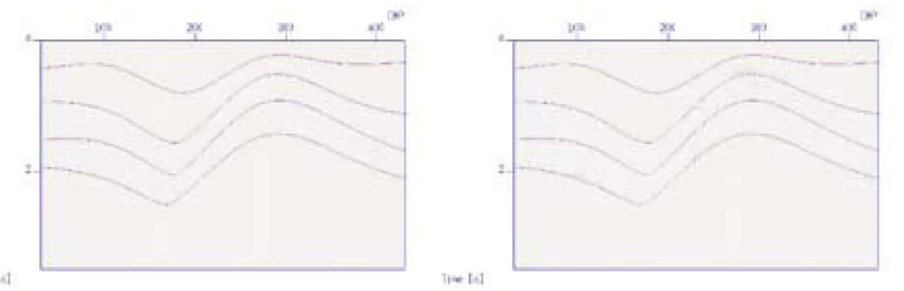
Figure 2 Left: Simulated stacked section with primaries and multiples; Right: NMO stacked section using primary-reflection velocities. Note that, even though multiples are not flattened by the NMO-velocity analysis, they are nevertheless also stacked.
Figura 2 ` Esquerda: Seção empilhada com primárias e múltiplas; Direita: Seção empilhada NMO usando velocidades das reflexões primárias. Note-se que, mesmo que as múltiplas não sejam aplainados pela análise de velocidades NMO, são também empilhados.
dipping sea bottom and a CMP gather, the traveltime of a primary re-flection can be written as
( )
2 2 2 0, 2 , 4 p p NMO p h t h t υ = + , (4)where t0, p is the ZO traveltime of the primary at the CMP location and
υNMO,p is its NMO-velocity. Note that, in the present situation, the CRS emergence angle and NIP-wave curvature parameters, β and
, 0 0,
, and / 2
p RNIP p t p
β =α =υ , (5)
in which α is the reflectors dip, and υ0 is the medium (water)
veloc-ity. For the same CMP gather, the traveltime of any multiple of the previous primary has an analogous expression
( )
2 2 2 0, 2 , 4 m m NMO m h t h t υ = + , (6)in which t0,m and υNMO m, have analogous meanings of their
primary-reflection counterparts. Let us assume that
(
βm,RNIP m,)
rep-resent the CRS emergence angle and NIP-curvature parameters for the multiple. Denoting by N the order of the surface multiple, one can
0, 0, , , cos sin , , sin cos p m m p NMO m NMO p p m t β t υ β υ β β = =
(
)
, sin 1 , . sin m m p NIP m NIPp p N R β R β β β = + =INTERNAL MULTIPLES IN HORIZONTALLY
LAYERED MEDIA
In the case of a model of horizontal homogeneous layers (β = 0 for all interfaces), the NIP-curvature parameter of a primary reflection at the N-th interface, RNIP p, , can be expressed as (HUBRAL;
KREY, 1980) 2 , 0 0 1 N N NIP p i i i R υ t υ = =
∑
. (7)We consider a symmetrical multiple (HUBRAL; KREY, 1980) be-tween interfaces N and n, ( n<N ) that corresponds to the previous primary. To compute its NIP-parameter, RNIP m, , we have to take into
account the extra propagation between the interfaces n and N. From simple geometrical arguments, we can show that
, 2 , , 0 1 N N n N NIP m NIP p j j j n R R υt υ = = +
∑
. (8)With the knowledge of , ,
N n NIP m
R and also taking into account
that β = 0, we can determine the NMO-velocity of the symmetric multiple by 2 0 , , 0 2 N n NMO RNIP m t υ υ = . (9)
It is to be noted that, in the case of dipping planar interfaces, analogous expressions ,
,
N n NIP m
R and can be readily obtained. These
depend, however, also on the reflector dips and will not be shown here.
METHODS FOR MULTIPLE ATTENUATION
OR ELIMINATION
Based on the considerations made in the last section, we pro-ceed to describe our proposed methods for multiple elimination using the CRS attributes. As explained earlier we assume that these attributes are already available from a previous application of the CRS method.
CRS stacking using primary-reflection parameters
The method consists of performing the CRS stacking using the CRS parameters that pertain to previously-identified primaries only. As a consequence, we obtain a stacked section with those primaries only. An application of this procedure is shown in Figure 3.
Elimination of a multiple by modelling
Multiples can also be eliminated by means of a process that consists of a few steps, as depicted in the flowchart of Figure 4. The key steps in the above multiple-suppression algorithm are:
Identification of multiples: The CRS parameters of a multiple can be obtained (a) by a priori knowledge or direct inspection on the CRS-stacked section or (b) as a suitable use of parameter relationships, such as the above-derived formulas for the specific cases of free-surface or internal symmetrical multiples.
Traveltime extrapolation: If the three parameters of a multiple are known (e.g., using the methodology as in Figure 1), its moveout, in any configuration, is well described by hyperbolic equation (2). This allows a more precise traveltime determination of the multiple and, as a consequence, a better discrimination from concurrent events. Modelling of multiples: After the traveltime of the multiple is well
determined, an estimation of the source wavelet and an adjustment with the amplitudes in the data can be carried out by means of a suitably designed shaping filter. Se do not enter here in the details of the construction of that filter. We remark, nevertheless, that such filters constitute a well-known part of many modelling schemes. As a result, the multiple is modelled. Having obtained the modelled multiples, we can next produce a dataset having multiples only or subtract the multiples from the multicoverage data, producing a dataset with primaries only.
Figure 3 Left: Simulated ZO section; Right: CRS stacked section obtained using parameters of primaries only. Note the good attenuation of the multiples. Figura 3 ` Esquerda: Seção simulada ZO; Direita: Seção empilhada CRS obtida usando somente os parâmetros das primárias.
Note-se a boa atenuação das múltiplas.
Results of the multiple elimination method using the automatic approach are shown in Figure 5.
Extension for inhomogeneous layered
media with curved interfaces
In the case of a general model with inhomogeneous layers and curved interfaces, the modelling and suppression of a multiple can be performed in an analogous manner as before. As it is often the case in geophysics, a full theoretical analysis is carried out on simple models (homogeneous layers separated by planar horizontal or dipping inter-faces) only. Although derived under simplifying assumptions, it is rea-sonable to expect that the obtained expressions still provide useful ini-tial approximations in some optimization scheme. The actual validity of the multiple-suppression schemes proposed here is still a topic of ongo-ing investigation.
MULTIPLE ELIMINATION IN THE COMMON-SHOT
DOMAIN
A very interesting and promising multiple elimination method has been proposed by E. Landa and co-workers (LANDA; KEYDAR; BELFER, 1999) in the framework of the Multifocus method. Similar to the CRS method, the Multifocus method uses a different traveltime moveout for-mula, that also depends on the the same three parameters β, RNIP
and RN. For a description of the Multifocus method, and moreover to its
relationship to the CRS and other imaging methods, the reader is re-ferred to Hubral (1999). In Landa, Keydar and Belfer (1999), it is shown that the traveltime of each multiple can be decomposed as a sum of
traveltimes of a number of primaries. The CRS (or Multifocus) param-eters of each of these primaries are seen to satisfy a so-called multiple condition (namely a relationship between the emergence angles of the primary components of the multiple). The procedure is carried out in the common-shot or common-receiver domains and, in the same way as the proposed methods in this paper, does not require any knowledge of the subsurface velocity model.
CONCLUSIONS
The CRS method offers a good alternative to treat a number of seismic processing tasks. This can be explained by the consistent use of the full available data and also the automatic extraction of several pa-rameters that are related to the involved seismic propagation. In the 2-D situation considered here, the CRS method depends on three param-eters that need to be inverted from the full multicoverage. This is to be contrasted to the single-parameter, NMO-velocity, involved in the con-ventional CMP method. In this paper, we have discussed the use of the CRS parameters, as obtained from the application of the CRS method, to identify and eliminate multiples. We have considered two situations, namely (a) the elimination of a multiple that has been already identi-fied in the CRS stacked section and (b) the identification and elimina-tion of a multiple by means of a suitable behavior of its CRS parameters. Our investigation of the latter case was restricted to the particular cases of free-surface multiples and symmetrical internal multiples. In these simple and initial situations, our results have shown to be very encour-aging. More realistic applications are achieved by means of suitable approximations. This we intend to do in future work.
Figure 4 The method considered for the multiple attenuation by modelling, using CRS parameters, involves: (a) Identification of multiples, (b) modelling of multiple in any domain and adjust the amplitudes, and (c) subtraction of multiples.
Figura 4 ` O método considerado para a atenuação de múltiplas por modelando, usando os parâmetros do CRS, envolve: (a) Identificação das múltiplas, (b) modelamento das múltiplas em algum domínio e ajuste das amplitudes, e (c) subtração das múltiplas.
Figure 5 Left: ZO section containing primaries and multiples; Right: ZO section after removal of first and second order free-surface multiple by modelling. Figura 5 ` Esquerda: Seção ZO que contem primárias e múltiplas; Direita: Seção ZO após a remoção das múltiplas de primeira e
segunda ordem da superfície livre por modelagem.
Acknowledgments
This work was partially supported by the Research Foundation of the State of São Paulo (FAPESP-Brazil), grant 01/01068-0, the Na-tional Council for Scientific and Technological Development
(CNPq-Bra-zil), grant 300927/82-7 and the National Petroleum Agency (ANP-Brazil) and by the sponsors of the Wave Inversion Technology (WIT) Consor-tium. All algorithms developed in this work use the Seismic Unix (SU) software, release 35.3, provided by the Center for Wave Phenomena, Colorado School of Mines.
REFERENCES
HUBRAL, P. Computing true amplitude reflections in a laterally inhomo-geneous earth. Geophysics, Tulsa, v. 48, n. 08, p. 10511062, 1983. ______. Macro-model independent seismic reflection imaging. J. Appl. Geophysics, Tulsa, v. 42, n. 3/4, 1999.
______; KREY, T. Interval velocities from seismic reflection time meas-urements. Society of Exploration Geophysicists, Tulsa, v. 1, 1980. LANDA, E.; BELFER, I.; KEYDAR, S. Multiple attenuation in the parabolic
domain using wavefront characteristics of multiple generating primaries. Geophysics, Tulsa, v. 64, n. 6, p. 18061815, 1999. ______; KEYDAR, S.; AND BELFER, I. Multiple prediction and at-tenuation using wavefront characteristics of multiple-generating prima-ries. The Leading Edge, Tulsa. v. 18, n. 1, p. 6064, 1999.
LEVIN, F. K. Apparent velocity from dipping interface reflections. Geo-physics, Tulsa, v. 36, n. 3, p. 510516, 1971.
PERROUD, H.; TYGEL, M. Nonstretch nmo. Presented of the VII Annual Report Wave Inversion Technology (WIT) Consortium, Karlsruhe, 2003. ______, ______; BERGLER, S. Velocity estimation by the CRS method: A GPR real data example. Trabalho apresentado no VI WIT Annual Report, Karlsruhe, 2002. p. 7291.
WEGLEIN, A. B. et al. An inverse-scattering series method for attenuat-ing multiples in seismic reflection data. Geophysics, Tulsa, v. 62, n. 6, p. 1975-1989, 1997.
YILMAZ, O. Seismic dta aalysis. Society of Exploration Geophysicists, Tulsa, v. 1, 2000.