1 INTRODUCTION
Recent seismic events induced severe damage to non-ductile reinforced concrete (RC) buildings prov-ing that many constructions located in seismic zones are unable to withstand moderate to severe earth-quakes.
Framed systems are extensively used for building structures in earthquake-prone regions because of their potential for good seismic performance. How-ever, many existing RC structures worldwide were designed for gravity loads only, having therefore in-adequate lateral load stiffness and resistance. The assessment and retrofitting of these structures is, thus, urgent.
Global intervention methods may represent a more cost-effective strategy than upgrading of the existing components, especially if the disruption of occupancy and the demolition and replacement of partitions, architectural finishes and other non-structural components are considered (Fardis 1998). This is particularly true for structures where no hori-zontal load path is available, or in the case of all
structural members being extremely flexible. In such cases the methods described above may result in an efficient solution (Pinho 2000).
Traditionally, steel bracing systems have been used to increase the lateral load stiffness/resistance of steel structures. In the past two decades, a number of reports have also indicated the effective use of steel bracing in RC frames (e.g., Youssef et al. 2007, Badoux & Jirsa 1990). Steel bracing of RC buildings started as a retrofitting measure to strengthen earth-quake damaged buildings or to increase the load re-sisting capacity of existing buildings (Maheri et al. 2003).
Increased architectural flexibility, reduced weight of the structure, easy and speed of construction and the ability to choose more ductile systems can be considered as the main advantages of steel bracing in comparison with strengthening based on the in-clusion of RC shear walls (Maheri & Ghaffarzadeh 2008).
Despite the several experimental and analytical studies conducted in the last years aiming to under-stand the behaviour of this type of hybrid structures (Maheri & Sahebi 1997, Badoux & Jirsa 1990), the fact is that only a few have resulted in the proposal
Seismic design of RC frames retrofitted with concentric steel braces
R. Sousa
European Centre for Training and Research in Earthquake Engineering (EUCENTRE), Pavia, Italy
J.M. Castro
Faculty of Engineering, University of Porto, Portugal
ABSTRACT: The implementation in Europe of a new seismic design code (Eurocode 8) will impose strict performance requirements to building structures. This will result in a significant number of existing rein-forced concrete structures showing inadequate seismic resistance and hence requiring intervention. One of the available retrofitting techniques consists of inserting steel braces in the original RC structure. In spite of the advantages of using this retrofitting approach, the adoption of this technique is still limited due to the lack of seismic design rules. The interaction between the steel braces and the RC members turns the design in an in-tricate task. The main goal of the research presented in this paper was to develop a simple yet reliable design procedure that can promote the retrofitting of reinforced concrete frames with steel braces. The proposed method is based on displacements and accounts for the interaction of the steel elements on the deformation capacity of the RC members. To this end, nonlinear static and time-history analysis of reinforced concrete structures strengthened with concentric steel braces have been performed with the objective of deriving a number of key parameters (displacement profiles, yield drifts and target displacements) which are essential for the application of the new design procedure. The paper closes with an application of the proposed method to a RC structure with inadequate seismic resistance. The performance assessment of the retrofitted structure, carried out with nonlinear static analysis, confirms the validity of the design procedure and demonstrates the merits of adopting displacement-based seismic design approaches.
of values for the so call behaviour factor to be used in the design process. Moreover, due to the scatter of results, the values obtained in past works do not provide enough confidence to achieve an effective solution.
The aim of the present work is thus to develop a displacement-based design (DBD) procedure for the seismic retrofitting of RC frames with steel braces that overcomes the limitations with traditional force-based design (FBD) procedures. The methodology to be proposed should be simple and easy to apply by the designer, but should produce reliable structural solutions. Moreover, it should take into account the complex interaction between the steel braces and the RC elements.
2 SEISMIC BEHAVIOUR OF HYBRID SYSTEMS
2.1 Design approaches
Despite the potential for good seismic behaviour of steel braced RC frames, there is still a lack of design rules for hybrid structures in seismic codes. In order to overcome this situation, several studies (e.g. Maheri & Akbari 2003, Queirós 2009) were con-ducted with the objective of deriving values of the behaviour factor (q), also known as response modi-fication factor (R), to be adopted in FBD method-ologies.
However, due to the changes in the global struc-tural behaviour introduced by the steel braces, the improvement of the seismic behaviour may not be, for certain types of braces, proportional to the in-crease of lateral strength of the structure.
Moreover, the values of q proposed by different researchers are not entirely consistent due to the relatively complex interaction between the RC members and steel braces. For this reason, it be-comes apparent that the seismic design of this type of structures should be carried out focusing on de-formation rather on strength control.
Di Sarno & Manfredi (2009) stated that the new bracing system should be designed to absorb and dissipate large amounts of hysteretic energy under earthquake ground motion, at the same time that the original RC system should be capable to withstand the vertical loads and respond elastically under the earthquakes loads. In the present study, however, for economical and structural reasons, it is considered that the original RC system should still be allowed to undergo inelastic deformations.
2.2 Interaction between the steel braces and the RC frame
Several studies demonstrated that the lateral stiffness and strength of a hybrid steel braced RC frame re-sults from the contribution of the two lateral resist-ing systems workresist-ing independently (Badoux & Jirsa 1990, Di Sarno & Manfredi 2009).
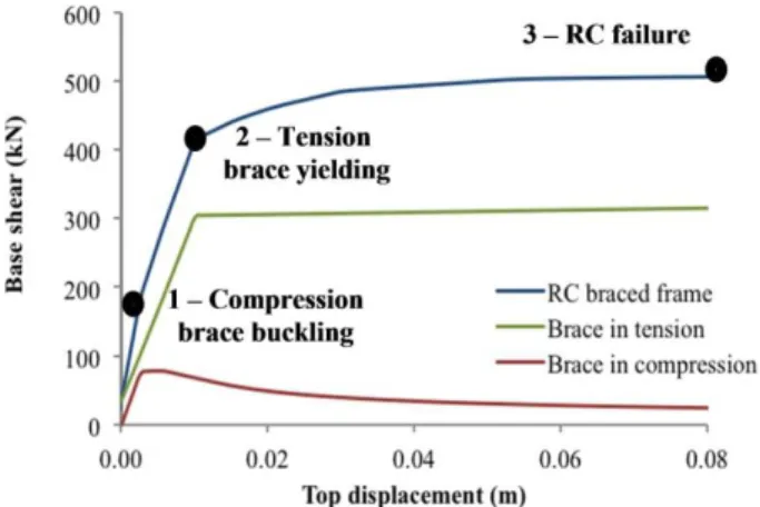
A typical pushover curve of a RC structure retro-fitted with concentrically steel slender braces is il-lustrated in Figure 1 (Queirós 2009). As expected, the onset on nonlinear behaviour of the hybrid struc-ture corresponds to the occurrence of buckling in the first storey brace. However, due to the relatively low contribution of the compressive braces to the lateral resistance, particularly in cases where slender braces are adopted, it is possible to confirm from Figure 1 that the global yield displacement of the structure occurs when the first storey brace yields in tension.
Figure 1. Identification of yield displacement on steel braced RC frames (adapted from Queirós 2009).
Della Corte & Mazzolani (2008) demonstrated that, for cases with stockier braces, the transition from buckling to ultimate state is not as smooth as that illustrated in Figure 1.
With regard to the behaviour of the RC members of the retrofitted structure, Sousa (2010) concluded that the column axial load at the base of the structure can be well estimated by adding the axial load in the original structure with that resulting from the verti-cal components of the braces assuming that, over the height of the structure, all tensile braces are in the yield state.
Despite the increases of stiffness and strength re-sulting from the introduction of braces, it is impor-tant to note that the increase in brace capacity leads to an increase of the axial forces in the columns. This effect results in a reduction of the column’s de-formation capacity and hence, it is possible that a given solution adopted for the braces may lead to premature failure of the RC columns. Thus, since the ultimate displacement of the structure is typically governed by column deformation capacity, it is of critical importance that the design method used in the retrofitting process is able to relate the brace ca-pacity with the deformation caca-pacity of the RC col-umns.
2.3 Lateral displacement profiles
The lateral deformation profile is an important pa-rameter to use in design/assessment procedures rely-ing on equivalent linearization.
Previous analytical studies on hybrid RC-steel structures (e.g., Pincheira & Jirsa 1995) showed that the displacement shapes of this type of structures were relatively uniform and that the storey drifts varied smoothly over the height of the buildings.
Several authors proposed expressions to describe the lateral deformation of building structures (e.g. Priestley et al. 2007). However, most of those ex-pressions have been proposed for RC structures and are generally dependent only on the number of floors.
In a recent numerical study, Sousa (2010) ana-lysed the behaviour of a 1-bay 3-storey RC frame designed for gravity loads according to the current European design provisions for RC structures (CEN 2004). The structure was retrofitted with steel braces with two different values of normalised slenderness (λ = 2.0 and λ = 3.0). The retrofitted frames were analysed in the nonlinear finite element software OpenSEES (PEER 2006) under the action of eight earthquake records selected from the PEER NGA database (PEER 2009). For consistency, the ground motions for the analysis had mean period (Tm) val-ues between 0.5 and 0.6s, representative of an inter-mediate group proposed in the work of Kumar et al. (2010). The deformed shape of the two frames was obtained for two different deformation levels: i) first ‘yielding’, corresponding to the buckling of the compressive brace located at the first storey, ii) in-cipient failure of the structure, corresponding to the attainment of the maximum deformation capacity of the most critical RC column in the structural system.
The results obtained were compared with existing expressions for RC structures (Priestley et al. 2007). It was observed that the use of steel braces imposes a higher control of the displacements over the height of the building. Consequently a new expression has been proposed, as follows:
= × × 1 − . × (1)
Where is the lateral displacement of the i-th floor,
Hi is the height of the floor and Hn it the total height
of the structure. It must be emphasized that the ex-pression was validated only with the results obtained for the two frames considered in the study and hence there is a need to conduct additional analysis with different braces (layout and/or strength) and for taller systems.
3 PROPOSAL OF A DESIGN METHOD FOR STEEL BRACED RC FRAMES
3.1 Basis of the method
It has been demonstrated that the introduction of steel braces in a RC structure leads to the modifica-tion of the behaviour of the original RC system, namely in terms of lateral strength and deformation capacity. Thus, a strategy based on the equivalent linearization approach adopted by the Capacity Spectrum Method (Freeman 1998) appears to be a rational approach for the proposed methodology.
The main idea behind the proposed method is the estimation (without any structural analyses) of the performance of the structure retrofitted with differ-ent brace properties or bracing layout.
The main objective of the method is to find the most optimal bracing solution that ensures that the deformation demand imposed on the structure does not lead to failure of the most critical RC element. Focusing on Figure 2 it can be observed that the ad-dition of steel braces, despite modifying the global behaviour of the structure, does not always provide a suitable retrofitting solution. Consequently, in order to define a bracing solution that ensures a given per-formance level, several brace properties and/or lay-out need to be evaluated.
Figure 2. Graphical interpretation of the proposed design methodology based on the Capacity Spectrum Method.
Based on the capacity curve of the original RC structure and on a set of different brace properties and bracing layout, and by employing the proposed methodology, the designer can accurately estimate the performance of the structure (pairs of ultimate displacements-base shear values) without the need to perform several numerical analyses for different bracing configurations.
3.2 Description of the method
The proposed method comprised the seven steps de-scribed below:
1. Nonlinear static (or pushover) analysis of the RC structure to obtain the capacity curve. 2. Pre-selection of steel brace properties and
installed in the RC columns at the ultimate limit state. The selection is carried out such that the predicted additional axial load to-gether with the static axial load does not lead to premature column failure.
3. Estimation of the yield displacement (∆y)
us-ing the followus-ing expression:
∆ = + ×× − ℎ − (2)
Where is the initial length of the diagonal brace, Nt is the brace tensile capacity, E is the
Young modulus, A is the cross-sectional area of the steel brace, h is the storey height and b is the bay length. Further details on the deri-vation of the above expression can be found in Sousa (2010).
4. Determination of the ultimate displacement (∆u) of the structure. This step is performed
as-suming that the ultimate displacement is gov-erned by the attainment of the maximum de-formation capacity of the most critical RC member, typically a base column. For this purpose, an estimate of the additional axial load in the column imposed by the braces (for all combinations of braces and layout) is re-quired. As mentioned before, it is acceptable to assume that at ultimate limit state all the braces reached yield in all the bays over the height of the structure. The ultimate displace-ment is obtained by calculating the chord rota-tion capacity of the RC elements based on the calculated values of axial load. With the chord rotation capacity of the critical element, the column drift can be conservatively estimated as being equal to its chord rotation capacity (Mpampatsikos et al. 2008). Note that if shear capacity is limited, additional strengthening, other that steel bracing needs to be considered. 5. Estimation of the lateral strength (Vb) of the
hybrid structure as the summation of the base shear of the original RC frame, corresponding to the ultimate displacement calculated in the previous step, with the horizontal component of the tensile capacity of the braces located at the first storey. In this step, the capacity de-veloped by the braces in compression is con-servatively neglected.
6. Evaluation of the equivalent viscous damping (EVD) based on the estimated ductility calcu-lated with the yield and ultimate displacements obtained in steps 3 and 4. It must be pointed out that there is not a specific expression available for steel braced RC frames. In this work, and for the sake of simplicity, an ex-pression proposed by Priestley et al. (2007) for RC frames will be adopted:
! = 0.05 + 0.565 × %×(%&'
(3)
7. Selection of the most suitable retrofitting solu-tion. This final step requires the conversion of the base shear (Vb), yield and ultimate
dis-placements in parameters of an equivalent SDOF system. This is carried out with the aid of the expression proposed before for the lat-eral displacement profile. Following that, the damping spectra based on the ductility of each bracing solution consideration is also obtained. All the data is then plotted in the format of an acceleration-displacement response spectrum (ADRS). From this plot, points representing ultimate displacements and corresponding base shears are identified for each retrofitting solution. The acceptability of each bracing so-lution can be evaluated through comparison of the location of each point in relation to the as-sociated damping spectrum.
4 VALIDATION OF THE PROPOSED METHOD
4.1 Structure characterization and seismic scenario
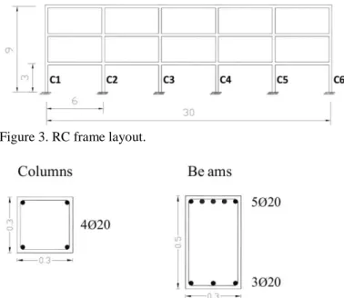
The accuracy of the method will be evaluated through an application to a typical RC building re-quiring seismic retrofitting. The building considered is a 3-storey, 5-bays RC structure with 4m spacing between frames. The structure represents a building with inadequate seismic resistance in which the ele-ments were only designed for gravity loads accord-ing to Eurocode 1 (CEN 2002) and Eurocode 2 (CEN 2004). The dead load considered was 9 kN/m2 whilst the imposed load was assumed as 5 kN/m2. The elevation view of one of the RC moment frames is shown in Figure 3. The cross-sections adopted for the beams and columns are illustrated in Figure 4.
Figure 3. RC frame layout.
In order to assess the seismic performance of the original RC structure, it is fundamental to define the seismic hazard scenario for the site in which the structure is located. For the purpose of this study the seismic action prescribed in Eurocode 8 (CEN 2004) is considered. The elastic response spectrum adopted is that proposed for seismic action Type 1. More-over, it is assumed that the structure is founded on a soil of type B according to EC8 and that the refer-ence peak ground acceleration (ag) is taken as 1.3m/s2.
4.2 Seismic assessment
For the sake of simplicity, the assessment of the original RC structure is carried out by applying the Capacity Spectrum Method (CSM). As shown in Figure 5, the bilinear curve does not intersect the re-sponse spectrum for the corresponding equivalent viscous damping compatible with the ductility ca-pacity of the structure. This means that a perform-ance point cannot be determined and hence that the structure is not able to resist the design earthquake.
Figure 5. Seismic assessment applying the CSM.
4.3 Design of the retrofitting solution
In order to retrofit the structure, three different brac-ing layouts with constant brace properties over the height of the building are considered (Figure 6).
Figure 6. Three bracing configurations (Solutions 1, 2 and 3).
Moreover, five different brace properties were se-lected and tested for each bracing layout illustrated in the previous figure. The main properties of the steel braces are presented in Table 1.
Table 1 - Properties of the selected steel braces Brace ID Outside diameter Thickness Sectional area Slenderness D (mm) t (mm) A (cm2) -̅ Brace 1 76.1 3.2 7.3 3.0 Brace 2 88.9 3.6 9.6 2.6 Brace 3 114.3 3.2 11.2 2.0 Brace 4 139.7 3.2 13.7 1.6 Brace 5 139.7 5.0 21.2 1.7
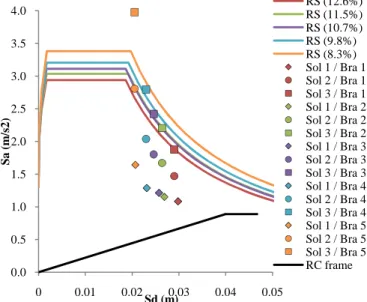
In order to evaluate if any of the solutions satis-fies the seismic requirements, the estimated points corresponding to the ultimate limit state of the hy-brid structure are superimposed to the corresponding damped response spectra (Figure 7). It should be noted that, for simplicity, and because the damping values for each steel brace are very similar, only the spectrum with the lowest value of damping is plot-ted. The colours and marks represent the different bracing elements and layout solutions, respectively. Finally, in order to evaluate the differences in struc-tural behaviour of the retrofitted solutions with re-spect to the original RC frame, a bilinear representa-tion of the capacity curve of the original structure is also represented.
It must be recalled that the solutions representing a good seismic behaviour are the ones in which the points are outside the area of the corresponding damped response spectra. Although the points do not correspond to performance points for the limit state under consideration, their position outside the damped spectrum, ensures the existence of a per-formance point in an earlier stage.
Figure 7. Evaluation of the performance of the different retro-fitting solutions.
From Figure 7 it is possible to conclude that only Solution 3 (three braced bays) provides an effective
0.0 0.5 1.0 1.5 2.0 2.5 3.0 3.5 4.0 0 0.01 0.02 0.03 0.04 0.05 S a ( m /s 2 ) Sd (m) RS (12.6%) RS (11.5%) RS (10.7%) RS (9.8%) RS (8.3%) Sol 1 / Bra 1 Sol 2 / Bra 1 Sol 3 / Bra 1 Sol 1 / Bra 2 Sol 2 / Bra 2 Sol 3 / Bra 2 Sol 1 / Bra 3 Sol 2 / Bra 3 Sol 3 / Bra 3 Sol 1 / Bra 4 Sol 2 / Bra 4 Sol 3 / Bra 4 Sol 1 / Bra 5 Sol 2 / Bra 5 Sol 3 / Bra 5 RC frame
seismic retrofitting for the structure under analysis. From the possible solutions, the use of steel braces other that “Braces 5” is more economical but it is close to the limit of an acceptable seismic perform-ance. On the other hand, if the objective is to de-velop a solution that mitigates damage, then Solu-tion 3 with “Braces 5” appears to be more advisable.
4.4 Accuracy of the method
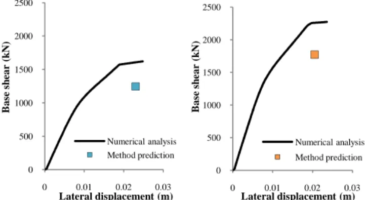
A pushover analysis of the retrofitted frame (Solu-tion 3 with “Braces 4” and “Braces 5”) was per-formed in order to investigate if the proposed design method produced a reliable structural solution. The results from the pushover analysis along with the representation of the performance point are pre-sented in Figure 8.
Figure 8. Comparison of the method predictions with a push-over analysis – Solution 3 with “Braces 4” (left) and “Braces 5” (right).
The results confirm that the ultimate points esti-mated using the proposed method are consistent with the global behaviour of the structure observed in the pushover analysis.
The observed differences are a result of approxi-mations assumed in the design process, namely with respect to the actual load installed in the steel braces. Thus, the lower value of the estimated base shear is a result of neglecting the component of the braces in compression which, in cases of stocky braces, can be relevant. Moreover, the eventual increase in the flexural moment capacity of the RC columns due to the higher level of axial load, with the consequent increase of the base shear, was also neglected. Fi-nally, the lower values obtained for the lateral de-formation capacity are the result of assuming that all steel braces, both in compression and tension, were at full capacity in all storeys. This assumption re-sulted in a conservative (upper) estimate of the axial load installed on the RC columns leading to a reduc-tion in their de-formareduc-tion capacity.
It should be mentioned that the limitations dis-cussed above could be overcome if the axial loads developed in the braces were evaluated in a more ac-curate away. For a given ultimate displacement, the lateral frame deformation of the hybrid structure could have been estimated for each storey based on the expression proposed for the lateral displacement
profile. With the relative displacement of each sto-rey, the brace axial load could be assessed and hence a more accurate estimate of the axial loads installed in the columns. Nevertheless, the adoption of such an iterative strategy will lead to an additional effort that, based on the accuracy of the results obtained, may not be justifiable.
5 CONCLUSIONS
This paper focused on the seismic retrofitting of RC frames with steel braces. Previous analytical and ex-perimental studies indicated that the application of steel braces in RC frames might significantly im-prove the performance of RC buildings with inade-quate seismic behaviour. In some applications this technique may be more advantageous in comparison with other retrofitting approaches.
One of the main factors that limit the application of this retrofitting technique is the limited design guidance provided by the current seismic codes. In the present work the behaviour of hybrid structures has been analysed in detail. The knowledge ac-quired, combined with the recent developments in seismic design, namely the Direct Displacement-Based Design method proposed by Priestley et al. (2007), resulted in the proposal of a design approach for the retrofitting of regular RC frames with steel braces. The proposed method is simple, intuitive and easy to use in practical applications. In order to sim-plify the process, some approximations have been made without jeopardizing the required accuracy in-herent to the structural design.
It must be emphasized that despite the proposed method being applicable to any RC moment frame, due to the lack of displacement profiles for taller buildings at this moment its use is recommended only for low-rise structures.
Another issue that can be expected regarding high-rise buildings is related with the predictable development of high levels of axial load in the col-umns at the lower storeys. To avoid this potential problem, the proposed retrofitting technique can be combined with other types of interventions avail-able for strengthening RC elements (e.g., the use of FRP). On the other hand, since the seismic loads are concentrated at the base of the building and de-crease over the height, the retrofitting solution can be optimized by changing the brace strength based on the expected seismic demand.
REFERENCES
Badoux, M. & Jirsa, J. O. 1990. Steel bracing of RC frames for seismic retrofitting. Journal of Structural Engineering 116(1):55-74. 0 500 1000 1500 2000 2500 0 0.01 0.02 0.03 B as e sh ear ( k N ) Lateral displacement (m) Numerical analysis Method prediction 0 500 1000 1500 2000 2500 0 0.01 0.02 0.03 B as e sh ear ( k N ) Lateral displacement (m) Numerical analysis Method prediction
Della Corte, G. & Mazzolani, F.M. 2008. Theoretical devel-opments and numerical verification of a displacement-based design procedure for steel braced structures. 14th
World Conference on Earthquake Engineering, Beijing,
China.
Di Sarno, L. & Manfredi, G. 2009. Design approach for the seismic strengthening of an existing RC building with buckling restrained braces. STESSA 2009 – Seismic
Be-haviour of Steel Structures in Seismic Areas,
Philadel-phia, PA.
Di Sarno, L. & Manfredi, G. 2009. Experimental tests on full scale RC frames retrofitted with buckling restrained braces; STESSA 2009 – Seismic Behaviour of Steel
Struc-tures in Seismic Areas, Philadelphia, PA.
CEN 2002. EN 1991-1-1, Eurocode 1: Actions on Structures: Part 1-1: General actions – Densities, self-weight, im-posed loads for buildings. European Committee for Stan-dardization, Brussels.
CEN 2004. EN 1992-1-1, Eurocode 2: Design of concrete structures – Part 1-1: General rules and rules for build-ings. European Committee for Standardization, Brussels. CEN 2004. EN 1998–1, Eurocode 8: Design provisions for
earthquake resistance of structures. Part 1: General rules, seismic actions and rules for buildings. European Com-mittee for Standardization, Brussels.
Fardis, M.N. 1998. Seismic assessment and retrofit of RC structures. Proceedings of the Eleventh European
Confer-ence on Earthquake Engineering, Paris, France.
Freeman, S.A. 1998. The Capacity Spectrum Method as a Tool for Seismic Design. 11th European Conference on
Earthquake Engineering, Paris, France.
Kumar, M., Castro, J.M., Elghazouli, A.Y. & Stafford, P.J. 2011. Influence of mean period of ground motion on the dynamic response of single and multi degree of freedom systems. Earthquake Engineering and Structural
Dynam-ics 40: 237-256.
Maheri, M.R. & Sahebi, A. 1997. Use of steel bracing in re-inforced concrete frames. Engineering Structures 19(12): 1018-1024.
Maheri, M.R., Kousari, R. & Razazan, M. 2003. Pushover tests on steel X-braced and knee-braced RC frames.
En-gineering Structures 25: 1697–1705.
Maheri, M.R. & Akbari, R. 2003. Seismic behaviour factor, R, for steel X-braced and knee-braced RC buildings.
En-gineering Structures 25: 1505-1513.
Maheri, M.R. & Ghaffarzadeh, H. 2008. Connection over-strength in steel-braced RC frames. Engineering
Struc-tures 30: 1938-1948.
Mpampatsikos, V., Nascimbene, R., & Petrini, L. 2008. A critical review of the RC frame existing building assess-ment procedure according to Eurocode 8 and Italian Seismic Code. Journal of Earthquake Engineering 12(S1): 52–82.
PEER 2006. OpenSees: Open System for Earthquake Engi-neering Simulation. Pacific Earthquake EngiEngi-neering
Re-search Center, University of California, Berkeley, CA.
PEER 2009. NGA Database. Pacific Earthquake Engineering
Research Center, University of California, Berkeley, CA.
Pincheira, J.A. & Jirsa, J.O. 1995. Seismic response of RC frames retrofitted with steel braces or walls. Journal of
Structural Engineering 121(8): 1225-1235.
Pinho, R. 2000. Selective Retrofitting of RC Structures in Seismic Areas. PhD thesis, Imperial College London, London, UK.
Priestley, M. J. N., Calvi, G. M. & Kowalsky, M. J. 2007. Displacement-Based Seismic Design of Structures; IUSS
Press. Pavia, Italy.
Queirós N.T. 2009. Seismic analysis and design of hybrid steel-concrete structures. MSc thesis, Faculty of
Engineer-ing of the University of Porto, Portugal. (in Portuguese)
Sousa R. 2010. A Displacement-Based Design approach for seismic retrofitting of RC frames with steel braces. MSc
thesis, ROSE School, Pavia, Italy.
Yousef, M. A., Ghaffarzadeh, H., Nehdi, M. 2007. Seismic performance of RC frames with concentric internal steel bracing. Engineering Structures 29: 1561-1568.