INTRODUCTION
Since the panoramic technique was discovered by Paatero in 1952, dentists in a variety of dental specialties have used panoramic radiography imaging, in spite of the new techniques that have emerged on the market. Panoramic radiography is a simple method of obtaining images by synchronous rotation of the x-ray source and image receptor around the stationary patient. However, there is a magnifying factor associated with image formation, due to the distance between the radiation source, object and image receptor, which can produce image distortion (1).
As is the case in the tomographic method (2), only anatomical areas of the patient’s head positioned within the image layer will appear with sharpness on the radiograph (1,3). Anatomical structures medially or
Evaluation of the Panoramic Image Formation
in Different Anatomic Positions
Daniela Brait Silva LADEIRA1 Adriana Dibo da CRUZ2 Solange Maria de ALMEIDA1
Frab Norberto BÓSCOLO1
1Department of Oral Diagnosis, Piracicaba Dental School, University of Campinas, Piracicaba, SP, Brazil 2Department of Specific Formation, Area of Radiology, Nova Friburgo Dental School,
Fluminense Federal University, Nova Friburgo, RJ, Brazil
The aim of this study was to determine size, shape and position of the image layer by evaluation of the radiographic image formation in different anatomic positions. A customized phantom was made of a rectangular acrylic plate measuring 14 cm² and 0.3 cm thick, with holes spaced 0.5 cm away and arranged in rows and columns. Each column was separately filled with 0.315 cm diameter metal spheres to acquire panoramic radiographs using the Orthopantomograph OP 100 unit. The customized phantom was placed on the mental support of the device, with its top surface kept parallel to the horizontal plane, and was radiographed at three different heights from the horizontal plane, i.e., the orbital, occlusal and mandibular symphysis levels. The images of the spheres were measured using a digital caliper to locate the image layer. The recorded data were analyzed statistically by the Student’s-t test, ANOVA and Tukey’s test
(α=0.05). When the image size of spheres in horizontal and vertical axes were compared, statistically significant differences (p<0.05)
were observed in all areas, portions of the image layer and heights of horizontal plane evaluated. In the middle portion of the image
layer, differences in the image size of spheres were observed only along the horizontal axis (p<0.05), whereas no differences were
observed along the vertical axis (p>0.05). The methodology used in this determined the precise size, shape and position of the image layer and differences in magnification were observed in both the horizontal and vertical axes.
Key Words: radiography, orthopantomography, radiographic magnification, diagnostic imaging.
laterally away from the image layer appear blurred and distorted in the radiograph (4,5) with changes in size or shape (6). Thus, radiographic image formation is directly affected by the shape of the image layer, which varies among different panoramic x-rays units (7).
The image layer has a curved shape, and is three-dimensional, constituted of three different portions: middle, inner and outer. In the middle portion, magnification factors for vertical and horizontal axes of the image are similar, while in the inner and outer portions they are dissimilar, mainly due to magnification of the horizontal axis responsible for causing the image distortion (8). Thus, considering that panoramic radiographic image quality is dependent on the image layer, which differs from one panoramic x-ray machine to another, the aim of this study was to determine the size, shape and position of the image layer by evaluating the
radiographic image formation in each anatomic position.
MATERIAL AND METHODS
To determine the image layer, a customized phantom was made using a 0.3-cm-thick rectangular acrylic plate with an area of 14 cm² and holes in the top surface spaced at every 0.5 cm and arranged in rows and columns. The holes were made using a cylindrical drill #1 mounted in a low-speed handpiece in a column drill press with mobile table. The top surface was divided into four quadrants with an equal number of lines and columns. Metal spheres measuring 0.315 cm in diameter were inserted in the holes, filling each column of a specific quadrant at a time, to acquire the panoramic radiographic images.
Panoramic radiographic images were acquired using the Orthopantomograph® OP 100 panoramic unit (Instrumentarium Imaging, Tuusula, Finland), with a high-frequency unit, focal size 0.5 x 0.5 mm, total filtration to 3.2 mm of aluminum, exposure time ranging from 2.7 to 17.6 s. For panoramic radiographic image formation, the magnification factor, reported by the machine manufacturer, is constant at 1.3. The x-ray tube was operated at 57 kVp, 3.2 mA, and exposure time of 17.6 s.
The metal cassette was used with Lanex® regular screen and T-Mat G x-ray film (Eastman Kodak Company, São José dos Campos, SP, Brazil). After radiographic exposure all films were processed in an automatic processor Macrotec MX-2 (Macrotec, Cotia, SP, Brazil) with Picker RP type-S processing chemistry (Eastman Kodak Company, Rochester, NY, USA).
The customized phantom was placed on the panoramic unit, on a mental support unit with its top surface parallel to the horizontal plane. Radiographic images of each column of the specific quadrant filled with metal spheres were taken at three different heights of the horizontal plane, i.e.: orbital, occlusal and mandibular symphysis levels. All columns on all quadrants were separately radiographed, with three repetitions, one for each horizontal plane. Several polystyrene plates, each 1 cm high, were placed underneath the phantom to define the different heights of the horizontal plane. The quantity of polystyrene plates used varied according to desired heights.
One of the author’s (D.B.S.L.) assessed all panoramic radiographs, making the measurement of the spheres in both horizontal and vertical axes separately.
Measurements of all samples were repeated within an interval of 2 weeks to verify the reproducibility of these measures. The measurements of the spheres were made with a digital caliper (167 series, Mitutoyo Sul Americana Ltda, Suzano, SP, Brazil) using a viewing box with a constant light intensity of 1700 lux, in a secluded room with light intensity of 20 lux. Light intensity (from the viewing box and procedure room) was measured by a Photometer 07-621 (Fluke Biomedical, Cleveland, OH, USA).
The recorded data were analyzed statistically by the Student’s-t test, ANOVA and Tukey’s test at a 95% level of confidence (α=0.05).
RESULTS
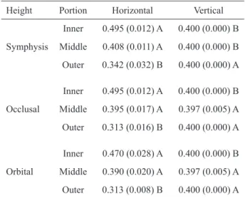
When the measurements of the sphere image size along the horizontal and vertical axes, shown in Table 1, were compared for different portions of the image layer, a statistically significant difference (p<0.05) in magnification between these axes was observed. The variation in sphere image size occurred mainly along the horizontal axis. The magnification along the horizontal and vertical axes was similar (p>0.05) only in middle portion of occlusal and orbital planes.
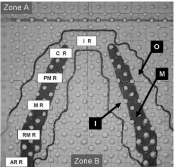
Figure 1 shows the shape of the image layer along the horizontal axis, delimiting the different portions,
Table 1. Measurements of horizontal and vertical axes of the spheres (in cm) in the selection of different portions of the image layer.
Height Portion Horizontal Vertical
Symphysis
Inner 0.495 (0.012) A 0.400 (0.000) B Middle 0.408 (0.011) A 0.400 (0.000) B Outer 0.342 (0.032) B 0.400 (0.000) A
Occlusal
Inner 0.495 (0.012) A 0.400 (0.000) B Middle 0.395 (0.017) A 0.397 (0.005) A Outer 0.313 (0.016) B 0.400 (0.000) A
Orbital
outer, middle and inner, in each anatomical position. The imaged layer has a curved shape, in conformity with the dental arch, presenting the narrowest portion for anterior anatomical positions and being wider for posterior positions. However, the middle portion of the image layer started in the canine region and increased towards the posterior region.
The results of the image size measurements along the horizontal axis in the middle portion of the image layer are shown in Table 2. When the anatomical regions were compared, statistically significant differences in the height of symphysis plane were observed, though without significant differences among the planes (p>0.05). Table 3 presents the results of the image size measurements along the vertical axis in the middle portion of the image layer, which showed no differences (p>0.05) in the comparisons among the anatomical regions and among the planes.
DISCUSSION
It is questionable whether there are precise measurements in panoramic radiographs due to presence of image distortion. However, in some dental specialties, such as orthodontics, dental implantology and oral and maxillofacial surgery, which require a reliable image to
Figure 1. Upper view of the surface of the customized phantom with delimitation of the image layer. “Zone A” represents the out-area of the image layer anterior to it. “Zone B” represents the out-area of the image layer posterior to it. “O”, “M”, “I” represent outer, middle and inner portions of the image layer respectively. The widths of the dental regions are represented as
follows: “I R” the incisor region 1.5 cm; “C R” canine region
1.7 cm; “PM R” premolar region 3.0 cm; “M R” molar region 3.5 cm; “RM R” retromolar region 4.2 cm, and “AR R” angle and ramus region 2.5 cm wide.
Table 2. Mean (sd) of measurements of the spheres along the horizontal axis in the middle portion of the image layer when comparing the different heights and regions.
Regions Symphysis Occlusal Orbital Angle and ramus 0.400
(0.000) Ba
0.385 (0.021) Aa
0.385 (0.021) Aa Canines 0.410
(0.000) Ba
0.400 (0.014) Aa
0.390 (0.028) Aa Incisors 0.430
(0.000) Aa
0.415 (0.021) Aa
0.410 (0.028) Aa Molars 0.400
(0.000) Ba
0.390 (0.014) Aa
0.385 (0.021) Aa Premolars 0.405
(0.007) Ba
0.395 (0.007) Aa
0.385 (0.021) Aa Retromolar 0.400
(0.000) Ba
0.385 (0.021) Aa
0.385 (0.021) Aa Same uppercase letters in columns and lowercase letters in rows indicate no statistically significant difference (Tukey’s test; p>0.05).
Table 3. Mean (sd) of measurements of the spheres along the vertical axis in the middle portion of the image layer when comparing the different heights and regions.
Regions Symphysis Occlusal Orbital Angle and ramus 0.400
(0.000) Aa
0.395 (0.007) Aa
0.395 (0.007) Aa Canines 0.400
(0.000) Aa
0.400 (0.000) Aa
0.400 (0.000) Aa Incisors 0.400
(0.000) Aa
0.400 (0.000) Aa
0.400 (0.000) Aa Molars 0.400
(0.000) Aa
0.395 (0.007) Aa
0.395 (0.007) Aa
Premolars 0.400 (0.000) Aa
0.395 (0.007) Aa
0.395 (0.007) Aa
Retromolar 0.400 (0.000) Aa
0.395 (0.007) Aa
obtain precise measurements for treatment planning, have used this imaging technique in a discriminating manner (9). Thus, linear and angular measurements (10,11) using panoramic images have been recommended for mandibular asymmetry analysis (12,13), measurements of bone width for implant placement (14-16), in addition to performing cephalometric analysis (17). Nevertheless, the main limitation of panoramic radiography is with regard to determining the real dimensions of the radiographic image with precision. In the present study, unrelated magnification along the horizontal and vertical axes was observed, which resulted in overestimation or underestimation of the sphere image size. For determining the length of dental implants (15,18) the panoramic image provides imprecise data, leading to overestimating or underestimating implant measurements.
In addition to unrelated magnification along the horizontal and vertical axes, in the present study a discrepancy was observed between these axes of the spheres located in middle portion of the image layer during image formation along the horizontal axis, which differed according to position of the anatomical region and height of the horizontal plane. Since image formation in panoramic radiography comprises a large number of surrounding anatomical structures in addition to the dental arch, the image layer has three dimensions, i.e., height, width and length. In a previous study, Scarfe et al. (8) evaluating a panoramic machine similar to the model used in the present study, an OP 100 unit, an image layer with similar shape as that of the dental arch was also observed. However, differently from the present study, a large middle portion of the image layer with constant vertical and horizontal magnifications was observed. This difference in results can be explained by the methodology used in present study, which used a high-precision customized phantom, in which the distance between spheres was 0.5 cm, and the images were obtained for each column of each quadrant in an independent manner. Previous studies (2,8,18,20) have reported that the shape and location of the image layer also differed between various panoramic machines. Paiboon and Manson-Hing (20) comparing the image layer of 4 different panoramic machines observed differences among them, which resulted in changes in image formation.
Panoramic image formation depends on the spatial location of anatomical structures in the image layer (7). In the present study, a critical situation was observed as
regards image formation at the mandibular symphysis level, particularly in the anterior region, which showed no middle portion, and significant differences were observed in comparison with other horizontal levels. This fact can be explained by the different distances between the focal point, object and image receptor due to the x-ray beam being fan-shaped. The change in distance among these factors could be corrected if the focal point were converted to line focus, similar to the slit size of the machine, however this is impracticable because the larger the size of the focal area the worse the image precision due to penumbra formation. Thus, the increase in the distance among these factors due to the x-ray beam geometry (3) implies a change in the speed of projection of the anatomical structure in the image receptor during rotation of both the image receptor and the x-ray beam, which causes a discrepancy in image formation between the vertical and horizontal magnifications of the object (4). Therefore, the cause of image distortion is the change in rotation speed of the x-ray beam, which alters the position of effective focus in the image layer along the horizontal axis, in both the length and height of the image layer. Scarfe et al. (8) found an image layer with lower magnification for the maxilla and higher magnification for the mandible. Brown et al. (2), on the other hand, found no change in magnification when evaluating the image layer vertically. Whereas for width, or depth, the rotation speed is constant, which caused a stable magnification in the image layer along the vertical axis (7,19). Previous studies have also found a large difference between the horizontal and vertical magnification (14,17,19). Shiojima et al. (19)reported that in panoramic radiography, vertical measurements are more reliable in comparison with the horizontal measures due to the discrepancy in image magnification between the horizontal and vertical axes.
image layer (4,5). Thus, it is not possible to determine a specific magnifying factor for panoramic machines, as there are wide variations in magnification among the different anatomical regions, axes and planes, making it impossible to obtain reliable anatomical measurements, for any purpose, using panoramic radiographs. Thus the indication of panoramic radiography is clear and should not be overestimated.
In conclusion, according to the methodology used in this study, it was possible determine the precise size, shape and position of the image layer, and differences in magnification along both the horizontal and vertical axes were observed.
RESUMO
O objetivo na presente pesquisa foi determinar o tamanho, forma e
posição da camada de imagem por meio da avaliação da formação
da imagem radiográfica em diferentes posições anatômicas. Foi construído um phantom constituído por uma placa acrílica de 14 cm² e 0,3 cm de espessura, com sua superfície contendo perfurações a cada 0,5 cm dispostas em linhas e colunas. O
phantom foi posicionado no local do apoio de mento do aparelho panorâmico, com sua superfície paralela ao plano horizontal. Esferas metálicas de 0,315 cm foram inseridas nas perfurações, e executadas radiografias panorâmicas. Cada coluna de cada quadrante foi individualmente preenchida pelas esferas para a
execução das radiografias, em três planos horizontais diferentes:
alturas orbital, oclusal e mentual. As imagens das esferas foram medidas com o uso de um paquímetro digital e a camada de imagem localizada. Os dados foram analisados estatisticamente
utilizando-se o teste T Student, ANOVA e teste de Tukey (α=0,05).
Quando o tamanho das esferas nos eixos horizontal e vertical foi
comparado, diferenças estatisticamente significativas (p<0,05)
foram observadas em todas as áreas da camada de imagem,
porções e alturas do plano horizontal avaliado. Na porção central
da camada de imagem diferenças no tamanho das esferas foram
observadas somente no eixo horizontal (p<0,05), enquanto que
no eixo vertical nenhuma diferença foi observada (p>0,05). A
metodologia utilizada determinou com precisão o tamanho, forma e posição da camada de imagem, e diferenças de ampliação foram
observadas tanto no eixo horizontal quanto vertical.
REFERENCES
1. Ogawa K, Langlais RP, McDavid WD, Noujeim M, Seki K, Okano
T, et al.. Development of a new dental panoramic radiographic system based on a tomosynthesis method. Dentomaxillofac Radiol
2010;39:47-53.
2. Brown CE Jr, Christen AC, Jerman AC. Dimensions of the focal trough in panoramic radiography. J Am Dent Assoc
1972;84:843-847.
3. Kaeppler G, Buchgeister M, Reinert S. Influence of the rotation
centre in panoramic radiography. Radiat Prot Dosimetry
2008;128:239-244.
4. Glass BJ, McDavid WD, Welander U, Morris CR. The central
plane of the image layer determined experimentally in various rotational panoramic x-ray machines. Oral Surg Oral Med Oral
Pathol 1985;60:104-112.
5. Fowler P. Limitations of the panoramic radiograph’s focal trough: a case report. New Zealand Dental Journal 1991;87:92-93.
6. Liang H, Frederiksen NL. Focal trough and patient positioning.
Dentomaxillofac Radiol 2004;33:128-129.
7. Laster WS, Ludlow JB, Bailey LJ, Hershey HG. Accuracy
of measurements of mandibular anatomy and prediction of asymmetry in panoramic radiography images. Dentomaxillofac
Radiol 2005;34:343-349.
8. Scarfe WC, Eraso FE, Farman AG. Characteristics of the Orthopantomograph OP100. Dentomaxillofac Radiol
1998;27:51-57.
9. Volchansky A, Cleaton-Jones P, Drummond S, Bonecker M.
Technique for linear measurement on panoramic and periapical
radiographs: a pilot study. Quintessence Int 2006;37:191-197. 10. Niedzielska IA, Drugacz J, Kus N, Kreska J. Panoramic
radiographic predictors of mandibular third molar eruption. Oral
Surg Oral Med Oral Pathol Oral Radiol Endod 2006;102:154-158.
11. Uthman AT.Retromolar space analysis in relation to selected linear and angular measurements for an Iraqi sample. Oral Surg Oral Med
Oral Pathol Oral Radiol Endod 2007;104:76-82.
12. Van Elslande DC, Russett SJ, Major PW, Flores-Mir C. Mandibular asymmetry diagnosis with panoramic imaging.. Am J Orthod Dentofacial Orthop 2008;134:183-192.
13. Ongkosuwito EM, Dieleman MM, Kuijpers-Jagtman AM, Mulder PG, van Neck JW. Linear mandibular measurements: comparison
between orthopantomograms and lateral cephalograms. Cleft
Palate Craniofac J 2009;46:147-153.
14. Güler AU, Sumer M, Sumer P, Biçer I. The evaluation of vertical heights of maxillary and mandibular bones and the location of anatomic landmarks in panoramic radiographs of edentulous
patients for implant dentistry. J Oral Rehabil 2005;32:741-746. 15. de Morais JA, Sakakura CE, Loffredo Lde C, Scaf G. A survey
of radiographic measurement estimation in assessment of dental
implant length. J Oral Implantol 2007;33:186-190.
16. Nohadani N, Ruf S. Assessment of vertical facial and dentoalveolar
changes using panoramic radiography. Eur J Orthod
2008;30:262-268.
17. Ongkosuwito EM, Dieleman MM, Kuijpers-Jagtman AM, Mulder PG, van Neck JW. Linear mandibular measurements: comparison
between orthopantomograms and lateral cephalograms. Cleft
Palate Craniofac J 2009;46:147-153.
18. Peker I, Alkurt MT, Michcioglu T. The use of 3 different imaging methods for the localization of the mandibular canal in dental
implant planning. Int J Oral Maxillofac Implants
2008;23:463-470.
19. Shiojima M, Bäckström A, Welander U, McDavid WD, Tronje G,
Naitoh M. Layer thickness in panoramic radiography as defined by different noise-equivalent passbands. Oral Surg Oral Med Oral
Pathol 1993;76:244-250.
20. Paiboon C, Manson-Hing LR. Effect of border sharpness on the size and position of the focal trough of panoramic x-ray machines.
Oral Surg Oral Med Oral Pathol 1985;60:670-676.