Average interradicular sites for miniscrew insertion:
should dental crowding be considered?
Michele Tepedino¹, Paolo M. Cattaneo², Francesco Masedu1, Claudio Chimenti1
Objective: To define a map of interradicular spaces where miniscrew can be likely placed at a level covered by attached gingiva, and to assess if a correlation between crowding and availability of space exists. Methods: Panoramic radio-graphs and digital models of 40 patients were selected according to the inclusion criteria. Interradicular spaces were measured on panoramic radiographs, while tooth size-arch length discrepancy was assessed on digital models. Statistical analysis was performed to evaluate if interradicular spaces are influenced by the presence of crowding.
Results: In the mandible, the most convenient sites for miniscrew insertion were in the spaces comprised between second mo-lars and first premomo-lars; in the maxilla, between first momo-lars and second premomo-lars as well as between canines and lateral incisors and between the two central incisors. The interradicular spaces between the maxillary canines and lateral incisors, and between mandibular first and second premolars revealed to be influenced by the presence of dental crowding. Conclusions: The aver-age interradicular sites map hereby proposed can be used as a general guide for miniscrew insertion at the very beginning of orthodontic treatment planning. Then, the clinician should consider the amount of crowding: if this is large, the actual interradicular space in some areas might be significantly different from what reported on average. Individualized radio-graphs for every patient are still recommended.
Keywords: Orthodontic mini-implant. Digital models. Anatomy. Safe zones.
1 University of L’Aquila, Department of Biotechnological and Applied Clinical
Sciences (L’Aquila, Italy).
2 Aarhus University, Faculty of Health, Department of Dentistry, Section of
Orthodontics (Aarhus, Denmark).
Submitted: November 17, 2016 - Revised and accepted: March 09, 2017
Contact address: Michele Tepedino – E-mail [email protected]
DOI: https://doi.org/10.1590/2177-6709.22.5.090-097.oar
How to cite: Tepedino M, Cattaneo PM, Masedu F, Chimenti C. Average inter-radicular sites for miniscrew insertion: should dental crowding be considered? Dental Press J Orthod. 2017 Sept-Oct;22(5):90-7.
DOI: https://doi.org/10.1590/2177-6709.22.5.090-097.oar
» The authors report no commercial, proprietary or financial interest in the products or companies described in this article.
Objetivo: elaborar um mapa dos espaços inter-radiculares nos quais os mini-implantes podem ser inseridos, em um nível coberto por gengiva inserida; e avaliar se existe correlação entre o apinhamento dentário e a disponibilidade de espaços. Méto-dos: radiografias panorâmicas e modelos digitais de 40 pacientes foram selecionados seguindo critérios de inclusão. Os espaços inter-radiculares foram medidos nas radiografias panorâmicas, enquanto a discrepância de modelo foi avaliada nos modelos digitais. Realizou-se, então, uma análise estatística para avaliar se os espaços inter-radiculares foram influenciados pela presença do apinhamento dentário. Resultados: na mandíbula, os locais mais adequados para a inserção dos mini-implantes foram os espaços compreendidos entre os segundos molares e primeiros pré-molares; na maxila, entre os primeiros molares e segundos pré-molares, bem como entre caninos e incisivos laterais, e entre os dois incisivos centrais. Os espaços inter-radiculares entre os caninos e incisivos laterais superiores e entre o primeiro e o segundo pré-molares inferiores mostraram-se influenciados pela presença do apinhamento dentário. Conclusões: o mapa dos espaços inter-radiculares mais adequados aqui proposto pode ser adotado como um guia geral para a inserção de mini-implantes, e pode ser usado logo ao início do planejamento do tratamento ortodôntico. Em seguida, o clínico deve levar em consideração a quantidade de apinhamento: caso esse seja grande, o real espaço inter-radicular, em algumas áreas, poderá ser significativamente diferente da média aqui relatada. As-sim, recomenda-se que sempre sejam feitas radiografias individualizadas para cada paciente.
INTRODUCTION
Orthodontic miniscrews are devices specifically designed to be temporarily inserted in the maxillo-facial bones to provide anchorage for an orthodontic appliance.1 They are commonly used when patient compliance is an issue, when there are insufficient teeth to assure an appropriate biomechanics, or when anchorage management is critical.2 Their suc-cess rate is reported to be between 61% and 100%, 3-5 and is affected by many factors: miniscrews
di-mensions, geometry, surface characteristics, surgical technique and clinician’s experience, bone quantity and quality, loading force, primary stability and oral hygiene.3,6-9 Also, root proximity appears to also have a role.10 Therefore, the choice of an appropriate insertion site is critical.
Many authors have tried to define a map of “safe zones” for miniscrews insertion: Schnelle et al11 as-sessed on panoramic radiographs the presence of at least 3 or 4 mm of bone between two adjacent roots, in order to define a map of the interradicular sites where most likely a miniscrew can be safely placed. The authors decided to use the reference of 3 and 4 mm of space considering a miniscrew diameter be-tween 1.2 and 2 mm, and the need of at least 1 mm of bone around the miniscrew. Other authors mea-sured the space between roots at different levels on
panoramic radiographs12 or Cone Beam Computed
Tomography (CBCT).13-17 Nevertheless, in order
to have a convenient primary stability of the mini-screw, the quality of the cortical bone seems to be crucial; thus, many authors have investigated the variation of thickness of the buccal cortical plate of maxillary and mandibular bone between different sites.14,15,18,19 One study used micro-CTs on autopsy material to evaluate the cortical thickness in the pos-terior region of maxillary and mandibular bones and the possible interference with the maxillary sinus.20 From a systematic literature review emerges that the ideal sites for the placement of orthodontic mini-screw in both the maxilla and the mandible, tak-ing into consideration quantity and quality of bone, are the buccal and lingual interradicular spaces be-tween the second premolar and the second molar.21 Moreover, another important aspect for the success of miniscrews insertion is their placement in the at-tached gingiva:22,23 indeed, this is not affected by
tis-sue movements, hygiene maneuvers are simpler and the risk of tissue irritation is lower. Some authors11,16 measured the interradicular spaces together with the height of attached gingiva. These investigations re-vealed that, in many cases, the requested amount of interradicular bone is first available far beyond the muco-gingival line.
An interesting information is that the availability of bone between the roots is influenced by the posi-tion of the teeth, for example when a malocclusion or dental crowding is present. A study showed that for different malocclusions there are differences in bone availability between the roots;24 the authors related this finding to changes in teeth axial inclination de-pending on dentoalveolar compensation, which is a consequence of the presence of a skeletal malocclu-sion. Also, Schnelle et al11 found that in orthodontic patients, after tooth alignment there were more avail-able spaces for miniscrews positioning than before treatment. To the knowledge of the authors, no one tried to find if there is a correlation between quantity of interradicular bone and dental crowding.
The objectives of this study were: 1) to define an average map of the interradicular spaces where is pos-sible to find at least 3 mm of bone available for mini-screw insertion at an height level that is likely to be covered by attached gingiva; 2) to investigate whether it is possible to estimate the interradicular bone avail-ability for miniscrew positioning considering the crowding of the arches, in order to give to the clini-cian a possible non-radiological method to estimate the likelihood of miniscrew insertion. The null hy-pothesis was that no correlation exists between dental crowding and amount of interradicular space.
MATERIAL AND METHODS
No previous work assessed interaction between dental crowding and interradicular spaces; therefore, it was not possible to retrieve suggestions from the literature about a plausible correlation coefficient r estimate. According to Cohen’s criteria,25 an expect-ed r= 0.50 corresponding to a large effect size was as-sumed: having a power of 90% and a Type I error of 5%, a sample size estimate of n = 38 was calculated.
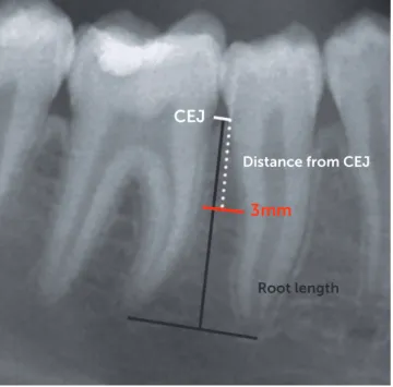
Figure 1 - Schematic representation of the method used to measure interra-dicular spaces. First, the cemento-enamel junction (CEJ) of the two adjacent teeth was identified. Starting from the CEJ, a ruler was scrolled down toward the root apex until 3 mm of horizontal interradicular space was found; then, the distance from the CEJ was measured as well as the total root length from the CEJ to the apex.
2013 were screened. Sixty-two patients were select-ed according to the following inclusion criteria:
» Age between 14 and 35 years.
» Full permanent dentition, with all the second molars fully erupted.
» No agenesis or missing teeth.
» Absence of signs of periodontal disease assessed on panoramic radiographs.
For each patient, pre-treatment digital panoramic radiograph and dental casts were collected. The op-erator who made the measurements was blinded so that it was not possible to associate one panoramic ra-diograph with the respective plaster model. This was done by assigning a random number to each pan-oramic radiograph and dental cast, using an online tool (www.randomizer.org).
Panoramic radiographs
All the radiographs were taken by the same, well-trained dental radiologist, with the same machine (Or-thopantomograph® OP200, Instrumentarium Dental, Tuusula, Finland) on a consecutive period of time. All the measurements were carried out by the same op-erator using Adobe Photoshop CS3 sotware (Adobe Systems Incorporated, San Jose, California, USA).
Starting from the interradicular space mesial to the second molar, a virtual ruler was moved down perpen-dicular to the roots starting from the cemento-enamel junction (CEJ) toward the root apex, until 3 mm of space between the roots of the two adjacent teeth were found (Fig 1). The vertical distance from the CEJ to this point was recorded: to avoid the measurement er-ror caused by the vertical magniication present in the radiographs, this distance was used to calculate a ratio based on the shorter length of the two roots adjacent to the actual interradicular space. In this way, the distance could be expressed as a percentage of the roots length, instead of a distance in millimeters. A reported value of 100% therefore means that a space of at least 3 mm was not available between the two considered adjacent roots at any distance from the CEJ. The horizontal measure-ments of 3 mm of interradicular space were adjusted ac-cordingly to the average magniication factor reported by the manufacturer of the radiographic machine.
These measurements were then used to deine a map of interradicular spaces for miniscrew insertion. The interradicular spaces where 3 mm of horizontal
space were found at 50% or less of the root length were considered ideal insertion sites. If the 3 mm were pres-ent further toward the apex, the interradicular spaces were considered borderline (from 51% to 75% of the root length) or unfavorable sites (beyond 76%).
Digital dental models
To measure the crowding of the arches, the den-tal casts were digitized using an optic scanner (D250, 3Shape, Copenhagen, Denmark) and saved in the STL (stereolithographic) format using a dedicat-ed software (ScanIt Orthodontics 2013, v. 5.5.1.3, 3Shape, Copenhagen, Denmark). The models were thus imported into a model analyzer software (Or-thoAnalyzer 2013, v. 1.5.1.3, 3Shape, Copenhagen, Denmark) where arch crowding was assessed.
CEJ
Root length
3 mm
The crowding of the arches was measured by de-termining the arch-tooth size discrepancy: the width of the teeth, from second premolar to second pre-molar, was measured, then the length of the alveolar base, from the mesial contact point of the first mo-lars, was determined by mean of a curved line passing through the contact point of each teeth.26
Crowding values, expressed in millimeters, were ob-tained from the whole maxillary and mandibular arches, for the anterior segments (between right and let canine) and for the two posterior segments (mesial to the irst molar and distal to the canine) in both arches.
Error of the method
To measure the error of the method, the same op-erator repeated all the measurements concerning in-terradicular spaces and crowding after one week, over 20 randomly selected panoramic radiographs and 20 digital models, and the results were compared using the Dahlberg’s formula to assess the presence of ran-dom errors, and paired samples t-test, to account for any systematic error (p < 0.05).
Statistical analysis
To assess data distribution, the one-sample Kol-mogorov-Smirnov test was performed for all the vari-ables. The independent sample t-test or the Mann-Whitney U test, depending if data were normally dis-tributed or not, was performed to compare all the data of the let and the right sides; if no statistically signiicant diference was found, the data from let and right side were pooled. To evaluate a possible correlation between crowding and availability of interradicular bone, a Pear-son correlation or a Kendall’s tau β test, depending on data distribution, was performed. For all the tests, the significance level was set at 0.05.
RESULTS
Of the 62 selected patients, 22 were excluded be-cause of non-adequate quality of radiographs and/or plaster models; therefore, only 40 patients were in-cluded in the study sample.
The Dahlberg formula revealed a good reliabil-ity for the measurements of interradicular spaces (1.9 ± 1.6%, range 0.1 – 5.4%) and for the assess-ment of crowding on digital models (0.23 ± 0.04 mm, range 0.18 – 0.27 mm). Paired samples t-test revealed
no systematic errors, since all the comparisons were not statistically significant.
In the maxilla, all data concerning interradicular space were not normally distributed, except for the measurements of the interradicular space between ca-nine and lateral incisor of both sides, as well as between the maxillary central incisors, which were normally dis-tributed. In the mandible, all the data were normally distributed except for those concerning the spaces be-tween all the four mandibular incisors. Since all the data regarding crowding were not normally distributed, non-parametric tests were used. The Mann-Whitney U test between data from let and right side revealed no statistically signiicant diference, therefore data for all interradicular spaces as well as for crowding of the pos-terior segments were pooled.
In the maxilla, for all the interradicular spaces, 3 mm of available bone on average were present far beyond halfway the length of the roots (Table 1). The lowest values were found between first molar and second premolar, between canine and lateral incisor and between the two central incisors. In the mandible 3 mm of interradicular space were found at the coro-nal half of the root length between first and second molars, between first molar and second premolar, and between first and second premolars; the worst values were found between the four mandibular incisors. The measurements of interradicular spaces were used to depict the average interradicular sites map (Fig 2).
Concerning crowding, the most crowded seg-ments were the mandibular anterior segment, fol-lowed by the maxillary anterior segment (Table 2).
The Kendall’s tau β test for maxilla revealed a sta-tistically significant correlation (p < 0.05) between crowding and the availability of space between the canine and the lateral incisor (Table 3). In the mandi-ble, Kendall’s tau β test revealed a statistically signifi-cant (p < 0.01) negative correlation between crowding and the availability of space between first and second premolars (Table 3).
DISCUSSION
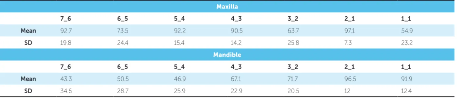
Table 1 - Distance of the available 3 mm of interradicular space from the CEJ (%).
7_6 = interradicular space between second and first molars; 6_5 = interradicular space between first molar and second premolar; 5_4 = interradicular space be-tween second and first premolars; 4_3 = interradicular space between first premolar and canine; 3_2 = interradicular space between canine and lateral incisor;
2_1 = interradicular space between lateral and central incisors; 1_1 = interradicular space between central incisors. Maxilla
7_6 6_5 5_4 4_3 3_2 2_1 1_1
Mean 92.7 73.5 92.2 90.5 63.7 97.1 54.9
SD 19.8 24.4 15.4 14.2 25.8 7.3 23.2
Mandible
7_6 6_5 5_4 4_3 3_2 2_1 1_1
Mean 43.3 50.5 46.9 67.1 71.7 96.5 91.9
SD 34.6 28.7 25.9 22.9 20.5 12 12.4
Table 2 - Crowding measured on digital models (mm).
Maxilla
Right posterior Anterior Left posterior Total
Mean -0.21 -1.84 -0.11 -1.95
SD 0.85 2.54 0.48 3.12
Mandible
Right posterior Anterior Left posterior Total
Mean -0.34 -2.09 -0.34 -2.65
SD 0.78 2.52 1.01 2.9
Table 3 - Correlation between crowding and amount of interradicular space.
*p < 0.05; **p < 0.01; 7_6 = interradicular space between second and first molars; 6_5 = interradicular space between first molar and second premolar; 5_4 = inter-radicular space between second and first premolars; 4_3 = interradicular space between first premolar and canine; 3_2 = interradicular space between canine and lateral incisor; 2_1 = interradicular space between lateral and central incisors; 1_1 = interradicular space between central incisors.
7_6 6_5 5_4 4_3 3_2 2_1 1_1
Maxilla 0.02 0.07 0.061 0.083 0.170* -0.026 0.213
Mandible -0.112 -0.045 -0.224** -0.079 -0.004 0.004 0.005
Figure 2 - Map of interradicular spaces measured on panoramic radiographs. Values are expressed as a ratio between the total root length and the distance of the 3 mm of space from the CEJ.
≤ 50% (ideal insertion sites)
of tomography imaging where a narrow X-ray beam and a detector rotate simultaneously around the pa-tient’s head with multiple centers of rotation, trying to depict a horseshoe-shaped focal trough, as simi-lar as possible to the shape of the mandible. Objects situated outside the focal trough are reproduced with characteristics distortions, and the degrees of mag-nifications vary in the horizontal and vertical planes, therefore, is difficult to obtain precise measures. Nev-ertheless, as for other studies,11,12 it was decided to use panoramic radiographs for the present investigation due to their low radiation dose and because it is closer to what is routinely done in a dental practice, as the use of other sophisticated exams like CBCT is not routinely recommended for miniscrew placement.28
The use of digital models instead of dental casts offers several advantages: analyzing data is easier and faster, there is no need to handle dozens of plaster models and no risk to damage them, data can be di-rectly exported to a database for management, re-ducing possible errors due to manual transcription; furthermore, casts analysis and measurements made on digital models proved to be as accurate and re-producible as those made on plaster models,26,29 and some other authors found that digital models offer even greater reproducibility.30
The first aim of the present study was to define a map of average interradicular sites to provide the clinician information useful during the very begin-ning of orthodontic treatment planbegin-ning.
In this study, the value of 3 mm of bone between two adjacent roots was used as a minimum value of available bone for the placing of a miniscrew of 1.5 mm diameter, taking into account 0.5 mm of bone surrounding the miniscrew and 0.25 mm per side of periodontal width.11,16 In light of this con-sideration, in the present sample a miniscrew could have been placed far halfway the length of the roots in most interradicular spaces. Considering that usu-ally the mucogingival line is coronal to the 50% of the root length, this means that in most of the cases is really difficult to place a miniscrew into attached gingiva, at least referring to mean values of gingiva height found in the literature.31 This is of great im-portance, as having the miniscrew head surrounded by attached gingiva is considered one of the main factors for clinical success.23 Values smaller than
50% were found in the mandible between second molars and first molars, between first molars and second premolars, and between second and first pre-molars. In the maxilla, the most favorable sites were between first molar and second premolar, between canine and lateral incisor and between the two cen-tral incisors. These results are consistent with the findings of Schnelle et al:11 in a study on digital pan-oramic radiographs, they assessed that at most sites adequate bone for placement was located more than halfway down the root length, and that the only place where was possible to place a miniscrew into attached gingiva was between mandibular second and first molars. Moreover, they found that the in-terradicular sites with the best amount of bone were between first molar and second premolar, canine and lateral incisor and between the central incisors in the maxilla; in the mandible, the best locations were be-tween second and first molar, first molar and second premolar, canine and lateral incisor. Their results are in accordance with those of the present study.
Furthermore, the authors recorded the same measurements on the post orthodontic treatment panoramic radiographs of the same patients: this way they assessed that, having roots parallel and aligned following orthodontic treatment assures in general a greater number of available interradicular spaces.11
The second aim of the present study was to eval-uate if a correlation between crowding and availabil-ity of interradicular space exists, that could be used as a non-radiological method to estimate the feasi-bility of miniscrew insertion. Despite the presence of some severely (more than 10 mm) crowded pa-tients, this sample on average exhibited a mild (less than 4 mm) crowding of the arches. With respect to crowding, statistical analysis in the present study revealed that a correlation existed between maxil-lary canine and lateral incisor, mandibular first and second premolar and the crowding of the respective arch segments, therefore the null hypothesis should be partly rejected. The data for maxillary canine and lateral incisors are in accordance with those of Schnelle et al:11 less crowding means more space for miniscrew positioning.
the roots. This finding can be confusing. Probably, that’s because in most of the cases mandibular pre-molars were rotated. A rotated tooth occupy a space in the arch greater than its mesio-distal width: there-fore, when measuring tooth-arch size discrepancy, an excess of space will come out; on the other hand, when measuring interradicular space on panoramic radiograph, a rotated root has an apparent greater width (since panoramic imaging is a two-dimension-al projection and roots are wider in the linguo-bucctwo-dimension-al direction) and there seems to be less available bone.
In light of the outcomes of the present study, when planning miniscrew insertion at the very beginning of orthodontic treatment outlining, the clinician should be aware of the average interradicular sites map here-in provided, which suggests where most likely mhere-inis- minis-crews could be placed, and that in presence of crowd-ing the actual interradicular space available for some areas might be significantly different from average values reported in the literature. An individualized investigation for every single patient, with a radio-graphic technique different from panoramic images, is still recommended prior to miniscrew insertion.
CONCLUSIONS
Within the limitations of the present study, man-dibular interradicular sites where an amount of 3 mm of bone and in a place covered by attached gingiva are to be most likely found between second and first molars, between first molar and second premolar, and between second and first premolars; in the maxilla, they could be found between first molar and second premolar, between canine and lateral incisor and be-tween the two central incisors.
In addition, some interradicular spaces were found to be influenced by the presence of crowd-ing in the arches. Therefore, in the initial phases of the orthodontic treatment and when miniscrews are needed, the clinician should be aware of these cor-relations that can alter what is commonly reported in the literature.
Acknowledgements
1. Elias CN, Ruellas ACO, Fernandes DJ. Orthodontic Implants: concepts for the orthodontic practitioner. Int J Dent. 2012(2012):Article ID 549761, 7 pages
2. Papadopoulos MA, Tarawneh F. The use of miniscrew implants for
temporary skeletal anchorage in orthodontics: a comprehensive review. Oral Surg Oral Med Oral Pathol Oral Radiol Endod. 2007 May;103(5):e6-15. 3. Cornelis MA, Scheler NR, De Clerck HJ, Tulloch JF, Behets CN.
Systematic review of the experimental use of temporary skeletal anchorage devices in orthodontics. Am J Orthod Dentofacial Orthop. 2007 Apr; 131(4 Suppl):S52-8.
4. Tsui WK, Chua HD, Cheung LK. Bone anchor systems for orthodontic
application: a systematic review. Int J Oral Maxillofac Surg. 2012 Nov;41(11):1427-38.
5. Park HS, Jeong SH, Kwon OW. Factors afecting the clinical success of screw implants used as orthodontic anchorage. Am J Orthod Dentofacial Orthop. 2006 July;130(1):18-25.
6. Cheng SJ, Tseng IY, Lee JJ, Kok SH. A prospective study of the risk factors associated with failure of mini-implants used for orthodontic anchorage. Int J Oral Maxillofac Implants. 2004 Jan-Feb;19(1):100-6.
7. Melsen B, Costa A. Immediate loading of implants used for orthodontic anchorage. Clin Orthod Res. 2000 Feb;3(1):23-8.
8. Miyawaki S, Koyama I, Inoue M, Mishima K, Sugahara T, Takano-Yamamoto T.
Factors associated with the stability of titanium screws placed in the posterior region for orthodontic anchorage. Am J Orthod Dentofacial Orthop. 2003 Oct;124(4):373-8.
9. Wehrbein H, Göllner P. Miniscrews or palatal implants for skeletal anchorage in the maxilla : comparative aspects for decision making. World J Orthod. 2008 Spring;9(1):63-73.
10. Kuroda S, Yamada K, Deguchi T, Hashimoto T, Kyung HM, Takano-Yamamoto T. Root proximity is a major factor for screw failure in orthodontic anchorage. Am J Orthod Dentofacial Orthop. 2007 Apr; 131(4 Suppl):S68-73.
11. Schnelle MA, Beck FM, Jaynes RM, Huja SS. A radiographic evaluation of the availability of bone for placement of miniscrews. Angle Orthod. 2004 Dec;74(6):832-7.
12. Wey MC, Shim CN, Lee MY, Jamaluddin M, Ngeow WC. The safety zone for mini-implant maxillary anchorage in Mongoloids. Aust Orthod J. 2012 May;28(1):17-21.
13. Choi JH, Yu HS, Lee KJ, Park Y-C. Three-dimensional evaluation of maxillary anterior alveolar bone for optimal placement of miniscrew implants. Korean J Orthod. 2014 Mar;44(2):54-61.
14. Deguchi T, Nasu M, Murakami K, Yabuuchi T, Kamioka H, Takano-Yamamoto T. Quantitative evaluation of cortical bone thickness with computed tomographic scanning for orthodontic implants. Am J Orthod Dentofacial Orthop. 2006 June;129(6):721.e7-12.
15. Fayed mm, Pazera P, Katsaros C. Optimal sites for orthodontic mini-implant placement assessed by cone beam computed tomography. Angle Orthod. 2010 Sept;80(5):939-51.
REFERENCES
16. Ludwig B, Glasl B, Kinzinger GS, Lietz T, Lisson JA. Anatomical guidelines for miniscrew insertion: Vestibular interradicular sites. J Clin Orthod. 2011 Mar;45(3):165-73.
17. Poggio PM, Incorvati C, Velo S, Carano A. “Safe zones”: a guide for miniscrew positioning in the maxillary and mandibular arch. Angle Orthod. 2006 Mar;76(2):191-7.
18. Baumgaertel S, Hans MG. Buccal cortical bone thickness for mini-implant placement. Am J Orthod Dentofacial Orthop. 2009 Aug;136(2):230-5. 19. Farnsworth D, Rossouw PE, Ceen RF, Buschang PH. Cortical bone thickness
at common miniscrew implant placement sites Am J Orthod Dentofacial Orthop. 2011 Apr;139(4):495-503.
20. Laursen MG, Melsen B, Cattaneo PM. An evaluation of insertion sites for mini-implants A micro-CT study of human autopsy material. Angle Orthod. 2013 Mar;83(2):222-9.
21. AlSamak S, Gkantidis N, Bitsanis E, Christou P. Assessment of potential orthodontic mini-implant insertion sites based on anatomical hard tissue parameters: a systematic review. Int J Oral Maxillofac Implants. 2012 July-Aug;27(4):875-87.
22. Viwattanatipa N, Thanakitcharu S, Uttraravichien A, Pitiphat W. Survival analyses of surgical miniscrews as orthodontic anchorage. Am J Orthod Dentofacial Orthop. 2009 July;136(1):29-36.
23. Baumgaertel S. Hard and soft tissue considerations at mini-implant insertion sites. J Orthod. 2014 Sept;41 Suppl 1:S3-7.
24. Chaimanee P, Suzuki B, Suzuki EY. “Safe zones” for miniscrew implant placement in diferent dentoskeletal patterns. Angle Orthod. 2011 May;81(3):397-403.
25. Cohen J. A Power Primer. Psychol Bull. 1992;112(1):155–9.
26. Correia GD, Habib FA, Vogel CJ. Tooth-size discrepancy: a comparison between manual and digital methods. Dental Press J Orthod. 2014 July-Aug;19(4):107-13.
27. Van Elslande DC, Russett SJ, Major PW, Flores-Mir C. Mandibular asymmetry diagnosis with panoramic imaging. Am J Orthod Dentofacial Orthop. 2008 Aug;134(2):183-92.
28. Kapila SD, Nervina JM. CBCT in Orthodontics: assessment of treatment outcomes and indications for its use. Dentomaxillofac Radiol. 2015;44(1):20140282.
29. Bootvong K, Liu Z, McGrath C, Hägg U, Wong RW, Bendeus M, et al. Virtual model analysis as an alternative approach to plaster model analysis: reliability and validity. Eur J Orthod. 2010 Oct;32(5):589-95.
30. Dowling AH, Burns A, Macauley D, Garvey TM, Fleming GJ. Can the intra-examiner variability of Little’s Irregularity Index be improved using 3D digital models of study casts? J Dent. 2013 Dec;41(12):1271-80.