Quantification of intrusive/retraction force and moment
generated during en-masse retraction of maxillary anterior
teeth using mini-implants: A conceptual approach
A. Sumathi Felicita1
Objective: The aim of the present study was to clarify the biomechanics of en-masse retraction of the upper anterior teeth and
at-tempt to quantify the different forces and moments generated using mini-implants and to calculate the amount of applied force optimal for en-masse intrusion and retraction using mini-implants. Methods: The optimum force required for en-masse intrusion and retraction can be calculated by using simple mathematical formulae. Depending on the position of the mini-implant and the relationship of the attachment to the center of resistance of the anterior segment, different clinical outcomes are encountered. Using certain mathematical formulae, accurate measurements of the magnitude of force and moment generated on the teeth can be calculated for each clinical outcome. Results: Optimum force for en-masse intrusion and retraction of maxillary anterior teeth is
212 grams per side. Force applied at an angle of 5o to 16o from the occlusal plane produce intrusive and retraction force components that
are within the physiologic limit. Conclusion: Different clinical outcomes are encountered depending on the position of the mini-im-plant and the length of the attachment. It is possible to calculate the forces and moments generated for any given magnitude of applied force. The orthodontist can apply the basic biomechanical principles mentioned in this study to calculate the forces and moments for different hypothetical clinical scenarios.Keywords:Orthodontics. Orthodontic space closure. Orthodontic anchorage procedures.
1 Saveetha University, Saveetha Dental College, Department of Orthodontics
and Dentofacial Orthopedics (Chennai, India).
Contact address: A. Sumathi Felicita E-mail: [email protected]
DOI: https://doi.org/10.1590/2177-6709.22.5.047-055.oar
How to cite: Felicita AS. Quantification of intrusive/retraction force and moment generated during en-masse retraction of maxillary anterior teeth using mini-im-plants: a conceptual approach. Dental Press J Orthod. 2017 Sept-Oct;22(5):47-55. DOI: https://doi.org/10.1590/2177-6709.22.5.047-055.oar
Submitted: August 18, 2016 - Revised and accepted: January 13, 2017
» The authors report no commercial, proprietary or financial interest in the products or companies described in this article.
» Patients displayed in this article previously approved the use of their facial and in-traoral photographs.
Objetivo: o objetivo do presente estudo foi explicar o funcionamento da biomecânica de retração em massa dos dentes
anterossupe-riores e tentar quantificar as diferentes forças e momentos gerados ao se usar mini-implantes, além de calcular a quantidade ideal de força a ser aplicada para se obter a intrusão/retração em massa ancorada em mini-implantes. Métodos: a força ideal necessária para se realizar a intrusão/retração em massa pode ser calculada por meio de fórmulas matemáticas simples. Dependendo da posição do mini--implante e da posição do acessório, a ele conectado, com relação ao centro de resistência do segmento anterior, obtêm-se desfechos clínicos diferentes. Aplicando certas fórmulas matemáticas, pode-se calcular com precisão a magnitude da força e do momento gerado nos dentes, para cada desfecho clínico. Resultados: a força ideal para se obter a intrusão/retração em massa dos dentes
anterossuperio-res é de 212 gramas por lado. A força aplicada em um ângulo de 5° a 16° em relação ao plano oclusal produz componentes de força de intrusão/retração que se encontram dentro dos limites fisiológicos. Conclusão: podem ser encontrados diferentes desfechos clínicos dependendo da posição do mini-implante e do comprimento do acessório. É possível calcular as forças e os momentos gerados para qualquer magnitude de força aplicada. Assim, o ortodontista clínico pode aplicar os princípios biomecânicos básicos apresentados nesse estudo para calcular as forças e os momentos em diferentes cenários clínicos hipotéticos.
INTRODUCTION
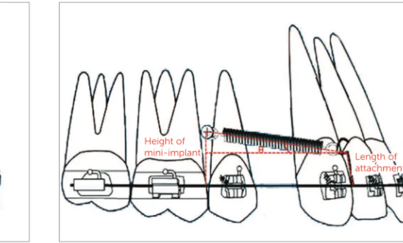
Space closure with mini-implant anchorage usu-ally involves application of force by means of closed coil spring or elastic traction from the mini-implant placed between the maxillary second premolar and maxillary irst molar, bilaterally1-7, to an attachment placed be-tween the lateral incisor and canine, on a continuous archwire (Fig 1). This usually results in the application of a diagonal vector of force on the maxillary anterior teeth of both sides. This applied diagonal force vector can be resolved into an intrusive and retraction com-ponent, and its magnitude depends on the direction of applied force, in relation to the occlusal plane. This di-rection of applied force is determined by the length of the attachment and the height of the mini-implant from the base archwire (Fig 2). Therefore, the direction of ap-plied force becomes more obtuse as the length of the at-tachment is reduced and the height of the mini-implant is increased, and vice versa.
However, retraction on a continuous archwire pro-duces a statically indeterminate system and cannot be quantiied. But if the base archwire is segmented distal to the canine on both sides, it is possible to produce a statically determinate force system that can be accurately calculated. This paper deals with a statically determinate force system. Thus, the aim of this paper is:
1. To calculate the magnitude of optimum force re-quired for en-masse retraction using mini-implants.
2. To determine the optimum direction of applied force to produce optimum resultant forces.
Figure 1 - Force applied from the mini-implant placed between the maxillary second premolar and first molar to an attachment soldered onto the arch-wire distal to the lateral incisor.
Figure 2 - Showing the angulation made by the applied force to the horizon-tal, depending on the height of the soldered attachment and the height of the mini-implant from the base archwire.
3. To quantify the magnitude of force and moment generated for any given clinical outcome.
MATERIAL AND METHODS
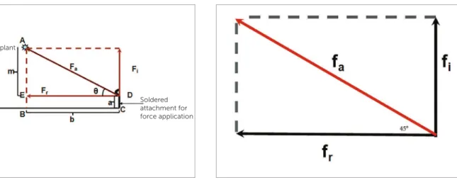
The direction of force application from the maxillary anterior teeth to the mini-implant can be represented using a simple mathematical model (Fig 3). This model is designed based on the parallelogram law of forces. Ac-cording to the parallelogram law of vectors, a parallelo-gram has two adjacent sides, that represent two force vectors; and a diagonal, which is the resultant sum of the two vectors. For all practical purposes, resolution of a diagonal force in orthodontics is done with two vectors perpendicular to each other,9 and the direction of resul-tant force at an angle of 45° to the occlusal plane (Fig 4). According to this model, the magnitude of applied force can be calculated using the formula:9 F
a = √ (fi2 + fr2). The optimum force for simultaneous intrusion and re-traction of anterior teeth = √ (2102 + 302) =√ (44,100 + 900) = 212.132 g, since optimum force required to translate a single anterior tooth is 70g8 and that required to intrude one anterior teeth is 10g8.
However, in a clinical situation the force is not al-ways applied at 45° to the occlusal plane and varies de-pending on the length of attachment and height of the mini-implant from the occlusal plane. Hence for any given clinical situation the direction of applied force to the occlusal plane can make an angle ‘θ’ which can vary from 0° to 90°. This angle can be derived either by the direct method or indirect method.
Height of
Figure 3 - Showing the parallelogram law of vectors with fa being the resul-tant force of the two individual forces fi and fr.
Figure 4 - Showing fa as the hypotenuse of a right angled triangle with the component vectors fi and fr forming the other two sides of the triangle.
Direct method
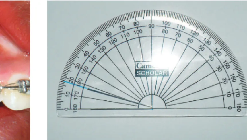
Bend a stif straight length 0.07” round wire. The bent wire is adjusted such that the upper end of the bent wire is placed on the coil spring, the vertex of the bent wire is placed on the point of force application on the attachment and the lower end of the bent wire is placed parallel to the base archwire. This angulation obtained is measured to the nearest degree (Fig 5).
Indirect method
The angulation of the applied force can also be obtained from certain intraoral linear measurements. The following measurements are made, as shown in Figures 6A and 6B: AE, denoted as ‘m’; EB = DC, de-noted as ‘a’; and BC = ED, dede-noted as ‘b’ — where ‘m’ is the perpendicular distance in millimeters from the mini-implant to the base archwire; ‘a’ is the length of the attachment in millimeters from the point of at-tachment on the base archwire to the point of attach-ment of the coil spring; and ‘b’ is the linear horizontal distance between the perpendicular from the mini-implant to the base archwire and the attachment on the base archwire.
Now, according to Figure 6:
» AE= AB minus EB=AB minus DC (since EB=DC); » AED is a right angled triangle with an angle θ be-tween AD and ED. To determine ‘θ’:
» θ = Cos (adjacent side/hypotenuse) = Sin (oppo-site side/ hypotenuse) = tan (oppoSin (oppo-site side/ adjacent side).
Using any of the aforementioned equations the value of ‘θ’ can be determined: ‘θ’ gives the direction of ap-plied force.
However, the intrusive and retraction forces gen-erated for any given direction ‘θ’ of the applied force may not be optimum, as shown in Table 1, and it is im-perative to determine the optimum direction of applied force from the mini-implant to the anterior teeth.
The value of 212 g is the optimum force applied from the attachment on the base archwire to the mini-im-plant. The magnitude of applied force can be accurately measured using a Dontrix gauge (TP Orthodontics, Inc.) or a Corex gauge (Haag- Streit AG, Gartenstad-strasse 10, 3098 Koeniz, Switzerland).
Theoretically, the direction of this force can range from 0° to 90°. Using the same mathematical model as above, the resultant forces for a clinical situation as shown in Figure 3 can be calculated. For a given clinical situa-tion where the optimum diagonal force of 212 g per side is at 16° to the horizontal — as determined using either the direct or the indirect method —, the retraction and intrusive force generated can be calculated as follows:
Fr = F x Cos θ
Retraction force = Fr = 212 x Cos 16 = 212 x 0.2756 = 58.4272 g Therefore, Fi = F x Sin θ
Fi = Intrusive force = 212 x Sin 16 = 212 x 0.9613 = 203.7956 g Mini-implant
Base archwire Soldered attachment for
Figure 5 - Direct measurement of the angle made by the applied force to the occlusal plane.
Figure 6 - Indirect measurement of the angle made by the applied force to the occlusal plane.
Table 1 gives the intrusive and retraction force generated for an optimum force of 212 g for differ-ent angulations. It can be noted that the intrusive component of force is beyond the physiologic limit for an angulation of 17° with an intrusive force of 61.98888 g.
The optimum force and the optimum direction of force application have now been established. But in a clinical situation the applied force does not always pass through the center of resistance of the maxillary ante-rior teeth and moments are generated depending on the relation between the direction of applied force and the center of resistance of the anterior teeth. The magni-tude of these moments is given as:
» Moment of a given force = Distance between the CRes and the point of force application x Force.
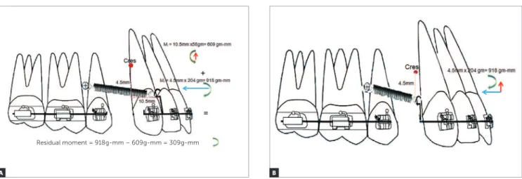
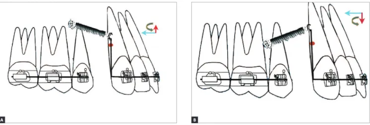
» The moment generated by the horizontal compo-nent of force = Vertical Distance from the CRes to the point of force application x horizontal force (calculated retraction force at an angle of 16°)
= Mr = 4.5 mm x 204 g = 918 g-mm per side (Fig 7A). The moment generated by the vertical component of force = Horizontal Distance from the CRes to the point of force application x vertical force (calculated intrusive force at 16°)
= Mi = 10.5 mm x 58 g = 609 g-mm per side (Fig 7A). The vertical and horizontal distance was determined from the vertical and sagittal position of the CRes. The center of resistance varies from 8.1 mm to 14.7 mm from the incisal edge in the vertical direction when a sagittal force is applied on the six anterior teeth.10 The length of the attachment determines the distance
Soldered attachment for force application Mini-implant
between the CRes and the point of force application. In the described situation the attachment was placed 4.5 mm incisal to the CRes.
In the sagittal direction the center of resistance is lo-cated on a line 3 mm behind the distal surface of the maxillary canine, when a vertical force is applied to the six anterior teeth11. Since the mesiodistal width of the upper permanent canine in Caucasians is 7.5-8 mm12 the center of resistance lies 10.5-11mm distal to the at-tachment, in the sagittal direction.
Since the retraction force is occlusal to the center of resistance, a clockwise moment is generated by the retraction force and the intrusive force is labial to the CRes, an anticlockwise moment is generated.
Therefore:
» residual moment = diference between clockwise and anticlockwise moments =
» 918 g-mm – 609 g-mm = 309 g-mm per side.
Thus, the total residual moment produced is a clockwise moment of 309 g-mm per side at an angle of 16°. Tipping of the maxillary anterior teeth may be expected due to the clockwise moment. The mo-ment generated for varying lengths of attachThe mo-ment can also be calculated.
If the point of force application is placed distal to the canine, 4.5 mm occlusal to the CRes, the intru-sive force passes through the CRes and a clockwise moment of 918 g-mm is created because of the retrac-tion force (Fig 7B).
Figure 7 - A) Calculation of residual moment when the attachment is placed between the lateral incisor and canine. B) Calculation of moment when the attach-ment is placed distal to the canine.
Degrees Intrusive force
(grams)
Retraction force
(grams)
0 0 212
5 18.4864 211.1944
6 22.154 210.834
7 25.8428 210.41
8 29.5104 209.9436
9 33.1568 209.3924
10 36.8032 208.7776
11 40.4496 208.0992
12 44.0748 207.3572
13 47.7 206.5728
14 51.2828 205.7036
15 54.8656 204.7708
16 58.4272 203.7956
17 61.9888 202.7356
18 65.508 201.6332
19 69.0272 200.446
20 72.504 199.2164
30 106 183.592
40 136.2736 162.392
50 162.392 136.2736
60 183.592 106
70 199.2164 72.504
80 208.7776 36.8032
90 212 0
Table 1 - The intrusive and retraction force generated for a diagonal force of 212 grams for different angulations.
A B
RESULTS
The amount of 212 grams is the optimum force re-quired for en-masse intrusion and retraction of anterior teeth using mini-implants.
However, the resultant forces are optimum when the direction of force application ranges from 5° to 16°.
A residual moment of 309 g was produced when an optimum force of 212 g was applied at 16° to the occlu-sal plane when the attachment was placed between the lateral incisor and canine.
A residual clockwise moment of 918 g was produced when an optimum force of 212 g was applied at 16° to the occlusal plane when the attachment was placed dis-tal to the canine.
The residual moment generated is definitely smaller when the attachment is placed between the lateral incisor and canine, as compared to that placed distal to the canine.
DISCUSSION
The diferent clinical outcomes encountered during en-masse retraction using mini-implants can be classi-ied into three types, depending on the relation between the point of force application and the center of resistance of the maxillary anterior teeth.
» Outcome I: The point of force application lies apical to the center of resistance of the maxillary an-terior teeth (There are two sub-types, depending on the relation between the mini-implant and the point of force application).
» Outcome IA: When the point of force application is located apical to the center of resistance of the maxil-lary anterior teeth and occlusal to the mini-implant, a counter-clockwise moment is generated along with an intrusive and retraction component of force (Fig 8A). This counter-clockwise moment will result in labial laring of the teeth, with bite-opening augmenting the efect of the mild intrusive force component. The mag-nitude of retraction force component should be sui-cient to overcome the laring of the anterior teeth prior to retraction.
» Outcome IB: When the point of force application is apical to the center of resistance and the mini-implant, a large counter-clockwise moment is generated, with an extrusive and retraction component of force (Fig 8B). The large counter-clockwise moment can cause severe labial laring with associated bite opening, which may
be partly negated by the mild extrusion caused by the extrusive component of force. Hence only retraction of teeth can be expected. The retraction force has to over-come the labial laring of the teeth to allow them to be retracted.
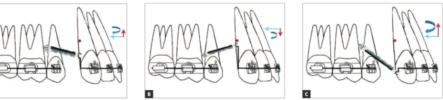
» Outcome II: The point of force application lies on the CRes of the maxillary anterior teeth; if the point of force application lies on the center of resis-tance of the maxillary anterior teeth, bodily move-ment of maxillary anterior teeth occurs (there are the following three situations, depending on the position of the mini-implant and the attachment).
» Outcome IIA: If the mini-implant is apical to the center of resistance, an intrusive and retraction force is generated, without any moment (Fig 9A). True intru-sion and translation can be expected.
» Outcome IIB: If the mini-implant is at the level of center of resistance, only a retraction force is gener-ated, without any moment (Fig 9B). If the implant is in the same plane of the center of resistance and the force passes through the center of resistance, only translation with no intrusion will take place.
» Outcome IIC: If the mini-implant is occlusal to the center of resistance, an extrusive and retraction force is generated, without any moment (Fig 9C). True ex-trusion and translation will occur.
» Outcome III: The point of force application lies occlusal to the CRes of the maxillary anterior teeth (there are the following three types, depending on the relation between the mini-implant and the point of force application).
» Outcome IIIA: If the point of force application is occlusal to the mini-implant and the center of resistance of the maxillary anterior teeth and apical to the base arch-wire, an intrusive and retraction force is generated along with a clockwise moment (Fig 10A). This will result in lingual tipping of the teeth, with bite deepening. Howev-er, this may be negated by the intrusive force component. Therefore, only retraction of the teeth will be attained.
» Outcome IIIC: If the point of force application is at the level of the occlusal plane and occlusal to the center of resistance of the maxillary anterior teeth, a large clockwise moment is generated. A greater intrusive force is generated along with a retraction force (Fig 10C).
Since the point of force application is far away from the CRes of the maxillary anterior teeth, a greater clockwise moment is generated. However, the intru-sive force may not be suicient to completely negate the bite deepening tendency that may occur due to the clockwise moment, and bite deepening may occur. Ap-plication of force closer to the center of resistance of the maxillary anterior teeth will reduce the moment. This is oten beneicial. Hence, Outcome IIIC may not be ap-propriate from a biomechanical stand point.
Thus, it can be inferred that if a greater intrusive force component is desired, the force should be applied away from the occlusal plane, and vice versa. If a greater
retraction force component is required, applied force should be placed closer to the occlusal plane, and vice versa. It can be stated that pure translation and true in-trusion or exin-trusion of the teeth can be attained only for the coniguration in Outcome II. In Outcomes I and III, tipping is expected to occur depending on the mag-nitude of moment generated. The clinician can adjust the force magnitude according to the intended type of orthodontic movement.
A number of studies13-18 have been done on the center of resistance of the maxillary anterior teeth, and a large variability in the position of the center of resistance was recorded over time, even for the same tooth. As a result, close monitoring of the dental movement is required.
This study in its entirety is a theoretical one and is based on well-known mathematical and physical for-mulae. Application of these situations in clinical practice
Figure 8 - A) Outcome IA: The point of force application is located apical to the CRes of the maxillary anterior teeth but occlusal to the mini-implant. B) Out-come IB: The point of force application is located apical to the CRes of the maxillary anterior teeth and also apical to the mini-implant.
Figure 9 - A) Outcome IIA: The point of force application lies on the CRes of the maxillary anterior teeth occlusal to the mini-implant. B) Outcome IIB: The point of force application lies on the CRes of the maxillary anterior teeth at the level of the mini-implant. C) Outcome IIC: The point of force application lies on the CRes of the maxillary anterior teeth apical to the mini-implant.
A
A
B
Figure 10 - A) Outcome IIIA: The point of force application lies occlusal to the mini-implant and the CRes of the maxillary anterior teeth. B) Outcome IIIB: The point of force application lies apical to the mini-implant occlusal to the CRes of the maxillary anterior teeth. C) Outcome IIIC: The point of force application lies occlusal to the mini-implant but away from the CRes of maxillary anterior teeth slightly occlusal to the base archwire.
A B C
depends on a number of factors like variability in the po-sition of center of resistance, bone heights, root lengths, patient biology, root surface area, binding friction, etc. It would be much more relevant to the practicing or-thodontist to apply the basic biomechanical principles mentioned in this study to calculate the forces/moments prior to the commencement of treatment.
The length and position of the attachment is impor-tant in determining the magnitude of moment gener-ated. The length of attachment can be limited by the depth of the vestibule, as a relatively long attachment can cause sot tissue irritation and ulceration. It is better to place the attachment between the lateral incisor and canine as lesser residual forces are produced, in com-parison to that placed distal to the canine.
It is to be noted that all the mechanics discussed above are for statically determinate system. If the same principles are applied during en-masse retraction on a continuous archwire, a change in the inclination of the occlusal plane can occur because of the moments
pro-duced. When retraction using mini-implants in done on a continuous archwire, it may not be possible to ac-curately predict the magnitude of force generated and its efect on the dentition.
CONCLUSION
1. Optimum force for en-masse intrusion and retrac-tion using mini-implants is 212g per side.
2. Forces applied at an angle of 5° to 16° to the occlu-sal plane produces force components within the physi-ologic limit.
3. An attachment placed between the lateral incisor and the canine result in lesser residual moments and is therefore a better biomechanically eicient system.
1. Park HS, Jeong SH, Kwon OW. Factors afecting the clinical success of screw implants used as orthodontic anchorage. Am J Orthod Dentofacial Orthop. 2006 July;130(1):18-25.
2. Kyung HM, Park HS, Bae SM, Sung JH, Kim IB. Development of orthodontic
micro-implants for intraoral anchorage. J Clin Orthod. 2003 June;37(6): 321-8;quiz 314.
3. Moon CH, Lee DG, Lee HS, Im JS, Baek SH. Factors associated with the success rate of orthodontic miniscrews placed in the upper and lower posterior buccal region. Angle Orthod. 2008 Jan;78(1):101-6.
4. Baumgaertel S, Razavi MR, Hans MG. Mini-implant anchorage for
the orthodontic practitioner. Am J Orthod Dentofacial Orthop. 2008 Apr;133(4):621-7.
5. Herman RJ, Currier GF, Miyake A. Mini-implant anchorage for maxillary canine retraction: a pilot study. Am J Orthod Dentofacial Orthop. 2006 Aug;130(2):228-35.
6. Chung KR, Nelson G, Kim SH, Kook YA. Severe bidentoalveolar protrusion treated with orthodontic microimplant-dependent en-masse retraction. Am J Orthod Dentofacial Orthop. 2007 July;132(1):105-15.
7. Garinkle JS, Cunningham LL Jr, Beeman CS, Kluemper GT, Hicks EP,
Kim MO. Evaluation of orthodontic mini-implant anchorage in premolar extraction therapy in adolescents. Am J Orthod Dentofacial Orthop. 2008 May;133(5):642-53.
8. Proit WR, Fields HW. Contemporary orthodontics. 3rd ed. Saint Louis: Mosby; 2000.
9. Gross D, Hauger W, Schröder J, Wall W, Rajapakse N, Schroder JR, et al. Engineering Mechanics 1: Statics. 1st ed. Berlin: Springer-Verlag; 2013. 10. Reimann S, Keilig L, Jäger A, Bourauel C. Biomechanical inite-element
investigation of the position of the centre of resistance of the upper incisors. Eur J Orthod. 2007 June;29(3):219-24. Epub 2007 Feb 22.
REFERENCES
11. Pedersen E, Isidor F, Gjessing P, Andersen K. Location of centres of resistance for maxillary anterior teeth measured on human autopsy material. Eur J Orthod. 1991 Dec;13(6):452-8.
12. Ash N. Wheeler’s Dental anatomy, physiology and occlusion. 8th ed. Saint Louis: Saunders; 2003.
13. Vanden Bulcke MM, Dermaut LR, Sachdeva RC, Burstone CJ. The center of resistance of anterior teeth during intrusion using the laser relection technique and holographic interferometry. Am J Orthod Dentofacial Orthop. 1986 Sept;90(3):211-20.
14. Vanden Bulcke MM, Burstone CJ, Sachdeva RC, Dermaut LR. Location of the centers of resistance for anterior teeth during retraction using the laser relection technique. Am J Orthod Dentofacial Orthop. 1987 May;91(5):375-84.
15. Choy K, Kim KH, Burstone CJ. Initial changes of centres of rotation of the anterior segment in response to horizontal forces. Eur J Orthod. 2006 Oct;28(5):471-4. Epub 2006 Aug 17.
16. Jeong GM, Sung SJ, Lee KJ, Chun YS, Mo SS. Finite element investigation of the center of resistance of the maxillary dentition. Korean J Orthod. 2009;39(2):83-94.
17. Lee HK, Chung KR. The vertical location of the center of resistance for maxillary six anterior teeth during retraction using three dimensional inite element analysis. Korean J Orthod. 2001;31(4):425-38.