Abstract— Despite its robustness the Switched Reluctance Motors
(SRMs) present some inconvenient drawbacks as a major torque ripple, vibration and acoustic noise when compared to other types of motors. These characteristics are usually related to factors such as the salient poles in the stator and in the rotor, the switched feeding and the control strategy imposed by the electronic converter. In this paper a Special Switched Reluctance Motor for fractional horsepower and high speed hand tool was studied in order to minimize its vibration and torque ripple characteristics. This task was accomplished by the development of a simple and flexible motor drive and the combination of two different commutations strategies: the Three Level Control and the Single Pulse with Overlapping Phase Current. The SRM prototype and its drive were constructed and submitted to several tests with the proposed commutation strategies. In the frequency domain the strategies results were considered satisfactory.
Index Terms— Control Strategies, Switched Reluctance Motor, Torque Ripple, Vibration.
I. INTRODUCTION
The Switched Reluctance Motors (SRMs) present a simple manufacturing characteristic associated
to robustness, reliability and speed when compared to other equivalent machines. However these
machines also present some inconvenient features like non negligible vibration, torque ripple and
acoustic noise. These characteristics are related to factors as rotor and stator double salient poles
geometry, switched drive feeding and control strategy established for the power converter.
Regarding the vibration, it can be classified into mechanical and magnetic origins [1]. The
vibrations of magnetic origin are due to the fluctuations of magnetic forces inside the motor [2], [3].
These forces can be divided in two components, radial and tangential magnetic forces. The radial
components are related to the attraction forces between rotor and stator poles. On the other hand the
tangential components are related to the torque produced between rotor and stator salient poles. The
focus of this work is minimizing the torque ripple produced by the tangential components of force and
the vibrations associate with it.
Control Strategies Applied for Reducing the
Vibration and Torque Ripple of a Special
Switched Reluctance Motor
D. A. P. Correa, W. M. da Silva,
Centro Tecnológico da Marinha em São Paulo, Av. Prof. Lineu Prestes, 2468, Cidade Universitária, São Paulo, SP, CTMSP2, CEP 05508-000, [email protected], [email protected]
S. I. Nabeta, I. E. Chabu
There are basically two methods for reducing the torque ripple and the vibrations in the SRM:
improve the motor’s magnetic design and apply sophisticated control strategies in the SRM drive [4],
[5]. The SRM considered in this work presents a special geometry, depicted in Fig.1, which was
obtained through an optimization procedure based on a Multi-Objective method [6] that aimed the
torque ripple, and consequently the vibration, reduction. In order to further reduce the torque ripple,
this work proposes the assemblage of a dedicated hardware and software for implementing the
aforementioned strategies.
For this purpose, the motor drive hardware used an AC three-phase power module [7], which
brought more simplicity and flexibility to the application. The software is based on a LabView [8]
serial data interface for handling the motor drive parameters like turn-on, turn-off and dwell firing
angles, etc so as to find the best operation point at nominal conditions. Besides, a control software
based on a C code was developed using a DSP development kit [9] aiming the control and
commutation algorithms.
Fig. 1. Special Switched Reluctance Motor for fractional horsepower and high speed hand tool
II. SWITCHED RELUCTANCE MOTOR DRIVE – THE HARDWARE STRUCTURE
In order to simplify the development of the application, the motor drive assignment was divided into
three main blocks: motor, converter and controller [10].
A. Motor
The 4:2 poles – 2 phases Switched Reluctance Motor was proposed as a drive for a fractional
horsepower and high speed hand tool [11]. The SRM has particularly designed rotor poles which
ensure an appropriate unidirectional starting torque at any rotor position. The basic characteristic of
the rotor poles is its geometric asymmetry that consists of one region with a small uniform air-gap and
Fig. 2. Details of the rotor geometry
Applying the Finite Element Method (FEM) associated with a numerical approach based on
Simulated Annealing (SA) and Kriging Method [12], the torque ripple was minimized.
Generally, the minimization of the torque ripple implies in the degradation of other important
features, such as the starting and the average torques. To overcome this, the use of a multi-objective
optimization technique resulted in the reduction of the torque ripple and the raise of the starting torque
while keeping the average torque at his former value [6]. The most significant geometric parameters
chosen for the rotor optimization were β0, lg1 and lg2 (Fig. 2) and the rotor with its new dimensions,
hereafter designated as “optimized” is depicted in Fig. 3(b).
(a) Reference rotor (b) Optimized rotor Fig. 3. Rotor Geometry
B. Converter
The Power Electronic Converter is basically composed of a capacitive filter for the DC bus, the gate
drive circuits and an inverter circuit that performs the commutation of the IGBT power switches. The
DC capacitive filter must be composed of a hundred microfarad capacitor because of the high level of
the SRM phase current harmonics. To implement the gate drive circuit it was used the boot strap
technology associated with a pulse transformer.
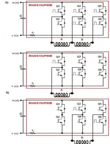
As the control strategies are directly related to the power converter hardware, it was proposed a
Power Electronic Converter that uses AC three-phase power modules (IRAMS10UP60B) [7]
assembled in two configurations. In the first assembly (A) only one power module connected to both
the SRM windings was used, as showed in Fig. 4. In the second assembly (B), two power modules
were used, each one independently connected to one winding. This configuration is known as
following advantages: less connections, reliability and less electromagnetic interference.
Fig. 4. Power Electronic Converter: IRAMS10UP60B, capacitive filter and SRM windings in two configurations A and B
C. Controller
The controller is based on the DSP development kit (eZdsp LF2407A) [9]. The choice of the DSP
controller is justified by the requirements of high frequency bandwidth and accuracy. The DSP
controller tasks include the commutation of the inverter IGBT switches, commands generation, the
processing of control algorithms, the data communication and the supervising of variables. Moreover,
it was necessary to implement a LabView algorithm for loading the input parameters (the angles θon,
θoff and θc for example) and for finding the optimal operation point related to the vibration. Once the
parameters were loaded in the graphic interface, they were sent to the DSP board that executed the
desired commutation profile.
III. THE CONTROL AND COMMUTATION STRATEGIES
SRMs operating in high speed have a limited processing time to execute the SRM control
instructions and a high back-emf that disable the implementation of switched control techniques in the
motor phases. Thus, to overcome these limitations, this work proposes the combination of control and
commutation strategies. These strategies were tested in open loop control mode in order to estimate
the vibration conditions in the SRM and not to correct the error through the control. It was proposed
conditions, as presented in the sequence.
A. Single Pulse with Overlapping Phase Currents
This strategy is based on the work developed by Schramm [13] and proposes the establishment of a
phase current overlapping to minimize the current peak per phase which minimizes, consequently, the
vibration and the torque ripple in the SRM. In order to implement this strategy, firstly the torque,
current and phase inductance vs. rotor angular position for both rotors (reference and optimized) were
obtained experimentally. Analyzing these curves, the initial value of the turn-on angle (θon) and the
dwell angle (θc) were obtained. Thence, it was established a trial and error procedure to provide the
best values for these angles regarding the minimal vibration.
To carry these tests out it was considered relative values of vibration, thus the values obtained with
the Single Pulse strategy were used as reference in the comparison with the values obtained with the
Single Pulse with Overlapping Phase Currents strategy. The following values were reached: θon = 45°
and θc = 100° with a overlapping of 10°. Figs. 5, 6, 7 and 8 present the phase currents, the DSP
command signals and the optical sensors signals waveforms for the SRM operating with the two
strategies: the Single Pulse and the Single Pulse with Overlapping Phase Currents.
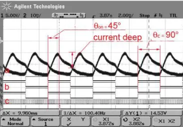
Figs. 5 and 6 display the results of these strategies with the reference rotor and it is observed that
the Single Pulse with Overlapping Phase Current strategy presented a current deep reduction between
two consecutive phase current pulses of 13% in relation to the Single Pulse strategy. While in the
Figs. 7 and 8 are shown the results with the optimized rotor, where the current deep reduction is 14%.
In spite of the representative results obtained with this method, there are difficulties to find the best
value of the angles through the try-and-error process. Moreover, to implement that strategy it is
necessary a more accurate positioning sensor and a more elaborated converter with flexibility to
impose the commutation strategies with overlapping phase current. The Power Electronic Converter
was assembled as in the configuration (B) and the DSP command signals were implemented in
negative logic due to the utilization of the IRAMS10UP60B power module.
Fig. 5. Single Pulse strategy waveforms (θon = 45°, θc = 90° and reference rotor): a) Phase currents (A) and (B), b) DSP
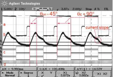
Fig. 6. Single Pulse with Overlapping Phase Currents strategy waveforms (θon = 45°, θc = 100° and reference rotor): a)
Phase currents (A) and (B), b) DSP Command signals and c) Optical sensors signals
Fig. 7. Single Pulse strategy waveforms (θon = 45°, θc = 90° and optimized rotor): a) Phase currents (A) and (B), b) DSP
Command signals and c) Optical sensors signals
Fig. 8. Single Pulse with Overlapping Phase Current strategy waveforms (θon = 45°, θc = 100° and optimized rotor): a)
Phase currents (A) and (B), b) DSP Command signals and c) Optical sensors signals
B. Three Level Control
This strategy is based on a work initiated by Hedlund apud Rasmussen [10] and proposes the SRM
in Fig. 9. The commutation states are defined as a different voltage level which must be applied to a
distinct angular interval. The main characteristic of this commutation strategy is that it is not
switched, so it can be applied in high speed and at nominal condition of operation. According to
Hedlund, this strategy reduces the vibration and the acoustic noise effects since it reduces the high
current transient that occurs during the application of the reverse voltage in the SRM phases which
induces high magnitude in the first vibration mode. In Fig. 9 it is illustrated the phase current, the
voltage and the ideal inductance waveforms with the SRM operating in the Three Level Control
strategy. Furthermore, in the same figure it is shown the details of the three angular intervals (θ1, θ2 e
θ3) and the three voltage levels (+v, zero e -v) necessaries to the application. Again, for obtaining the
best angular intervals (θ1, θ2 e θ3), trial and error tests were performed and the following angular
intervals were determined: θon = 45°, θ1 = 90°, θ2 = 20° and θ3 = 70°. Like the last case, it was
considered relative values and the Single Pulse strategy was used as reference.
The vibration levels with both strategies and both rotors are presented in Figs. 14 and 15 on section
IV. In Figs. 10, 11, 12 and 13 it is shown the phase voltage, the phase current, the DSP Command
signals and the optical sensor signals waveforms of the SRM operating in Single Pulse strategy and in
the Three Level Control strategy. Figs. 10 and 11 show the results of these strategies obtained with
the reference rotor, while in the Figs. 12 and 13 are shown the results with the optimized one.
Comparing the Figs. 10, 11, 12 and 13 it can be noted that, for both rotor types, the Three Level
Control strategy presents a minor current slope. The current slope occurs during the application of
reverse voltage in the SRM phases and its reduction results in smaller vibration as shown in the
section IV. Despite the good results there are disadvantages related to the hard and stressful work to
find the angular intervals. Moreover, this strategy needs a more accurate rotor position sensor. As
before, the DSP command signals were implemented in negative logic, thus the DSP output signals
are active in zero logic level.
Fig. 10. Single Pulse strategy waveforms (θon = 45° e θc = 90° and reference rotor): a) Phase voltage, b) Phase current, c)
DSP Command signals and d) Optical sensor signals
Fig. 11. Three Level Control strategy waveforms (θon = 45°, θ1 = 90°, θ2 = 20°, θ3 = 70° and reference rotor): a) Phase
voltage, b) Phase current (channel 2), c) DSP Command signals and d) Optical sensor signals
Fig. 12. Single Pulse strategy waveforms (θon = 45° e θc = 90° and optimized rotor): a) Phase voltage, b) Phase current, c)
Fig. 13. Three Level Control strategy waveforms (θon = 45°, θ1 = 90°, θ2 = 20°, θ3 = 70° and optimized rotor): a) Phase voltage, b) Phase current, c) DSP Command signals and d) Optical sensor signals
IV. RESULTS
To accomplish the experimental tests a piezoelectric accelerometer sensor was connected in the
SRM stator outer case. The accelerometer sensor signal was fed into the amplifier and the
conditioning module (Charge Amplifier). The output voltage signal from the Charge Amplifier was
fed into the Dynamic Signal Analyzer to carry out the signal treatment in the frequency domain. The
vibration experimental results were obtained in frequency domain for the reference rotor and for the
optimized one. In the tests it was not considered absolute values of vibration, but relative ones.
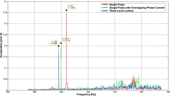
The Single Pulse strategy was used as reference in the comparisons with the other two proposed
strategies. It was noticed that at the nominal rotor speed, 100 Hz or 6000 rpm, the main component of
the torque ripple frequency was 400 Hz (four times the rotor frequency) due to the number of stator
poles. Considering the experimental tests carried out with the reference rotor, in Fig. 14 it was
observed the application of two different commutation strategies to minimize the torque ripple and
vibration at nominal conditions: Single Pulse with Overlapping Phase Current and Three Level
Control. Comparing these strategies one can conclude that the Single Pulse with Overlapping Phase
Current strategy presents a vibration reduction of 23% at torque ripple frequency, while the Three
Fig. 14. Vibration Analysis with reference rotor (range: 380 – 800 Hz)
In Fig. 15 the vibration results were compared for two different strategies applied to the optimized
rotor at nominal conditions (torque and speed). The Single Pulse with Overlapping Phase Current
strategy presents a vibration reduction of 41%, while the Three Level Control strategy presents a
vibration reduction of 45%.
Fig. 15. Vibration Analysis with optimized rotor (range: 380 - 480 Hz)
Comparing the Figs. 14 and 15 one can observe a drastic attenuation in the vibration magnitude due
the proposed control strategies contributed for a further reduction.
In Fig. 16 it is compared the vibration results for the Single Pulse with Overlapping Phase Current
and the Three Level Control and it can be seen that the last one provided a reduction in the vibration
magnitude for all frequency spectrum.
Fig. 16. Vibration Analysis with optimized rotor (range: 0 – 800 Hz)
Fig. 17 depicts the comparison between the Single Pulse and the Three Level Control. Like the last
case, it was noticed a reduction of vibration in all frequency spectrum. Comparing the Figs. 16 and 17
it was observed that the Three Level Control strategy presents the best results in the vibration
Fig. 17. Vibration Analysis with optimized (range: 0 – 800 Hz)
In order to verify the influence of the control strategies in the efficiency of the motor drive, it was
implemented some tests with the SRM driven by the three strategies (Single Pulse, Single Pulse with
Overlapping Phase Current and Three Level Control).
The Single Pulse Control Strategy setup also was used as a reference in the efficiency tests. The
Table I resume the efficiency results obtained in these tests. In spite of the representative results of
vibration obtained (45% of reduction), the optimized rotor associated with the Three Level Control
Strategy setup presented a minor efficiency (65.95%). This value is approximately 3% lower than that
obtained with the Single Pulse Control Strategy setup (69.33%).
Similarly, the optimized rotor associated with the Single Pulse with Overlapping Phase Current
Control Strategy setup (vibration reduction of 41%) presented almost the same efficiency (66.12%).
Thus, the efficiency results revels that the control strategies used in the motor drive cause low
losses of efficiency (3%) when compared to the vibration reduction levels reached.
In Table I, the power input (Pin) is defined as the power provided by D.C. Power Supply connected
to the power electronic converter input; and the (Pout) is defined as the mechanical power available in
TABLE I. MOTOR DRIVE EFFICIENCY TEST
Test Setup Pin [W] Pout [W] η = (Pin/ Po)*100 [%%%%]
Reference rotor with Single Pulse 254.8.0 175.92 69.04
Optimized rotor with Single Pulse 253.65 175.92 69.33
Reference rotor with Single Pulse with Overlapping Current 262.20 175.92 67.10 Optimized rotor with Single Pulse with Overlapping Current 266.07 175.92 66.12 Optimized rotor with Three Level Control 261.32 175.92 67.32 Reference rotor with Three Level Control 266.76 175.92 65.95
V. CONCLUSIONS
The SRMs present major vibration, torque ripple and acoustic noise characteristics. Moreover,
when operating in high speed and nominal conditions, they have a limited processing time to execute
their control instructions and a high back-emf that disable the implementation of switched control
techniques in the motor phases. Thus, this work proposed two control and commutation strategies that
produce less vibration and torque ripple in the SRM: the Three Level Control and the Single Pulse
with Overlapping Phase Current both implemented in open loop control mode.
In order to implement these commutation strategies it was assembled a dedicated digital setup
composed of a development kit (eZdsp LF2407A), a serial control interface developed on a LabView
application and a simple Power Electronic Converter (IRAMS10UP60B).
Comparing the experimental results, it was observed that the vibration and torque ripple problem
must be analyzed under two aspects: mechanical and electronic. The mechanical improvements,
related to the geometrical optimization of the rotor poles, resulted in a reduction of 75% in the
vibration. Additionally, the electronic implementation, the Three Level Control, provided more 45%
vibration reduction in the final results.
To verify the influence of the control strategies on the efficiency, several tests were carried out in
the nominal condition. The results indicate that the control strategies proposed in this work caused
minor reductions in the efficiency of the motor drive when compared to the reached vibration
reduction levels.
ACKNOWLEDGMENT
The authors acknowledge J. Sanches and F. Junqueira for technical support in the vibration tests, L.
Buzo for the figures edition, A. Tosin for helping us with the technical and manuscript review and
finally the support of the CTMSP.
REFERENCES
[1]P. Pillay, W. Cai, “An Investigation into Vibration in the Switched Reluctance Motor”, IEEE Trans. Industry Applic., vol.35, nº 3, pp. 589-596, May/June 1999.
[3]C. G. C. Neves, R. Carlson, N. Sadowski, J. P. A. Bastos, N. S. Soeiro, S. N. Y. Gerges, “Vibrational Behavior of Switched Reluctance Motors by Simulation and Experimental Procedures”, IEEE Trans. Magnetics, vol. 34, nº 5, pp. 3158-3161, Sep. 1998.
[4]R. S. Wallace, D. G. Taylor, “A Balanced Commutator for Switched Reluctance Motors to Reduce Torque Ripple”, IEEE Trans. Power Electron., vol. 7, nº 4, pp. 617-626, Oct. 1992.
[5]I. Husain, “Minimization of Torque Ripple in SRM Drives”, IEEE Trans. Industrial Electron., vol. 49, nº 1, pp. 28-39, Feb. 2002.
[6]S. I. Nabeta, I. E. Chabu, L. Lebensztajn, D. A. P. Correa, W. M. da Silva, et al., “Mitigation of the Torque Ripple of a Switched Reluctance Motor through a Multi-Objective Optimization”, IEEE Trans. Magnetics, v. 44, nº 4, pp. 411-414, Apr. 2008.
[7]Data sheet, International Rectifier, IRAMS10UP60B, Jul. 2005. [8]LabView Software v. 7.0.
[9]Technical Reference, Spectrum Digital, eZdsp LF2407A, Dec. 2000;
[10]P. O. Rasmussen, “Design and Advanced Control of Switched Reluctance Motors“, Ph.D. Thesis, Aalborg University, Denmark, 2002.
[11]I. E. Chabu, S. I. Nabeta, J. R. Cardoso, “Design Aspects Of 4:2 Pole-2 Phase Switched Reluctance Motors”, Proceedings of the IEEE-IEMDC’99, v. 1, p. 63-65, 1999.
[12]L. Lebensztajn, et al., “Kriging: a useful tool to electromagnetic devices optimization”, IEEE Trans. Magnetics, vol. 40, nº 2, pp. 1196-1199, Mar. 2004.