ISSN 0104-6632 Printed in Brazil
www.abeq.org.br/bjche
Vol. 28, No. 01, pp. 81 - 88, January - March, 2011
Brazilian Journal
of Chemical
Engineering
DILUTE-PHASE PNEUMATIC CONVEYING OF
POLYSTYRENE PARTICLES: PRESSURE DROP
CURVE AND PARTICLE DISTRIBUTION OVER
THE PIPE CROSS-SECTION
S. M. Santos
1, E. B. Tambourgi
1, F. A. N. Fernandes
2, D. Moraes Júnior
3*and M. S. Moraes
31Faculdade de Engenharia Química, Universidade Estadual de Campinas, Cidade Universitária
Zeferino Vaz, C. P. 6066, 13083-970 Campinas - SP, Brazil.
2Universidade Federal do Ceará, Departamento de Engenharia Química,
Phone: + (55) (85) 33669611, Fax: + (55) (85) 3366-9610, Campus do Pici, Bloco 709, 60455-760, Fortaleza - CE, Brazil.
E-mail: [email protected]
3Universidade Santa Cecília, Departamento de Engenharia Química,
Fax: + (55) (13) 3202-7132, R. Oswaldo Cruz 266, 11045-907 Santos - SP, Brazil, E-mail: [email protected]; [email protected]
(Submitted: May 14, 2010 ; Revised: August 8, 2010 ; Accepted: August 27, 2010)
Abstract - During the pneumatic conveying of plastic pellets, it has been observed that materials with similar physical characteristics may develop a substantial difference in pressure drop. In this work, the pressure drop in a particle-laden 2.7 meter long horizontal channel with circular cross-section is presented from an experimental perspective. Experiments are carried out for cylindrical polystyrene beads with an average diameter of 3.2 mm and mass loadings of 0.06 to 0.11 (kg particles/kg gas). The air mass flow rate was studied in the range from 0.085 kg/s to 0.170 kg/s. The pressure drop curve is shown as a function of air velocity and particle load. Response surface methodology showed high statistical significance for air velocity, particle load and their cross-relation.
Keywords: Pneumatic conveying; Particulate solids; Polystyrene; Particle distribution; Pressure loss.
INTRODUCTION
Pneumatic conveying of solid particles in channel or pipe flows is of great technical importance and is characterized by particle phase segregation due to gravity and particle inertia. Due to the presence of the confinement in these systems, the collisions of the solid particles with the walls play an essential role in the particle transport process. The wall collision frequency is directly responsible for the additional pressure drop due to the solids as a result of the momentum and energy loss involved in the deformation process (Adam, 1960; Vásquez et al., 2008).
A considerable number of industrial and chemical processes use pneumatic conveying systems to transport solids particles such as cereals, minerals,
chemicals and pharmaceuticals. Transport of particles occurs by means of gases flowing either in inclined, vertical or horizontal pipes. In most cases, air is used as carrier, but under certain conditions its use can cause hazards such as risks of explosion, fire and environmental contamination (Marcus et al., 1990; Li and Tomita, 2000).
Brazilian Journal of Chemical Engineering
A number of experiments were performed in the past aiming at a detailed analysis of particulate flows in pipes and channels, which have been reviewed by Sommerfeld (2003). Tsuji and Morikawa (1982, 1984) studied a gas–solid flow in a horizontal and vertical pipe using different types of relatively large polystyrene spheres. Numerical modeling of pneumatic conveying of solid particles in horizontal tubes has been published by several authors (Kuang et al., 2008; Lain et al., 2009; Sommerfeld and Lain, 2009), but experimental work is still needed to determine pressure drop curves.
Solid flow in conveying pipelines is usually carried out by applying two different flow techniques: dense phase and dilute phase. In dense phase, a high concentrations of solids, typically greater than 30% v/v, and velocities varying from 1 to 5 m/s are applied. The dense-phase regime has high acquisition, operating and maintenance costs, because it requires high gas pressures (pressures above 20 mbar/m). Dilute-phase conveying operates at solid concentrations lower than 1% v/v and velocities above 20 m/s. The dilute-phase regime has lower cost, but it provokes irregular pipe wear at low transport velocities, mainly in the lower parts of horizontal pipes.
The performance of a pneumatic conveying system in the dilute phase is highly affected by the pressure drop, which in turn depends on several parameters such as material properties, pipe designs and airflow.
The objective of this study was to obtain the pressure drop curve for cylindrical polystyrene
particles and to analyze the effects of air velocity and solid load on the pressure drop. Response surface methodology was used to analyze the influence of air velocity and solid load on the pressure drop response.
MATERIALS AND METHODS
Experimental Apparatus
The total length of the cylindrical channel of the experimental apparatus was 4.2 m. The first part of the channel was 1.5 m long and served to get a fully developed gas flow before the feeding point of the polymer particles. The initial part of the cylindrical channel has a flow conditioner, placed 0.9 m after the blower, which serves to homogenize the velocity profile in the pipe flow. The flow conditioner is also intended to accelerate the formation of a fully developed turbulent velocity profile, which is obtained at approximately 25 diameters downstream from the conditioner (Xiong et al., 2005).
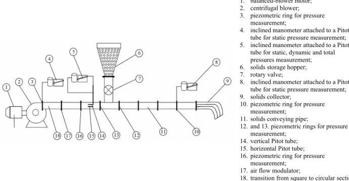
The main component of the experimental apparatus consisted of a cylindrical channel, placed after the feeding point of the particles, with 2.7 m in length and 117 mm in internal diameter. This configuration allowed establishment of a two-dimensional flow condition, where gravity breaks down the cylindrical symmetry in the two-phase flow due to particle settling (Figures 1 and 2).
1. balanced-blower motor;
2. centrifugal blower;
3. piezometric ring for pressure
measurement;
4. inclined manometer attached to a Pitot
tube for static pressure measurement;
5. inclined manometer attached to a Pitot
tube for static, dynamic and total pressures measurement;
6. solids storage hopper;
7. rotary valve;
8. inclined manometer attached to a Pitot
tube for static pressure measurement;
9. solids collector;
10.piezometric ring for pressure
measurement;
11.solids conveying pipe;
12.and 13. piezometric rings for pressure
measurement; 14.vertical Pitot tube; 15.horizontal Pitot tube;
16.piezometric ring for pressure
measurement;
17.air flow modulator;
18.transition from square to circular section.
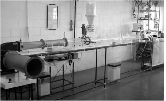
Figure 2: Pilot pneumatic conveying system: installation view.
Air was introduced by a centrifugal blower (Ventisilva, Brazil) with 100 mm diameter semi-open blades, a 203 mm diameter suction line, and a 102 mm square discharge section attached to a 1 Hp variable rotation motor, to which two extra bearings were added (balanced-blower motor) to assess the mechanical power.
The total pressure and the static pressure were measured by means of Pitot tubes. The tubes consisted of two “L” shaped coaxial tubes 190 mm in length. The inner tube had an internal diameter of 3 mm and the external tube had an internal diameter of 8 mm, and was built following ASME code. The total pressure was obtained by the central tube of the Pitot tube, while the static pressure was obtained by small orifices placed in the wall of the external tube of the Pitot tube. The dynamic pressure was determined as the difference between the total and static pressures. The Pitot tubes were place 0.13 m after the first piezometric ring and 0.53 m after the flow conditioner.
The first, second, third and fourth piezometric rings were placed, respectively, at 0.40 m, 0.60 m, 1.20 m and 3.00 m after the flow conditioner.
The solids were fed from the feeder vessel to the conveying pipe by means of a rotary valve with six radial blades, measuring 92 mm by 42 mm and 76.2 mm in diameter. The solids were discharged into a collector module placed at the end of the horizontal pneumatic conveyor. The particle-distribution analysis module was comprised of nine square section aluminum pipes, to which nylon bags were attached to collect the solid particles (Figure 3). The loading, μ (solids mass flow/air mass flow), was controlled by the interaction of the airflow valve and the rotary valve.
Figure 3: Schematics of the particle collector.
Material
Polystyrene particles (PS) were used in the tests and were provided by BASF. The properties of the polystyrene particles are presented in Table 1.
Table 1: Properties of the polystyrene particles.
Shape cylindrical
Particle diameter (mm) 3.2
Density (kg/m3) 1.050
Experiments
Brazilian Journal of Chemical Engineering
under these conditions were respectively 0.5 kg particle/kg air and 7.8 kg particle/kg air.
The distribution of polystyrene in the piping was determined based on the solid mass settled in the nine-pipe collection module, placed at the end of the conveying line; the pipes were numbered as shown in Figure 3. The mass collected in each bag was used to calculate the mass fraction per unit area, which then allowed calculation of the dispersion of polystyrene in the cross-section of the pipe for all air velocities and solids mass flow rates.
The particle density was calculated for the nine collectors and the points were also treated using surface response methodology. The software Statistica v7.0 was used to generate the particle distribution profile based on the interpolation of the data using the distance-weighted least square method. This method was applied because it gave better fitting of the data for non-symmetrical profiles.
RESULTS AND DISCUSSION
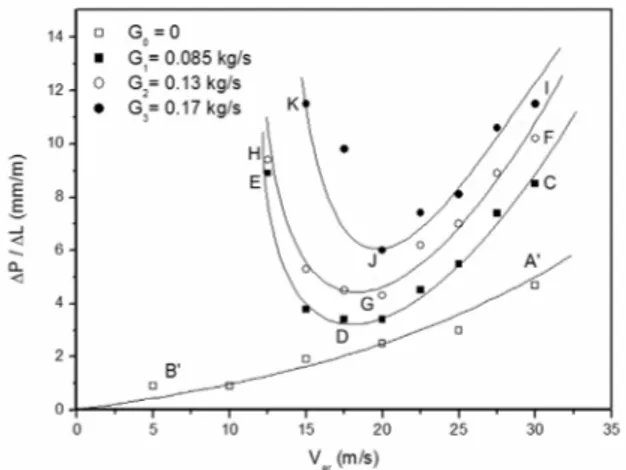
The pressure drop measurements in the horizontal and vertical direction were normalized as ΔP/L, where L is the distance between the pressure taps. Figure 4 shows the pressure drop for the polystyrene particles in the horizontal direction as a function of loading and air velocities. The A’B’ section in Figure 4 represents the pressure drop caused by the air flow (solid-free flow rate G0 = 0) throughout the horizontal transport line. The pressure drop increased as the velocity increased because of internal friction, air-to-wall friction and flow perturbations.
Figure 4: Pressure drop per unit length for polystyrene cylindrical particles as a function of air velocity and the solids flow rate.
The CDE section in Figure 4 represents the
pressure drop profile at a solid flow rate of 0.085 kg/s (G1). High air velocity (25 m/s) resulted in a relatively high pressure drop. As the air velocity decreases and the solids mass flow rate is kept constant, the pressure drop reaches a minimum point and then increases because of settling of the solids in the lower section of the horizontal pipes. The same behavior was observed for all solid flow rates (G2 = 0.13 kg/s and G3 = 0.17 kg/s).
Response surface methodology was used to analyze the effects of the operating conditions on the pressure drop of polystyrene particles. Table 2 presents the analysis of the perturbation of the factors on pressure drop. The results showed that the solid loading and the quadratic effect of air velocity (v2) were statistically significant at the 99% level of confidence (p < 0.01). Both operating conditions had a positive effect on pressure drop, meaning that an increase in solid loading or in air velocity tends to increase the pressure drop for polystyrene beads. The total pressure gradient increased with increasing solid mass flow rate at constant air velocity. The pressure drop increase at a high solids flow rates can be attributed to higher cross-sectional solid concentration in the pipe, creating an extra resistance to air flow through the system.
Table 2: Analysis of perturbation of the factors on the pressure drop of polystyrene particles in horizontal pipes.
Factor Effect Standard
Error p
Mean 4.589 0.489 0.0000
G * 4.000 0.590 0.0000
G2 1.691 0.992 0.1063
v 0.779 0.753 0.3154
v2 * 9.697 1.323 0.0000
G×v -1.610 0.956 0.1105
* significant effects at a confidence level of 95%; G is the solid loading; v is the air velocity.
The positive significance at the 99% level of confidence of the quadratic term of air velocity indicates that an increase in air velocity will have a much higher influence on pressure drop than the solid loading. The cross-interaction between air velocity and solid loading was negative, which means that, under certain operating conditions, a minimum in the pressure drop can be found, as observed in Figure 4.
The pressure drop for air flow in the pipe (G = 0) can be expressed by Equation (1):
2
P
0.90 0.0043 v 0.0037 v L
Δ = − ⋅ + ⋅
The pressure drop for two-phase flow in the horizontal pipe (G = 0.085 to G = 0.17) can be expressed by Equation (2) (in mm/m) or Equation (3) (in Pa/m):
2
2
P
27.98 26.30 G 468.08 G L
2.37 v 0.063 v 2.16 G v
Δ = − ⋅ + ⋅ −
Δ
⋅ + ⋅ − ⋅ ⋅
(2)
where ΔP/ΔL is the pressure drop (mm/m), G is the solid flow rate (kg/s) and v is the air flow rate (m/s).
2
2
P
3730 357 G 62408 G L
16 v 8.4 v 288 G v
Δ = − ⋅ + ⋅ −
Δ
⋅ + ⋅ − ⋅ ⋅
(3)
where ΔP/ΔL is the pressure drop (Pa/m), G is the solid flow rate (kg/s) and v is the air flow rate (m/s).
To become universally valid for any pipe diameter, Equation (3) can be redefined as shown in Equation (4):
(
)
0.5 20 air 1 2.5 2 5
air
0.5
2
air air
3 0.5 4 5 3
P g 1
a g a G a G
L D D
g 1
a v a v a G v
D
D D
⎛ ⎞ ⎛ ⎞
Δ = ρ + + +
⎜ ⎟ ⎜ ⎟
⎜ ⎟ ⎜ ⎟
Δ ⎝ ⎠ ⎝ρ ⎠
⎛ρ ⎞ + ⎛ρ ⎞ + ⎛ ⎞ ⋅
⎜ ⎟ ⎜ ⎟ ⎜ ⎟
⎜ ⎟ ⎝ ⎠ ⎝ ⎠
⎝ ⎠
(4)
(
air)
0.52.50.5 2 air 5 0.5 air 2 air 3 P g
322.6 g 0.534 G
L D
1 g
1.615 G 29.261 v
D D
1
0.833 v 0.461 G v
D D
⎛ ⎞
Δ = ρ + +
⎜ ⎟
⎜ ⎟
Δ ⎝ ⎠
⎛ ⎞ + ⎛ρ ⎞ +
⎜ ⎟ ⎜ ⎟
⎜ρ ⎟ ⎜ ⎟
⎝ ⎠ ⎝ ⎠ ρ ⎛ ⎞ + ⎛ ⎞ ⋅ ⎜ ⎟ ⎜ ⎟ ⎝ ⎠ ⎝ ⎠ (5)
where ΔP/ΔL is the pressure drop (Pa/m), D is the pipe diameter (m), G is the solid flow rate (kg/s), g is the acceleration due to gravity (m/s2), v is the air flow rate (m/s), and ρa is the air density (kg/m3).
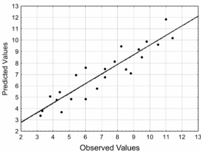
The regression model for the pressure drop of polystyrene particles in horizontal pipes and for the pressure drop of air flow in horizontal pipes was validated by means of the F-test (Table 3). The results of the test showed that the calculated value was more than 4 times higher than the listed F-value (for 95% confidence level), indicating that the
regression model is valid and can be used for the prediction of the pressure drop of polystyrene particles in horizontal pipes. A plot of the predicted values and the observed values is shown in Figure 5.
Solids are totally suspended in the air stream when the air velocity high. As the air velocity is reduced, the solids move more slowly and tend to settle in the lower section of the pipeline. When the air velocity is insufficient to keep all particles suspended, the particles start settling at the bottom of the pipe until total choking of the cross-section occurs (Rhodes, 2000). At this point, the solids are transported in the dense phase along the bottom of the pipe. This point marks the boundary between the dilute and dense phases of pneumatic conveying in a horizontal line.
Vásquez et al. (2008) have studied pressure drop curves for 4 mm polyethylene particles (hard and soft particles) for velocities between 15 and 30 m/s and solid load/air mass flows between 0.5 and 2.5. The results obtained by Vásquez et al. (2008) are similar to the pressure drop for polystyrene particles obtained herein. Vásquez et al. (2008) claimed that the increased pressure drop is in part due to the multiple times that the particles must be reaccelerated during their transit through the conveying system. Additionally, intense bouncing increases the difference in axial velocity between the solids and the air, increasing the drag force on the particles.
Tomita and Asou (2009) studied the transport of polyethylene particles in a horizontal pipe at very low velocity (< 8 m/s). They observed a high pressure loss, like the trend reported in this study for low air velocities, which could also be fit by an equation similar to Equation (3). The same typical result was observed by Pahk and Klinzing (2008) for polystyrene particles, but at high air velocity and for a slightly bigger particle diameter (3.9 mm).
Brazilian Journal of Chemical Engineering
Table 3: ANOVA of the regression model for pressure drop of polystyrene particles in horizontal pipes and for air flow in horizontal pipes.
SS DF MS F-value
ANOVA for two-phase flow
Regression 120.90 5 24.18 19.34
Erro 21.19 17 1.25
Total SS 142.09 22
ANOVA for air flow
Regression 7.236 2 3.618 28.78
Error 0.377 3 0.128
Total SS 7.613 5
Listed F-value (5, 22) = 2.66; Listed F-value (2, 5) = 5.78
Figure 5: Predicted values against observed values for the pressure drop correlation.
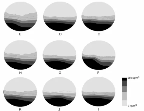
Figure 6 shows that a non-uniform particle distribution in the cross-section of the tube may occur, even far from the minimum pressure drop points. At the highest air velocity (23 m/s) and the lowest solids flow rate (0.085 kg/s), the solids were in large part transported near the bottom of the pipe, with 83% of the polystyrene particles present in the collectors 7, 8 and 9 (Figure 3). The transport of polystyrene particles in the pipe was not uniformly distributed under any operating condition. The best distribution was found when the pneumatic transport was operated at high air velocity and low polyethylene flow rates. Even then, 68% of the particles were moving along the bottom of the pipe and only 16% of the particles were collected in the upper level of the pipe.
The particle distribution in the cross-section of the tube obtained in this work was similar to the particle density profiles for horizontal pipe flow obtained by advanced techniques such as extended Laser Doppler Anemometry (LDA). Lu et al. (2009)
studied the transport of glass beads by using the extended LDA technique and reported particle distributions similar to the ones obtained herein.
The Stokes number for all conditions applied herein was higher than 1, indicating that the particle motion is independent of the carrier gas flow, as it was not able to respond to its changes. The lowest Stokes number calculated for the two-phase flow was 1.53, obtained at an air flow velocity of 5 m/s, which is near the theoretical boundary between a rapid and a slow response time of the particles to a change in air velocity. The highest Stokes number calculated for the two-phase flow was 10.7, obtained at an air flow velocity of 35 m/s.
Figure 6: Particle density inside the pipe for polystyrene cylindrical particles. C. G = 0.085 kg/s, v = 30 m/s; D. G = 0. 085 kg/s, v = 13 m/s; E. G = 0. 085 kg/s, v = 12 m/s; F. G = 0.11 kg/s, v = 30 m/s; G. G = 0. 11 kg/s, v = 20 m/s; H. G = 0. 11 kg/s, v = 12 m/s; I. G = 0.17 kg/s, v = 30 m/s; J. G = 0. 17 kg/s, v = 20 m/s; K. G = 0. 17 kg/s, v = 15 m/s.
CONCLUSIONS
Polystyrene presented a non-uniform particle distribution in horizontal pneumatic transport in pipes. Transport of cylindrical polystyrene particles is mainly in the lower sections of the pipe, even at low solid loads and high air velocities. The best distribution was found when the system was operated at high air velocity and low polystyrene loads. The results show the importance of studying the dispersion of particles and the characteristic curve of the system.
ACKNOWLEDGMENTS
The authors thank CNPq for the award of a scholarship, and the Universidade Santa Cecília (UNISANTA) for building the pilot pneumatic transport facility.
REFERENCES
Adam, O., Untersuchungen über die Vorgänge in festoffbeladenen Gasströmungen. Forschungsberichte
des Landes Nordrhein-Westfalen. Westdeutscher Verlag, Köln (1960).
Hirota, M., Sogo, Y., Marutani, T. and Suzuki, M., Effect of Mechanical Properties of Powder on Pneumatic Conveying in Inclined Pipe. Powder Tech., 122, 150 (2002).
Klinzing, G. E., Marcus, R. D., Rizk, F. and Leung, L. S., Pneumatic conveying of solids: a theoretical and practical approach. Chapman & Hall, London (1997).
Kuang, S. B., Chu, K. W., Yu, A. B., Zou, Z. S. and Feng, Y. Q., Computational investigation of horizontal slug flow in pneumatic conveying. Ind. Eng. Chem. Res., 47, 470 (2008).
Lain, S., Sommerfeld, M. and Quintero, B. Numerical simulation of secondary flow in pneumatic conveying of solid particles in a horizontal circular pipe. Braz. J. Chem. Eng., 26, 583 (2009).
Li, H. and Tomita, Y. Particle velocity and concentration characteristics in a horizontal dilute swirling flow pneumatic conveying. Powder Tech., 107, 144(2000).
Brazilian Journal of Chemical Engineering
technique. Fuel, 88, 2520 (2009).
Marcus, R. D., Leung, L. S. and Klinzing, G. E., Pneumatic Conveying of Solids: A Theoretical and Practical Approach. Chapman and Hall, New York (1990).
Molerus, O., Overview: Pneumatic Transport of Solids. Powder Tech., 88, 309(1996).
Pahk, J. B. and Klinzing, G. E., Comparison of flow characteristics for dilute phase pneumatic conveying for two different plastic pellets. J. Chin. Inst. Chem. Eng., 39, 148 (2008).
Rhodes, M., Introduction to particle technology. John Wiley & Sons, New York (2000).
Sommerfeld, M. Analysis of collisions effects for turbulent gas-particle flow in a horizontal channel: Part I. Particle transport. Int. J. Multiph. Flow, 29, 675(2003).
Sommerfeld, M. and Lain, S. From elementary processes to the numerical prediction of industrial particle-laden flows. Multiph. Sci. Tech., 21, 123
(2009).
Tomita, Y. and Asou, H., Low-velocity pneumatic conveying of coarse particles in a horizontal pipe. Powder Tech., 196, 14 (2009).
Tsuji, Y. and Morikawa, Y. LDV measurements of an air–solid two-phase flow in a horizontal pipe. J. Fluid Mech., 120, 385(1982).
Tsuji, Y. and Morikawa, Y. LDV measurements of an air–solid two-phase flow in a vertical pipe. J. Fluid Mech., 139, 417(1984).
Vásquez, N., Jacob, K., Cocco, R., Dhodapkar, S. and Klinzing, G. E., Visual analysis of particle bouncing and its effect on pressure drop in dilute phase pneumatic conveying. Powder Tech., 179, 170 (2008).